Table of Contents
Advertisement
Quick Links
WARNING:
If the information in these instructions is not followed exactly, a fire or explosion may result
causing property damage, personal injury or loss of life.
-
Do not store or use gasoline or other flammable vapors and liquids in the vicinity of this or any other
appliance.
WHAT TO DO IF YOU SMELL GAS
• Do not try to light any appliance.
• Do not touch any electrical switch; do not use any phone in your building.
• Immediately call gas supplier from a neighbor's phone. Follow the gas supplier's instructions.
• If you cannot reach your gas supplier, call the fire department.
-
Installation and service must be performed by a qualified installer, service agency or the gas supplier.
This appliance may be installed in an
aftermarket permanently located,
manufactured home (USA only) or mobile
home, where not prohibited by local codes.
This appliance is only for use with the
type(s) of gas indicated on the rating
plate. A conversion kit is supplied with
the appliance.
· Cypress
INSTALLER:
Leave this manual with the appliance.
CONSUMER:
Retain this manual for future reference.
© Copyright 2013, T.I.
Owner's Manual
$10.00
100-01311
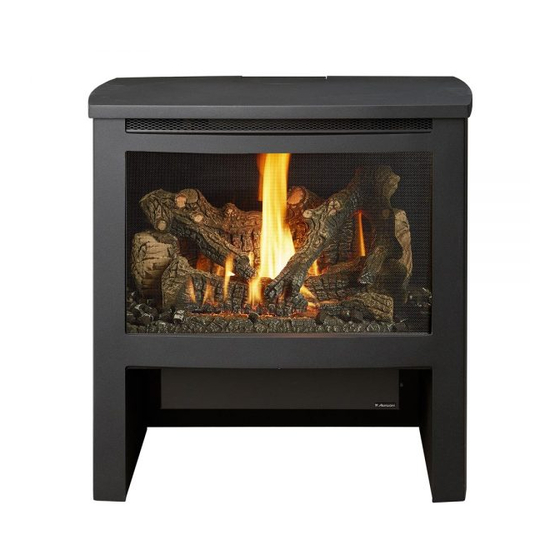
• Direct Vent Freestanding Stove
• Natural Gas or Propane
• Vent Horizontally or Vertically
• Standard Residential
• Mobile Home Approved
Tested and Listed by
ANSI Z21.88 CSA 2.33
2 ·
www.travisproducts.com
4800 Harbour Pointe Blvd. SW
4121130
Mukilteo, WA 98275
Advertisement
Table of Contents

Related Manuals for Avalon Cypress GS2


Summary of Contents for Avalon Cypress GS2
- Page 1 • Direct Vent Freestanding Stove • Natural Gas or Propane • Vent Horizontally or Vertically • Standard Residential • Mobile Home Approved Tested and Listed by ANSI Z21.88 CSA 2.33 WARNING: If the information in these instructions is not followed exactly, a fire or explosion may result causing property damage, personal injury or loss of life.
-
Page 2: Introduction
Introduction Introduction We welcome you as a new owner of a Cypress GS2 stove. In purchasing a Cypress you have joined the growing ranks of concerned individuals whose selection of an energy system reflects both a concern for the environment and aesthetics. The Cypress is one of the finest home heaters the world over. -
Page 3: Table Of Contents
Wiring the Blower to the GSR2 IFC (Bypassing the Top Vent Configuration with Vertical Rheostat) ..............52 Termination ............. 21 Index ..............58 Top Vent Configuration with Horizontal Termination ............. 22 © Travis Industries 4121130 100-01311... -
Page 4: If You Smell Gas
© Travis Industries 4121130 100-01311... - Page 5 “Additional Items Required” instructions in this manual. on page 7). • Plug the heater into a 120V • Travis Industries, Inc. grounded electrical outlet. grants no warranty, Do not remove the implied or stated, for the grounding plug. installation or •...
-
Page 6: Features
This heater is shipped in natural gas (NG) configuration but may be converted to propane (LP) using the included LP conversion kit. The sticker on top of the gas control valve will verify the correct fuel. © Travis Industries 4121130... -
Page 7: Packing List
½” FPT to 3/8” Flare Fitting • Approved Travis Media (Logs 94500561, Driftwood • Rear Vent Cover 94500562, or Stones 94700733) • Driftwood/Stone Conversion Parts Installation Overview "Clearances" See "Vent Requirements" See "Gas Line Installation" See "Floor Protection Requirements" © Travis Industries 4121130 100-01311... -
Page 8: Stove Clearances
45° Rear Vent (Straight) Installations 10" Min. 254mm 8-1/4" Min. 210mm Rear vent installations may not use an elbow with a horizontal termination. We recommend using a top vent configuration if placed in a corner © Travis Industries 4121130 100-01311... -
Page 9: Top To Rear Vent Modification
(for qualified installers only) Top to Rear Vent Modification NOTE: The rear vent parts are included in the Minimum Vent Kit “D” (sku 96200317). If using the rear vent configuration, make sure to review vent configuration before proceeding. © Travis Industries 4121130 100-01311... -
Page 10: Heater Placement Requirements
The appliance, when installed, must be electrically grounded in accordance with local codes or, in the absence of local codes, with the National Electrical Code, ANSI/NFPA 70, or the Canadian Electrical Code, CSA C22.1. © Travis Industries 4121130 100-01311... -
Page 11: Optional Wall Switch Or Thermostat Installation
To wire the heater in parallel, follow the directions below: To wire the heater in series, follow the directions below: On / Off Switch On / Off Switch Thermostat (or External Switch) Wires Thermostat (or External Switch) Wires © Travis Industries 4121130 100-01311... -
Page 12: Gas Line Installation
Contact the local gas supplier if the regulator is at an improper pressure. Standard Input Pressure 7” W.C. (1.74 Kpa) Natural Gas Propane 13” W.C. (3.23 Kpa) © Travis Industries 4121130 100-01311... -
Page 13: Vent Requirements
Approved Vent – Rear Vent Configuration WITH NO VENT RISE: Must use Travis Industries Minimum Vent Kit D (Part # 96200317) only. WITH VENT RISE: Use Travis Industries Rear Vent Conversion ( Part # 94400998) with 8" (204mm) diameter Simpson Dura-Vent Direct-Vent Pro (or GS)*. -
Page 14: Approved Vent Configurations
(see the illustration below). The screw location indicates restrictor position. In this example, the restrictor is set in position # 3. Tighten the screws to secure the restrictor. (closed) # 5 (open - stock position) # 1 © Travis Industries 4121130 100-01311... -
Page 15: Closing The Diffuser (For Top Vent Configurations Only)
The diffuser is found on the inner flue assembly . DIFFUSER SIDE VIEW Bottom of inner Before (Stock - Position # 1) Inner flue assembly flue assembly After (Position # 2) Replace the Remove the diffuser. diffuser. © Travis Industries 4121130 100-01311... -
Page 16: Exhaust Restrictor Extender (For Rear Vent Configurations Only)
Horizontal When a horizontal elbow (90° or 45°) is on vertical terminations. Elbow used, horizontal length is the sum of the two lengths (H1 + H2). Vent Vertical Elbow Height © Travis Industries 4121130 100-01311... -
Page 17: Rear Vent Configuration With No Rise
Rear Vent Configuration with No Rise • Use the minimum vent kit “D” from Travis Industries (SKU 96200317). This kit contains the following components used to vent the stove through a typical exterior wall: -- Travis Thimble (unique to this stove) -- Wall Cover (Black) -- Pipe Section (3.9”) -
Page 18: Rear Vent Configuration With Horizontal Termination
Installation (for qualified installers only) Rear Vent Configuration with Horizontal Termination • Use the rear vent conversion from Travis Industries (SKU 94400998). • Use 8” Diameter Vent • Horizontal sections require a ¼” (6mm) rise every 12” (305mm) of travel. -
Page 19: Rear Vent Configuration With Vertical Termination
Installation (for qualified installers only) Rear Vent Configuration with Vertical Termination • Use the rear vent conversion from Travis Industries (SKU 94400998). • Use 8” Diameter Vent • Horizontal sections require a ¼” (6mm) rise every 12” (305mm) of travel. -
Page 20: Rear Vent Configuration Vented Into Fireplace With Co-Linear Adapter
• Use the following components: -- Travis Industries Rear Vent Conversion ( Part # 94400998) -- Travis Co-Axial to Co-Linear Adapter (4” Exhaust, 3” Intake) (Part # 96200328) -- Gas Insert Vent Kit “G” 3&4 (Part # 96200331) - or - 3”... -
Page 21: Top Vent Configuration With Vertical Termination
Diffuser Closed 5 feet (1.5m) 5 feet (1.5m) 0 feet 0 feet Horizontal Elbow Horizontal elbows are elbows placed between two horizontal sections of pipe. One 45° or 90° horizontal elbow is allowed for this configuration. © Travis Industries 4121130 100-01311... -
Page 22: Top Vent Configuration With Horizontal Termination
5 feet (1.5m) Min. 2' (0.61m) Rise Required 0 feet 0 feet Horizontal Elbow Horizontal elbows are elbows placed between two horizontal sections of pipe. One 45° or 90° horizontal elbow is allowed for this configuration. © Travis Industries 4121130 100-01311... -
Page 23: Vent Termination Requirements (See Illustration Below)
NOTE: Measure clearances to the nearest edge of the exhaust hood. • Use the vinyl siding standoff when installing on an exterior with vinyl siding. • Vent termination must not be located where it will become plugged by snow or other material © Travis Industries 4121130 100-01311... -
Page 24: Steps For Finalizing The Installation
Battery Holder for Control Panel Lights Install the media (logs, driftwood, or stone set - see page 28). Replace the glass. Start the heater. Leak test all gas joints. © Travis Industries 4121130 100-01311... -
Page 25: Air Shutter Adjustment
The flames should burn off of each burner hole. If the heater does not work correctly, contact your Travis dealer for a remedy. 11. Give this manual to the home owner for future reference and fully explain operation of this heater. © Travis Industries 4121130 100-01311... -
Page 26: Face And Glass Removal
Swing the glass frame into place - you may have to lift it slightly to allow it to fit over the top of the firebox. c) Attach the upper latches (follow the instructions above in reverse). d) Replace the stove top and secure with the two screws. © Travis Industries 4121130 100-01311... - Page 27 Top of Firebox Glass Frame Anchor Note how the washer on the latch fits behind the flange on the glass frame anchor. Once fully inserted, turn the latch until it is upright. © Travis Industries 4121130 100-01311...
-
Page 28: Media Installation (Log, Stone, Or Driftwood)28
The burner must be correctly positioned before installing the media. Make sure the burner is fully seated and the pilot is properly aligned. See page 39 for details on burner removal. For installation instructions, consult the instructions included with the log, stone, or driftwood. © Travis Industries 4121130 100-01311... -
Page 29: Before You Begin
This switch turns the rear burner on and off. Comfort Control AA Battery Holder This holder contains 4 AA batteries that allow the stove to operate during power outages. Main Burner This switch turns the stove burners on and off. © Travis Industries 4121130 100-01311... -
Page 30: Starting The Stove For The First Time
Adjusting the Flame Height This stove has an adjustable flame to tailor the look and heat output to your specific needs. It is adjusted by turning the flame adjust knob. © Travis Industries 4121130 100-01311... -
Page 31: Accent Light
Frequent On / Off Operation – if you are frequently turning the stove on and off, you may wish to leave it in continuous pilot. This allows the burner to turn on more quickly, without pilot ignition delay. © Travis Industries 4121130... -
Page 32: Normal Operating Sounds
This appliance has several areas that reach high temperatures. Dust or other particles on these areas may burn and create a burnt-paper smell. This is normal during startup. You may notice the smell is more acute if the appliance was left idle for a long period. © Travis Industries 4121130 100-01311... -
Page 33: Maintaining Your Stove's Appearance
9v battery (see the illustration below). Velcro is provided to secure the 9v battery. Battery Holder AA Battery Tray Swing the control cover down to access the batteries. Battery Holder for Control Panel Lights © Travis Industries 4121130 100-01311... -
Page 34: Accent Light Replacement
When the bulb is inserted into the socket the two posts will be exposed approximately ¼” (6mm) – this is normal. Do not loosen these screws Micro (1/16") Standard (they hold the wires in place). or Philips Screwdriver 35 Watt 120 Volt T4 Halogen Bulb (G6.35 Base) © Travis Industries 4121130 100-01311... -
Page 35: Yearly Service Procedure
Monitor blower operation. 8. Remove any debris or vegetation near the vent termination. Contact your dealer if any sooting or deterioration is found near the vent termination. Venting system should be examined by a qualified agency. © Travis Industries 4121130 100-01311... -
Page 36: Troubleshooting Table
Fan (Blower) Fuse Replacement Parts List Caution: Use only Travis Industries replacement parts. Do not use substitute materials. Warning: Do not operate appliance with the glass front removed, cracked, or broken. Replacement of the glass should be done by a licensed or qualified service person. -
Page 37: Safety Label
Safety Label Safety Label The safety (listing) label is attached under the stove. A copy is shown below. © Travis Industries 4121130 100-01311... -
Page 38: Conditions & Exclusions
2. Travis Industries has the option of either repairing or replacing the defective component. 3. If your dealer is unable to repair your appliance’s defect, he may process a warranty claim through TRAVIS INDUSTRIES, INC., including the name of the dealership where you purchased the appliance, a copy of your receipt showing the date of the appliance’s purchase, and the serial number on your appliance. -
Page 39: Lp Conversion Instructions
Convert the appliance prior to installing the gas line to ensure proper gas use. Access the firebox. Remove the side ember trays. Grasp the burner with both hands and lift it straight up and out of the firebox. Discard the rear air deflector. © Travis Industries 4121130 100-01311... - Page 40 Rear Burner Orifice Front Burner Orifice Thread Sealant 15/16" 24mm 1/2" Wrench Orifice ID ORIFICE SIZE (ID) Natural Gas LP (Propane) Front Burner Orifice #49 DMS #57 DMS Rear Burner Orifice #43 DMS #53 DMS © Travis Industries 4121130 100-01311...
- Page 41 Optional Equipment (for qualified installers only) Install the LP (propane) manifold cover included in owner’s pack (see illustration below). © Travis Industries 4121130 100-01311...
- Page 42 (b) Remove and discard the Natural Gas (NG) orifice. Place the LP orifice in the pilot assembly then replace the pilot hood, tightening the pilot hood until it is snug (do not over-tighten). Natural Gas Orifice = .020N (3way) .020N .018N (2way) .018N LP (Propane) Orifce = .014LP .014LP 7/16" Wrench © Travis Industries 4121130 100-01311...
- Page 43 10 Restore the appliance to the correct configuration. Make the gas line connection, bleed the gas line (if applicable), start the heater and thoroughly leak-test all gas connections and the gas control valve. © Travis Industries 4121130 100-01311...
-
Page 44: Gs2 Remote Installation
If you need to replace dead batteries, make sure to turn the appliance off before removing the batteries. NOTE: If the batteries go dead, the system will operate normally as long as household power (120v AC) is present. © Travis Industries 4121130 100-01311... -
Page 45: Base Wiring Diagram
Ground 3.15A FUSE Base Pilot Sensor Integrated Flame Fireplace Detect Control Spark (IFC) Appliance Ground Comfort Control Valve IPI/CPI Switch Green White ON / OFF Black Comfort Control AA Battery Main Burner Switch Tray Switch © Travis Industries 4121130 100-01311... -
Page 46: Gs2 Remote Wiring Diagram
2.5 Amp Fuse 2.5 Amp Fuse Appliance Ground 3.15A FUSE Integrated Pilot Sensor Fireplace Flame Control Detect (IFC) Spark System Jumper Appliance Ground IPI/CPI JUMPER WIRE Comfort Control Valve Black (4) AA Batteries Battery Box (Manual On/Off) © Travis Industries 4121130 100-01311... -
Page 47: Installation
2. Remove the control panel and place face-down in front of the heater (keep the screws). 3. Disconnect the comfort control and battery backup wires. 4. Remove and place aside the Comfort Control-Battery Plate with harness (the batteries and assembly may be kept for spare parts). © Travis Industries 4121130 100-01311... - Page 48 5. Remove the rear panel from the heater and set aside. It is held in place with seven screws. Screw Locations 6. Disconnect input power. 7. Pull the base IFC to the rear of the stove to access the wiring (it is held in place with Velcro). © Travis Industries 4121130 100-01311...
- Page 49 9. Remove and place aside the base IFC (it may be kept for spare parts). 10. Remove the on/off switch by prying it out. Disconnect the wires. 11. Push the wires back into the holder to conceal them. © Travis Industries 4121130 100-01311...
- Page 50 Place the stepper motor on the gas control valve (see below) – MAKE SURE IT IS CORRECTLY ORIENTED. Secure using the screws included with the motor – tighten to 25 Lb-inches. Leak-test this area after installation to verify proper installation. Route the stepper motor wire near the IFC location. © Travis Industries 4121130 100-01311...
- Page 51 (see “e”) to “FAN” lead on the fuse harness (pre-connected to the IFC). This circuit bypasses the rheostat and snap disc (these components included with the blower kit are not used and may be kept for replacement part purposes). 3.15 © Travis Industries 4121130 100-01311...
-
Page 52: Order Of Installation
Attach the accent light power input (see “d”) to “LIGHT” lead on the fuse harness (pre-connected to the IFC). This circuit bypasses the rheostat (this component is not used and may be kept for replacement part purposes). Accent Light (s) 3.15 15. Place the GSR2 IFC near the appliance. © Travis Industries 4121130 100-01311... - Page 53 (for qualified installers only) 16. Attach the following: (Black) (White) (Green) Pilot connections Power (3 wires – make sure orientation is correct) Comfort Control connection Make sure silicone tubing is pushed down Main Harness Stepper Motor © Travis Industries 4121130 100-01311...
- Page 54 18. Remove the IPI/CPI switch and place aside (may be kept for spare parts). 19. Connect the accent light wires to the GSR2 IFC. NOTE: If using a blower, connect the power input to the GSR2 IFC. © Travis Industries 4121130 100-01311...
- Page 55 22. Place the IFC in location inside the heater and attach using the supplied velcro tape. 23. Use the two included cable ties to make sure all wiring is secure and does not contact any hot or moving parts. © Travis Industries 4121130 100-01311...
- Page 56 Optional Equipment (for qualified installers only) 24. Re-attach the control panel. 25. Attach the battery box to the control panel using the screws removed in step 2. © Travis Industries 4121130 100-01311...
- Page 57 26. Re-connect the input power. 27. Replace the rear panel and restore the stove to the correct configuration (turn on power and gas). See the instructions included with the remote for synchronizing the remote and the operating instructions. © Travis Industries 4121130 100-01311...
-
Page 58: Index
Turning the Stove On and Off ......30 Listing Details ............. 2 Vent Requirements .......... 13 Location of Controls ......... 29 Vent Termination Requirements ...... 23 LP Conversion Instructions ......39 Yearly Service Procedure ........ 35 Maintaining Your Stove's Appearance ..... 33 © Travis Industries 4121130 100-01311...
Need help?
Do you have a question about the Cypress GS2 and is the answer not in the manual?
Questions and answers