Table of Contents
Advertisement
Featuring the
WARNING:
If the information in these instructions is not followed exactly, a fire or explosion
may result causing property damage, personal injury or loss of life.
-
Do not store or use gasoline or other flammable vapors and liquids in the vicinity of this or
any other appliance.
WHAT TO DO IF YOU SMELL GAS
• Do not try to light any appliance.
• Do not touch any electrical switch; do not use any phone in your building.
• Immediately call gas supplier from a neighbor's phone. Follow the gas supplier's instructions.
• If you cannot reach your gas supplier, call the fire department.
-
Installation and service must be performed by a qualified installer, service agency or the gas
supplier.
This appliance may be installed as an OEM installation in a manufactured (mobile) home and
must be installed in accordance with the manufacturer's instructions and the manufactured
home construction and safety standard, Title 24 CFR, Part 3280 or Standard for Installation in
Mobile Homes, CAN/CSA Z240 MH.
This appliance is only for use with the type(s) of gas indicated on the rating plate. A conversion
kit is supplied with the appliance.
Cedar Manual
Installer:
After installation give this manual to the home-owner and
explain operation of this heater.
Copyright 2007, Travis Industries, Inc.
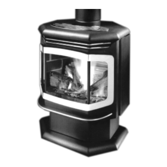
• Direct Vent Freestanding Stove
• Natural Gas or Propane
• Vent Horizontally or Vertically
• Standard Residential
• Mobile Home Approved
Burner
ANSI Z21.88, CSA 2.33 M9 8, CAN/CGA 2.17-M91
$10.00
93508117
Tested and Listed by
Omni-Test Laboratories, Inc.
Beaverton, Oregon
Report # 028–S–38-5
4800 Harbour Pointe Blvd. SW
Mukilteo, WA 98275
Advertisement
Table of Contents

Related Manuals for Avalon Cedar EF


Summary of Contents for Avalon Cedar EF
- Page 1 Installer: After installation give this manual to the home-owner and explain operation of this heater. Copyright 2007, Travis Industries, Inc. • Direct Vent Freestanding Stove • Natural Gas or Propane • Vent Horizontally or Vertically • Standard Residential • Mobile Home Approved Omni-Test Laboratories, Inc.
-
Page 3: Introduction
Introduction We welcome you as a new owner of a Cedar Stove. In purchasing this heater you have joined the growing ranks of concerned individuals whose selection of an energy system reflects both a concern for the environment and aesthetics. The Cedar is one of the finest home heaters the world over. This manual will explain the installation, operation, and maintenance of this gas-burning heater. -
Page 4: Safety Precautions
Safety Precautions • • • • • • Travis Industries IF YOU SMELL GAS: Do not light any appliance Extinguish any open flame Do not touch any electrical switch or plug or unplug anything Open windows and vacate building Call gas supplier from neighbor’s house, if not reached, call fire department This unit must be installed by a qualified installer to prevent the possibility of an explosion. - Page 5 Safety Precautions • Do not place clothing or other flammable items on or near the heater. Because this heater can be controlled by a thermostat there is a possibility of the heater turning on and igniting any items placed on or near it. •...
-
Page 6: Table Of Contents
Heating Specifications ...5 Dimensions...5 Electrical Specifications...5 Fuel...5 Installation Installation Warnings ...6 Packing List...6 Installation Preparation ...6 Stove Clearances ...6 Mobile Home Requirements ...6 Heater Placement Requirements ...7 Floor Protection Requirements...7 Gas Line Installation...7 Gas Inlet Pressure ...7 Vent Requirements...8 Altitude Considerations ...8 Approved Vent Configurations ...9... -
Page 7: Specifications
To measure the net BTU’s, multiply the BTU input by the efficiency percentage. Dimensions: Measure Clearances from the Stove Top Weight: 175 Lbs Fuel: This heater is shipped in natural gas (NG) configuration but may be converted to propane (LP) using the included LP conversion kit. -
Page 8: Installation
Mobile Home Requirements • When the stove is installed in a mobile home, it must be bolted to the floor and the appliance grounded (use the blower with a grounded circuit or other suitable grounding method - current ANSI/NFPA 70 or CSA C22.1). -
Page 9: Heater Placement Requirements
When the stove is installed directly on carpeting, vinyl or other combustible material other than wood flooring or a high pressure laminate wood floor, the stove must be installed on a metal or wood protection panel extending the full width and depth of the heater (Minimum 22-1/2” wide by 17-5/8”... -
Page 10: Vent Requirements
Installation Vent Requirements Always maintain the required 1” clearance (air space) to combustible materials to prevent a fire hazard. Do not fill air spaces with insulation. The gas appliance and vent system must be vented directly to the outside of the building, and never be attached to a chimney serving a separate solid fuel or gas-burning appliance. -
Page 11: Approved Vent Configurations
N O T E : if the vent is already installed, prop up the stove top to adjust the restrictor. Take care to not scratch the vent. Measuring Vent Lengths Travis Industries... -
Page 12: Vertical Term's With 0,2, Or 4 45° Elbows
Installation Vertical Terminations with 0, 2, or 4 45° Offsets Offset Length Hor. Offset None 5" 1' Section 2' Section 1' 9" 3' Section 2' 5" 4' Section 3' 2" • The termination must fall within the shaded area shown in the chart. -
Page 13: Horizontal Terminations With One 90° Elbow
Installation Horizontal Terminations with One 90° Elbow • If using a Snorkel Termination (14” or 36”) add the snorkel height to the vertical height (snorkel terminations are used primarily for basement installations). • The termination must fall within the shaded area shown in the chart. Use the indicated restrictor position. -
Page 14: Horizontal Terminations With Two 90° Elbows
Installation Approved Venting Configurations with a Horizontal Termination and Two Elbows ( • If using a Snorkel Termination (14” or 36”) add the snorkel height to the vertical height (snorkel terminations are used primarily for basement installations). • The termination must fall within the shaded area shown in the chart. Use the indicated restrictor position. -
Page 15: Horizontal Terminations 3 90° Elbows
Installation Approved Venting Configurations with a Horizontal Termination and Three 90° Elbows (all vertical) • If using a Snorkel Termination (14” or 36”) add the snorkel height to the vertical height (snorkel terminations are used primarily for basement installations). • The termination must fall within the shaded area shown in the chart. -
Page 16: Vertical Terminations With Two 90° Elbows
Installation Vertical Terminations with Two 90° Elbows • The termination must fall within the shaded area shown in the chart. Use the indicated restrictor position. 40' (max) 35 feet 30 feet 25 feet 20 feet 15 feet 10' (min) 5 feet 0 feet Travis Industries (for qualified installers only) -
Page 17: Vertical Term's With Three 90° Elbows
Installation Approved Venting Configurations for Vertical Terminations with Three 90° Elbows (Two 90° Vertical and One 45° or 90° Horizontal Elbow) • The termination must fall within the shaded area shown in the chart. Use the indicated restrictor position. 40' (max) 35 feet 30 feet 25 feet... -
Page 18: Termination Requirements
Installation Termination Requirements (see the illustration below) Minimum 9" clearance from any door or window Minimum 12" above any grade, veranda, porch, deck or balcony Minimum 12" from outside corner walls Minimum 12" from inside corner walls Minimum 11" clearance below unventilated soffits or roof surfaces Minimum 18"... -
Page 19: Finalizing The Installation
Installation Finalizing the Installation Turn the gas control valve to “OFF” prior to conducting any service. Install the control box following the instructions below. Place the control box in place and secure with the two screws. NOTE: a tab on the back of the control box inserts into this slot. - Page 20 Installation Let the heater burn for thirty minutes. Adjust the air shutter, if necessary, to achieve the correct looking flame (see the illustration below). • The air shutter adjusts the amount of air that mixes with the gas before it exits the burner holes. It is used to fine-tune the flame for differences in altitude and vent configuration.
-
Page 21: Opening The Door
Installation Opening the Door Open the latch. Strike With the pawl free of the strike, the door may be swung open. Door Frame When securing the door, make sure the pawl fits over the strike before tightening. NOTE: Do not overtighten the pawl by screwing it in. -
Page 22: Log Set And Coal Installation
Installation Log Set and Coal Installation Step 1 Before installing the log set, make sure the burner is seated correctly. Remove the burner following the directions on page 31. Replace the burner making sure it is seated correctly (see page 31). Step 2 Place the rear log on the two platforms at the rear of the... -
Page 23: Operation
Safety Notice Read this entire manual (especially the “Safety Precautions” on pages 2 and 3) before using this stove. damage, bodily injury, or even death. Location of Controls The pilot flame is located below the rear log. Gas Control Valve... -
Page 24: Starting The Pilot Flame
"OFF". However, the pilot will go out if the gas is shut off, the propane tank runs out (or low) or if the stove malfunctions. If the pilot turns off frequently, call your dealer for information. To start the... -
Page 25: Starting The Heater For The First Time
Cleaning Gold Surfaces Fingerprints or other marks left on gold surfaces may become etched in place if they are not wiped clean prior to turning the stove on. With the heater cool, clean gold surfaces with denatured alcohol and a soft cloth. -
Page 26: Adjusting The Blower Speed
Optional Blower - Adjusting the Speed The blower helps transfer heat from the heater into the room. It will not turn on until the heater is up to temperature (approximately 10 minutes after starting). See the illustration below for instructions on adjusting the blower speed. -
Page 27: Maintenance
Fingerprints or other marks left on the optional gold surface may become etched in place if they are not wiped clean prior to turning the stove on. With the heater cool, use denatured alcohol and a soft cloth to clean gold surfaces. Other cleaners may leave a film that may become etched into the gold. -
Page 28: Troubleshooting Steps
Troubleshooting Steps Problem: Pilot Will Not Flame Main Burners Will Not Start Remote Control Does Not Work Thermostat Does Not Work Optional Blower Does Not Operate Flames Are Too Blue Flames Are Too Short (Under 6”) Travis Industries Maintenance Possible Cause: A gas shut off valve is turned off ... -
Page 29: How This Heater Works
How this Heater Works Warning This heater was designed with safety as the primary concern. Many of the components inside this heater are for safety purposes. Therefore, only certified gas service technicians should service this heater. What Turns the Main Burners On and Off This heater uses a millivolt system to control its operation (a millivolt is a very small amount of electricity). -
Page 30: Wiring Diagram
Magnet, w/Sheath 93508117 Manual, Cedar 98900747 On/Off Switch 98900717 Orifice, Burner, .0625 Travis Industries Maintenance On/Off Switch Brown Black White Molex Green Ground (attached to stove) White Black Brown Blue Blue 98900751 93006516 93006515 93006523 93006517 93006509 93006508 93006522 99300656 91001542... -
Page 31: Safety Label
Safety Label The listing label is shown below for your records. It can be found inside the left side panel. Report No. 028-S-38-5 Tested and certified by OMNI-Test Laboratories, Inc. to the combustion performance and construction requirements of ANSI Z21.88b-1999, and applicable sections of UL 307b. -
Page 32: Warranty
Limited 7 Year Warranty To register your TRAVIS INDUSTRIES, INC. 7 Year Warranty, complete the enclosed Warranty card and mail it within ten (10) days of the appliance purchase date to: TRAVIS INDUSTRIES, INC., 4800 Harbour Pointe Blvd. SW, Mukilteo, WA 98275. TRAVIS INDUSTRIES, INC. warrants this gas appliance (appliance is defined as the equipment manufactured by Travis Industries, Inc.) to be defect-free in material and workmanship to the original purchaser from the date of purchase as follows: Check with your dealer in advance for any costs to you when arranging a warranty call. -
Page 33: Optional Equipment & Addenda
Optional Equipment LP Conversion Instructions Install the conversion kit prior to installing the gas line to ensure proper gas use. Open the door (see page 19). Remove the logs and coals (if installed - page 20) Remove the burner (see illustration below). Reach into the firebox and lift the burner upwards. - Page 34 Optional Equipment Follow the directions below to remove the natural gas orifice. Apply thread sealant to the LP orifice and tighten in place with a 1/2" open end wrench. Slide the adjustable shutter back in place over the orifice. Replace the mixing tube and secure in place with the screws. Air Shutter Burner Orifice Manifold...
- Page 35 Optional Equipment Remove the pilot orifice following the instructions below. Replace with the propane pilot orifice Lift the pilot hood off the pilot assembly. Install the logs and embers. Close door. Remove the regulator from the front of the gas control valve. Replace with the propane regulator, using the new gasket and screws included with the regulator.
-
Page 36: Fireback
Optional Equipment Make the gas line connection, bleed the gas line (if applicable), start the heater and thoroughly leak- test all gas connections and the gas control valve. Check the pilot. Adjust if necessary. WARNING: When lighting or re-lighting the pilot, the door must be opened (see page 19). -
Page 37: Blower
Turn the gas control valve to off and make sure the appliance has fully cooled prior to conducting service. 1. Attach the two black wires at the rear right of the stove to the thermodisk (orientation does not matter). Then slide the thermodisk into the holder underneath the burner pan. - Page 38 Slide the left side of the blower mounting bracket over the grommets on the left mounting bracket attached to the stove (see the illustration below). Then insert the stud plate through the right side grommets and through the right mounting bracket on the stove. Secure the stud plate with the...
-
Page 39: Gold Door
Follow the directions to the right to install the gold trivet. Warning: Clean the gold surface prior to starting the stove. Any marks left on the gold may become etched-in by the heat of the stove. Use denatured alcohol and a soft cloth to clean. -
Page 40: Installation Addenda
Installation Addenda ADDENDUM #1 Class A Chimney Conversion Kit Simpson Duravent provides a conversion kit for those wishing to use an existing wood stove chimney to vent this direct vent stove. The illustration below gives an overview of this type of installation. -
Page 41: Interior Masonry Chimney Conversions
Installation Addenda ADDENDUM #2 Interior Masonry Chimney Conversions • Follow the requirements and use the equipment listed in the illustration to the right to install this appliance into an interior masonry chimney. • Maximum vertical rise is 40' • Minimum vertical rise is 10' •... -
Page 42: Index
Installation Preparation...6 Leaking Gas ...See Inst. on Cover Travis Industries Index Lifting Flames...18 Listing Label (Safety Label) ...29 Log Installation ...20 Maintaining Your Stove’s Appearance...25 Natural Gas Verses Propane...2 On/Off Operation...23 On/Off Switch (Location)...21 Operating Sounds...2 Order of Installation...6 Packing Lists...6 Paint Curing ...23...
Need help?
Do you have a question about the Cedar EF and is the answer not in the manual?
Questions and answers