Table of Contents
Advertisement
Advertisement
Table of Contents

Related Manuals for CAME BK-2200T


Summary of Contents for CAME BK-2200T
- Page 1 AUTOMATION 119 BS5 4EN FOR SLIDING GATES INSTALLATION MANUAL BK-2200T...
-
Page 2: Read Carefully
Warning Sings (e.g. gate plate). (i.e. that for which it was expressly built for). Any other use is Special instructions and to be considered dangerous. Came Cancelli Automatici S.p.A. advice for users is not liable for any damage resulting from improper, wrongful •... -
Page 4: Technical Information
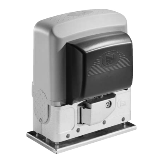
Gearmotor The BK2200T ratiomotor is designed and built by CAME CANCELLI AUTOMATICI S.p.A. and it meets the safety standards in force. The case consists partly of cast aluminium, inside of which operates the non-reversible electromechanical gearmotor, and partly of a covering in ABS plastic inside of which is an electronic card, the transformer and the emergency battery holder. -
Page 5: Parts Description
Parts description GEARMOTOR UNIT 1 - Gearmotor 2 - Board cover support 3 - End-stop flaps 4 - Electric board front cover 5 - Release door 6 - Base plate 7 - Securing screws 8 - Plates for securing screws 9 - Nuts CONTROL PANEL 1 –... -
Page 6: Installation
Installation Installation must be carried out by expert qualified personnel and in full observance of regulations in force. Preliminary checks Before proceeding with the installation, it is necessary to: • Make sure the door is rigid and compact and that the sliding wheels are well oiled and in good condition. •... - Page 7 1 – Gearmotor 6- Flashing light indicating door movement 2 – ZTC/ZT6C control panel 7- Antenna 3- Limit-switch tabs 8- Safety photocells 4- Rack 9- Photocell column 5- Key-operated selector switch 10- Closure stop 11- Sensitive edge Motor to base anchorage The following applications are only examples, as the space required for unit installation and the accessories vary depending on dimensions and therefore it is up to the installer to select the best solution.
-
Page 8: Unit Installation
Unit installation During the initial phase of installation, the feet should protrude by 5-10 mm. in order to allow for alignment, anchorage of the rack and further adjustments. Perfect alignment with the guide rail is made possible by the (paten-ted) built-in regulation system, which consists of: - slots for horizontal adjustment;... - Page 9 Attaching the switch tabs Position the limit-switch tabs (whose positions determine the limits of gate travel) on the rack. Note: do not allow the gate to strike the mechanical stops in the open or closed positions. Manual release of the gearmotor To open the access door, insert the key A, push down and rotate clockwise.
-
Page 10: Electrical Connections
Electrical connections Connection for gear motor, limit switch or encoder - Open the motor and unscrew the protection box; - Drill the protection box and pass through the cables from the external control panel Gearmotor end-stop assembly already connected for installation on the left-hand side seen from inside. - Page 11 Alterations to the electric connections for installing a gearmotor on the right For right-hand installation: - reverse FA-FC of the end stops on the terminal board; - reverse the U-V phases of the motor on the terminal board. ZT6/ZT6C FC FA F E1 EX...
-
Page 12: Safety Instructions
Safety instructions Important safety instructions This product must only be employed for its originally intended use. Any other use is wrong and potentially dangerous. The manufacturer cannot be held liable for any damages resulting from wrongful, erroneous or negligent uses. Avoid working close to the hinges or other moving mechanical parts. -
Page 13: Periodic Maintenance
Maintenance Periodic maintenance Periodic maintenance to be carried out by the end-user is as follows: wipe clean the glass surface of the photocells; check that the safety devices work properly; remove any obstructions. We suggest checking the state of lubrication and tightness of the anchoring screws on the operator. -To check the efficiency of the safety devices, move an object in front of the photocells when gate is closing. -
Page 14: Extraordinary Maintenance
Periodic maintenance log for end-user (every 6 moths) Signature Date Notes Extra-ordinary maintenance The following table serves to note down any extraordinary maintenance, repairs or improvements performed by specialised firms. N.B.: Any extraordinary maintenance must be performed by specialised technicians. Extra-ordinary maintenance log Installer's stamp Product name... - Page 15 UNI EN ISO 14001 standard to ensure environmental protection. Please help us to safeguard the environment. At CAME we believe this to be one of the fundamentals in its market operations and development strategies. Just follow these short disposal instructions: DISPOSING OF THE PACKAGING The components of the packaging (i.e.
- Page 16 HR • Za sve dodatne informacije o poduzeću, proizvodima i tehničkoj podršci: UK • Для отримання будь-якої іншої інформації про компанію, продукцію та технічну підтримку: www. came.com www. came.com CAME Cancelli Automatici S.p.a. CAME Cancelli Automatici S.p.a. Via Martiri Della Libertà, 15 31030 Dosson Di Casier...
Need help?
Do you have a question about the BK-2200T and is the answer not in the manual?
Questions and answers