Table of Contents
Advertisement
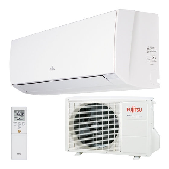
AIR CONDITIONER
Wall Mounted Type
1. SAFETY PRECAUTIONS
•
Be sure to read this Manual thoroughly before installation.
•
The warnings and precautions indicated in this Manual contain important information
pertaining to your safety. Be sure to observe them.
•
Hand this Manual, together with the Operating Manual, to the customer. Request the
customer to keep them on hand for future use, such as for relocating or repairing the
unit.
Indicates a potentially or imminently hazardous situation
WARNING
which, if not avoided, could result in death or serious injury.
Indicates a potentially hazardous situation that may result in
CAUTION
minor or moderate injury or damage to property.
• Installation of this product must be done by experienced service technicians or profes-
sional installers only in accordance with this manual. Installation by non-professional
or improper installation of the product might cause serious accidents such as injury,
water leakage, electric shock, or fi re. If the product is installed in disregard of the
instructions in this manual, it will void the manufacturer's warranty.
• Do not turn on the power until all work has been completed. Turning on the power
before the work is completed can cause serious accidents such as an electric shock
or a fi re.
• If refrigerant leaks when you are working, ventilate the area. If the leaking refrigerant
is exposed to a direct fl ame, it may produce a toxic gas.
• Installation must be performed in accordance with regulations, codes, or standards for
electrical wiring and equipment in each country, region, or the installaton place.
• Do not use means to accelerate the defrosting process or to clean, other than those
recommended by the manufacturer.
• Do not pierce or burn.
• Read carefully all of safety information written in this manual before you install or use
the air conditioner.
• Install the unit by following local codes and regulations in force at the place of
installation, and the instructions provided by the manufacturer.
• This unit is part of a set constituting an air conditioner. The unit must not be installed
alone or be installed with non-authorized device by the manufacturer.
• Always use a separate power supply line protected by a circuit breaker operating on all
wires with a distance between contact of 3 mm for this unit.
• To protect the persons, earth (ground) the unit correctly, and use the power cable
combined with an Earth Leakage Circuit Breaker (ELCB).
• The units are not explosion proof, and therefore should not be installed in explosive
atmosphere.
• To avoid getting an electric shock, never touch the electrical components soon after
the power supply has been turned off. After turning off the power, always wait 5 min-
utes or more before you touch the electrical components.
• This unit contains no user-serviceable parts. Always consult experienced service
technicians for repairing.
• When moving or relocating the air conditioner, consult experienced service technicians
for disconnection and reinstallation of the unit.
• Do not place any other electrical products or household belongings under indoor unit
or outdoor unit. Condensation dripping from the unit might get them wet, and may
cause damage or malfunction of your property.
• Be careful not to scratch the air conditioner when handling it.
• After installation, explain correct operation to the customer, using the operating manual.
WARNING
CAUTION
INSTALLATION MANUAL
Contents
1.
SAFETY PRECAUTIONS .................................................................. 1
2.
ABOUT THE UNIT ............................................................................. 1
3.
GENERAL SPECIFICATION ............................................................. 2
4.
ELECTRICAL REQUIREMENT ......................................................... 2
5.
SELECTING THE MOUNTING POSITION ....................................... 2
6.
INSTALLATION WORK ..................................................................... 3
7.
ELECTRICAL WIRING ..................................................................... 5
8.
FINISHING ........................................................................................ 5
9.
FRONT PANEL REMOVAL AND INSTALLATION ............................. 6
10. TEST RUN ......................................................................................... 6
11. REMOTE CONTROLLER INSTALLATION ........................................ 6
12. OPTIONAL KIT INSTALLATION (OPTION) ....................................... 6
13. INSTALLATION WORK ..................................................................... 7
14. FUNCTION SETTING........................................................................ 9
15. CUSTOMER GUIDANCE ................................................................ 10
16. ERROR CODES ...............................................................................11
2. ABOUT THE UNIT
2.1. Precautions for using R410A refrigerant
The basic installation work procedures are the same as conventional refrigerant (R22)
models.
However, pay careful attention to the following points:
Since the working pressure is 1.6 times higher than that of conventional refrigerant
(R22) models, some of the piping and installation and service tools are special. (See
the table below.)
Especially, when replacing a conventional refrigerant (R22) model with a new refrigerant
R410A model, always replace the conventional piping and flare nuts with the R410A piping
and fl are nuts.
Models that use refrigerant R410A have a different charging port thread diameter to pre-
vent erroneous charging with conventional refrigerant (R22) and for safety. Therefore,
check beforehand. [The charging port thread diameter for R410A is 1/2 inch.]
Be more careful that foreign matter (oil, water, etc.) does not enter the piping than with
refrigerant (R22) models. Also, when storing the piping ,securely seal the opening by
pinching, taping, etc.
When charging the refrigerant, take into account the slight change in the composition of
the gas and liquid phases. And always charge from the liquid phase where refrigerant
composition is stable.
2.2. Special tools for R410A
Tool name
Pressure is high and cannot be measured with a conven-
tional (R22) gauge. To prevent erroneous mixing of other
Gauge manifold
refrigerants, the diameter of each port has been changed.
It is recommended the gauge with seals -0.1 to 5.3 MPa
(-1 to 53 bar) for high pressure.
-0.1 to 3.8 MPa (-1 to 38 bar) for low pressure.
To increase pressure resistance, the hose material and base
Charge hose
size were changed.
A conventional vacuum pump can be used by installing a
Vacuum pump
vacuum pump adapter.
Gas leakage detector
Special gas leakage detector for HFC refrigerant R410A.
Copper pipes
It is necessary to use seamless copper pipes and it is desirable that the amount of residual
oil is less than 40 mg/10 m. Do not use copper pipes having a collapsed, deformed or
discolored portion (especially on the interior surface). Otherwise, the expansion value or
capillary tube may become blocked with contaminants.
As an air conditioner using R410A incurs pressure higher than when using R22, it is
necessary to choose adequate materials.
Do not use the existing (for R22) piping and fl are nuts.
If the existing materials are used, the pressure inside the refrigerant cycle will rise and
cause failure, injury, etc. (Use the special R410A materials.)
When installing and relocating the air conditioner, do not mix gases other than
the specifi ed refrigerant (R410A) to enter the refrigerant cycle.
If air or other gas enters the refrigerant cycle, the pressure inside the cycle will rise to
an abnormally high value and cause failure, injury, etc.
PART No. 9333005072
Contents of change
WARNING
En-1
Advertisement
Table of Contents

Related Manuals for Fujitsu ASYG14LMCB


Summary of Contents for Fujitsu ASYG14LMCB
-
Page 1: Table Of Contents
AIR CONDITIONER INSTALLATION MANUAL Wall Mounted Type PART No. 9333005072 Contents SAFETY PRECAUTIONS ..............1 ABOUT THE UNIT ................1 GENERAL SPECIFICATION ............. 2 ELECTRICAL REQUIREMENT ............2 SELECTING THE MOUNTING POSITION ........2 INSTALLATION WORK ..............3 ELECTRICAL WIRING ..............5 FINISHING .................. -
Page 2: General Specification
2.3. For authorized service personnel only 3.1. Type of copper pipe and insulation material CAUTION WARNING Refer to the installation manual for the outdoor unit for description of allowable pipe • For the air conditioner to operate satisfactorily, install it as outlined in this installation length and height difference. -
Page 3: Installation Work
6.4. Installing the wall hook bracket • Do not use the unit for special purposes, such as storing food, raising animals, grow- ing plants, or preserving precision devices or art objects. • It can degrade the quality of the preserved or stored objects. •... - Page 4 (4) Protect the pipes by pinching them or with tape to prevent dust, dirt, or water from For left outlet piping, entering the pipes. cut off the piping outlet cutting groove Check if [L] is flared uniformly with a hacksaw. and is not cracked or scratched.
-
Page 5: Electrical Wiring
Tightening torque [N·m (kgf·cm)] 7. ELECTRICAL WIRING M4 screw 1.2 to 1.8 (12 to 18) 7.1. Wiring system diagram CAUTION • Match the terminal block numbers and connection cable colors with those of the WARNING outdoor unit. Erroneous wiring may cause burning of the electric parts. •... -
Page 6: Front Panel Removal And Installation
[Operation method] 9. FRONT PANEL REMOVAL AND INSTALLATION • For the operation method, refer to the operating manual. • The outdoor unit, may not operate, depending on the room temperature. In this Intake grill removal Intake grill installation case, keep on pressing the MANUAL AUTO button of the indoor unit for more than Open the intake While holding the 10 seconds. -
Page 7: Installation Work
Do not connect power supply with the terminal. Detail view INDOOR UNIT Cover TERMINAL INSTALLATION WORK 13.1. Remote controller cord modifi cation (1) Use a tool to cut off the terminal on the end of the remote controller cord, and then remove the insulation from the cut end of the cord. - Page 8 (5) While pulling the control box towards you, remove in the right direction. 13.3.4. Installing control box • Do not remove the thermistor. (1) Set the control box toward the bottom so that it touches the motor cover from the •...
-
Page 9: Function Setting
14. FUNCTION SETTING Perform the “FUNCTION SETTING” according to the installation conditions using the remote controller. CAUTION • Confi rm whether the wiring work for Outdoor unit has been fi nished. • Confi rm that the cover for the electrical enclosure on the outdoor unit is in place. •... -
Page 10: Customer Guidance
Remote controller custom code CAUTION (Only for wireless remote controller) The indoor unit custom code can be changed. Select the appropriate custom code. After turning off the power, wait 10 seconds or more before turning on it again. (♦... Factory setting) The Function Setting does not become active unless the power is turned off then on Function again. -
Page 11: Error Codes
• Sub-cool Heat Ex. gas inlet 16. ERROR CODES temp. sensor error ● ● ◊ • Sub-cool Heat Ex. gas outlet If you use a wireless remote controller, the lamp on the photo detector unit will output error temp. sensor error codes by way of blinking patterns.