Table of Contents
Advertisement
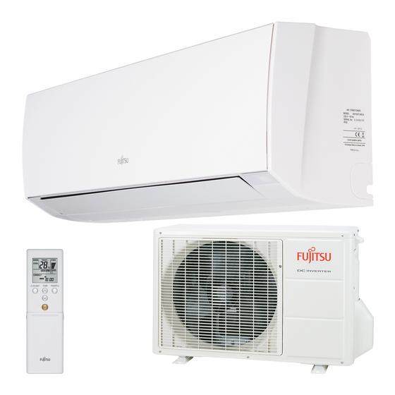
SPLIT TYPE
ROOM AIR CONDITIONER
WALL MOUNTED TYPE
Indoor unit
ASYG14LMCB AOYG14LMCBN
CONTENTS
SPECIFICATIONS. . . . . . . . . . . . . . . . . . .
DIMENSIONS . . . . . . . . . . . . . . . . . . . . . .
REFRIGERANT SYSTEM DIAGRAM. . . .
CIRCUIT DIAGRAM . . . . . . . . . . . . . . . . .
INDOOR PCB CIRCUIT DIAGRAM . . . . .
ERROR DETECTION . . . . . . . . . . . . . . .
PARTS (INDOOR UNIT) . . . . . . . . . . . . .
PARTS (OUTDOOR UNIT) . . . . . . . . . . .
ACCESSORIES . . . . . . . . . . . . . . . . . . .
Outdoor unit
1
2
3
4
5
9
11
13
17
19
Advertisement
Table of Contents

Subscribe to Our Youtube Channel
Related Manuals for Fujitsu ASYG14LMCB


Summary of Contents for Fujitsu ASYG14LMCB
-
Page 1: Table Of Contents
WALL MOUNTED TYPE Indoor unit Outdoor unit ASYG14LMCB AOYG14LMCBN CONTENTS SPECIFICATIONS....DIMENSIONS ..... . -
Page 2: Specifications
SPECIFICATIONS ELECTRICAL DATA NOISE LEVEL High 44 dB TYPE Cool & heat inverter INDOOR UNIT ASYG14LMCB Medium 40 dB INDOOR UNIT Cooling AOYG14LMCBN 33 dB OUTDOOR UNIT COOLING CAPACITY 4.20 kW Quiet 25 dB High 44 dB HEATING CAPACITY 5.40 kW... -
Page 3: Dimensions
DIMENSIONS INDOOR UNIT 840 mm 203 mm Drain hose Diameter Outside Inside : 13.8 mm OUTDOOR UNIT 290 mm 790 mm 540 mm 2013.09.12... -
Page 4: Refrigerant System Diagram
REFRIGERANT SYSTEM DIAGRAM Heat exchanger (indoor unit) 2-Way valve 3-Way valve Compressor Refrigerant pipe diameter Liquid : 1/4" (6.35 mm) Muffler Gas : 3/8" (9.52 mm) Strainer Refrigerant direction 4-Way valve Cooling Expansion valve Heating Heat exchanger (outdoor unit) Strainer 2013.09.12... -
Page 5: Circuit Diagram
UTY-TWBXF Wired remote control (Option) Communication PCB 1 2 3 4 5 CNC01 CIRCUIT DIAGRAM Ex. out (Option) Error status CNB02 Ex. out (Option) CNB01 To main PCB Operation status CND01 CNA01 Ex. in (Option) INDOOR UNIT OUTDOOR UNIT Reactor Compressor CN201 Orange... -
Page 6: Indoor Pcb Circuit Diagram
INDOOR PCB CIRCUIT DIAGRAM EARTH TERMINAL CONTROL UNIT EZ-0131GHSE OUTDOOR UNIT TERMINAL FAN MOTOR SC25-05WSA WHITE THERMISTOR BLACK ( PIPE TEMP. ) BLACK BLACK B5 ( 6-5 ) B-XARK B4B-PH-K-S BLACK THERMISTOR WHITE WHITE BLACK YELLOW ( ROOM TEMP. ) BLUE LOUVER ORANGE... - Page 7 INDOOR UNIT MAIN PCB K12JY-130FHSE-C1 FC51FL x 2 340V 0.6A - 10mH SC25-05WSA SS21V-R060330 20*20*18 BLACK S1NBC60 WHITE TERMINAL 3.15A 4700p LLC-1 250V 470V <E> RF101L2S <LE-MX> <TNR> 15V-2 4700p ST03D-200 <E> 220/ <1/8W> 330/ BLm18 1000p 1.0k RF101L2S <BD102> UL1015 <E>...
- Page 8 INDOOR UNIT INDICATOR PCB K12JZ-1200HSE-D0 D201 SL I-343 CN201 GREEN D202 SL I-343 S7B-PH-K-S ORANGE D203 SL I-343 GREEN SW201 KSHC611BT I C201 R202 GP1UM261R <1/4W> + C202 C203 <B> 2013.09.04...
- Page 9 390V CN301 T301 D303 JM303 SJH20-09WSF SW1614-1 RF101L2S R301 C302 390k 1000p R309 C306 <1/4W> <E> TO MAIN PCB 100/ R302 <1/10W> <1/4W> D301 UF4007 + C301 D302 RF101L2S 450V R306 I C301 1.0k LNK603 R303 R304 C311 <1/10W> 100/ BP_M R305 C305...
-
Page 10: Outdoor Pcb Circuit Diagram
OUTDOOR PCB CIRCUIT DIAGRAM INVERTER ASSEMBLY EZ-01317HUE EMI FILTER ZCAT2132-1130 TO INTDOOR UNIT W103 COMPRESSOR UL1015 UL1015 5A - 250V AWG14 AWG20 BLACK BLACK UL1015 WHITE AWG14 W100 WHITE UL1015 BLACK AWG20 UL1015 REACTOR UL3271 AWG16 SERIAL WHITE AWG20 W102 BLACK UL1015 CN30... - Page 11 OUTDOOR UNIT MAIN PCB K10CT-130EHUE-C1 F100 C100, C101 660uF / 450V x 2 250V R200 POWER SOURCE L300 REACTOR I C200 <1/2W> CAL45VB470K AC230V D102 AOYG09,12LMCBN D100, D101 50Hz UF4007 AOYG09,12LMCBN : SC-10-55JH FSBS15CH60 AOYG09,12LMCBN : D15XB60 x 2 D200 - D202 W7 W8 W9 WHITE AOYG14LMCBN...
-
Page 12: Error Detection
ER R OR D ETEC TION INDOOR UNIT REMOTE CONTROL If you use a wireless remote control, the lamp on the photo detector unit will output error codes by way of blinking patterns. OPERATION indicator lamp (green) If you use a wired remote control, error codes TIMER indicator lamp (orange) will appear on the remote control display. - Page 13 OUTDOOR UNIT Indicator lamp Error Discharge temperature error 0.5 second on / 0.5 second off IPM overcurrent protection 0.1 second on / 0.1 second off Thermistor error CT error 2.0 second on / 2.0 second off 0.1 second on / 2.0 second off Compressor location error 5.0 second on / 5.0 second off Fan error...
-
Page 14: Parts (Indoor Unit)
Remote Control 9319208008 Remote Control Holder 9318912005 Electric Filter Holder 9332911008 Air Clean Filter Assy 9317250009 Air Filter 9332875010 Front Panel Sub Assy (FUJITSU) 9332994001 Intake Grille (FUJITSU) 9333052007 Wire Cover 9332894004 Louver with Shaft cover 9333353005 Wire shield Diffuser Assy... - Page 15 Box shield assy Ref. Description Part number Control Box 9332892000 Main PCB 9709427200 Terminal 9900720001 Display Assy 9709430019 Room Thermistor Holder 9332868005 Thermistor Assy 9900714024 Cover shield INDOOR UNIT Earth terminal Control box 2013.09.24...
- Page 16 INDOOR UNIT Evaporator Ref. Description Part number Evaporator Total Assy 9332989014 Fan Motor 9603269005 Crossflow Fan Assy 9316830004 Bearing C Assy 9306628017 Casing Assy 9333009001 2013.09.24...
- Page 17 INDOOR UNIT Casing assy Ref. Description Part number Casing 9332890006 Motor Holder L/R 9332859003 Cable Guide 9332903003 Casing Cover F 9332909005 Casing Cover B 9332908008 R and L Louver A 9332891003 Step Motor 9900790004 Step Motor 9900790011 Fan Guard 9332905007 Drain Cap 9316177017 Drain Hose Assy...
-
Page 18: Parts (Outdoor Unit)
PARTS OUTDOOR UNIT Ref. Description Part number Thermistor Holder 9313954031 Protective Net 9332492002 Top Panel Assy 9318464023 Front Panel Assy 9318463026 Emblem 9319151007 Valve bracket Cabinet Left Assy 9318461015 Grip 9317588003 Switch Cover Assy 9318499001 Cabinet Right Assy 9318462005 Motor bracket Reactor Assy 9900611019 Fan Motor... - Page 19 Sealed panel OUTDOOR UNIT Terminal bracket Ref. Description Part number Heater Unit Assy 9900616014 Condenser Total Assy 9317089098 Inverter case Compressor Assy 9317117005 2-way Valve Assy 9332371000 3-way Valve Sub Assy 9317109055 4-way Valve Assy 9315311092 Solenoid 9970110047 Pulse Motor Valve Assy 9332368048 Expansion Valve Coil 9970095030...
-
Page 20: Accessories
ACCESSORIES INDOOR UNIT OPTIONAL PARTS Name and Shape Part number Name and Shape Part number Name and Shape Wired remote control Bracket Panel Seal A 9304536000 UTY-RVNYM 9332882018 Tapping screw 0700076046 Wired remote control (M4 x 25 mm) UTY-RNNYM Remote Control 9319208008 Tapping screw 0700019036... - Page 21 1309G4251...
Need help?
Do you have a question about the ASYG14LMCB and is the answer not in the manual?
Questions and answers
It doesn't warm up