
Subscribe to Our Youtube Channel
Related Manuals for usi CSL2700


Summary of Contents for usi CSL2700
- Page 1 CSL2700 ROLL LAMINATOR O W N E R S M A N U A L C A L L T O L L F R E E 1-800-282-9290 Free Customer Lifetime Service Tech M-F 8am to Support 6pm EST...
-
Page 2: Equipment Warranty
PLEASE DO NOT DESTROY THE SHIPPING CARTON! USI urges you to store the original carton in which your laminator was shipped. Should you ever need to return your laminator to our repair and service center, it is best repacked in the original carton to avoid damage during transport. Our special foam filled carton ensures the laminator’s safe transit to our service facility. - Page 3 IMPORTANT: This manual is copyright protected by USI, Inc. in accordance with the laws and requirements of the United States Government. Any reproduction of this manual, in part or in full, without the written permission of USI, Inc. constitutes a violation of the U.S. copyright laws and is subject to prosecution.
-
Page 4: Table Of Contents
taBlE oF contEntS chapter 1 — Preparation Part I laminator Introduction ......... 5,6 Part II Work area . -
Page 5: Safety Precautions
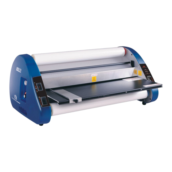
IntrodUctIon USI roll laminators are uniquely designed and engineered to be user friendly, reliable and virtually trouble free. USI’s modular construction makes them easy to maintain and repair. all equipment controls are basic in design, functional... - Page 6 cSl 2700 Feature location: tension adjusting Knobs color coded Supply mandrel (holds film) Heat Guard Side Housing temperature adjustment Knob Built-in Handles Heat on/oFF Switch motor drive Switch Paper Guide Feed tray Heat Shoes (Behind Heat Guard) Film temperature Guide thermometer...
-
Page 7: Work Area
4 sides. If the laminator is back against a wall, the laminating film may back up and jam the equipment. a USI laminator cabinet is an excellent choice for a work area. It can easily be moved and provide sufficient storage for film in the cabinet below. -
Page 8: Unpacking
UnPacKInG YoUr lamInator Your laminator comes packed in one carton. It contains (1) laminator, (1) heat guard, (1) top supply mandrel, (1) bottom supply mandrel, (1) threading board, (1) feed table with guide, and this operation and maintenance manual. (See diagram page 6) First, open the box. -
Page 9: Loading Film
loadInG FIlm COLOR-CODED LAMINATORS & FILM: Select the two rolls of laminating film that you wish to use. Both rolls of film should be of the same size, type and thickness. next, take the bottom supply mandrel (marked with the blue color-code) and insert it into the roll of film so the blue end of the mandrel matches the blue end of the film roll. -
Page 10: Threading Diagram
Note: When loading your laminating film, check for film splices. These rolls will be clearly marked. Splices are not common, but are unavoidable. If you find a spliced roll, place it in the top position on the laminator so that the splice can be monitored carefully. - Page 11 thread the top roll of film under the idler roller as shown in the threading diagram on previous page (see Figure 10-4). Pull the film down so that the films lead edge is below the lower heat shoe. next thread the bottom roll of film under the lower idler bar pulling film upward until it is even with the top heat shoe (the film will overlap).
-
Page 12: Heat Settings
HEat SEttInGS Prior to laminating, allow the machine to pre-heat at least 15 minutes in order to stabilize the temperature. temperature settings depend on the film type being used. the temperature is preset at the factory, but may require adjustment depending on what type of film you are using. - Page 13 tEnSIon to adjust tension for upper and lower rollers, the laminator must be loaded and heated. remove the heat guard and feed tray. loosen both tension control knobs by turning counterclockwise until there is no tension on upper or lower film rolls. Photos 13-1, 13-2. Film should pull freely.
- Page 14 rEloadInG a nEW roll oF FIlm on a Hot lamInator allow the old film to run to a point just before it pulls off the cardboard cores.turn the drive switch to “oFF.” cut the film web with a blade so that approximately 5” of film extends beyond the idler bar. Photo 14-1. CAUTION: When using a sharp object to cut film (blade or shears), avoid contact with heat shoes or rubber rollers.
-
Page 15: Cleaning The Heat Shoe
Photo 15-3 Wipe clean with the sponge pad and cleaning fluid from USI’s laminator cleaning Kit. NOTE: Use cleaning fluid sparingly. Do not allow to “run” onto wiring or into “ends”... -
Page 16: Upper Heat Shoe Removal
UPPEr HEat SHoE rEmoval InStrUctIonS 1. Unplug laminator and allow it to cool to room temperature. 2. remove the right side housing (Figure 16-3) by unscrewing four allen head screws. 3. Unscrew wiring retainer. note its orientation and location of wires for reassembly. It is very important that wires are routed correctly or damage to machine may occur. -
Page 17: Reinstall The Heat Shoe
to rEInStall tHE HEat SHoE 1. Be sure laminator is unplugged. 2. Guide heat shoe wires exiting from the right end of the heat shoe through the slot in the right side of frame. 3. lower the right end of the heat shoe onto its bracket first, then lower the left end and lock in place. -
Page 18: Removing The Rubber Rollers
rEmovInG tHE rUBBEr rollErS NOTE: Only remove rollers if they are cut or in poor condition. NOTE: The following procedure removes all 4 rollers. In certain instances, it is not necessary to remove all 4 rollers, therefore, remove as required. STEP 1: remove all film from laminator. - Page 19 STEP 7: to remove the upper roller, slide the roll shaft out of the roller and then lift the top rubber rollers from the laminator (top laminating roller shown). Photos 19-1 and 19-2 Photo 19-1 STEP 8: loosen the set screws of the lower roller sprockets (laminating roller shown) Photo 19-3.
- Page 20 STEP 11: to install a new roller or replace the original roller, reverse the removal procedure. Be sure to properly reposition the sprockets and align the chain. all three sprockets should be in line with each other. Since the motor sprocket was not removed, use it as a guide for alignment of the pull roll and laminating roll sprockets.
-
Page 21: Pressure Settings
PrESSUrE the pressure settings for the rubber rollers on USI laminators are preset at the factory and should not require adjusting. In most cases, it is necessary to adjust pressure after the rollers have been removed for service. (Generally this is the only time an adjustment is required.) - Page 22 lamInator lUBrIcatIon oil the drive chain once every six months with a light weight oil. to avoid binding of the laminating and pull rollers, periodically oil the black plastic bushings. Bushings are located at the end of each roller. to gain access remove side housings. Photo 22-1 Photo 22-2 NOTE: Any type of light oil (i.e.
-
Page 23: Cleaning Friction Studs
clEanInG FrIctIon StUdS If film rolls begin to shudder or squeak, cleaning of tension assembly is required. STEP 1: remove the film rolls. STEP 2: remove the right side housing. STEP 3: dissemble the friction stud by unfastening and removing the knob. Photo 23-1. Photo 23-1 STEP 4: remove the spring, metal washer, leather... -
Page 24: Sprockets
tIGHtEnInG SProcKEtS laminating roll STEP 1: Pull roll Sprocket Sprocket remove the right side housing. locate loose sprocket. Each sprocket has an allen set screw located along the outer edge. If the set screw loosens, it will allow the sprocket to spin on the roll motor Sprocket shaft, causing the rollers to slip. - Page 25 THERMAL FUSE REPLACEMENT - CSL Roll Laminators equipped with DualThermalFuse 1. Unplug the laminator from power supply and allow it to cool to room temperature. Caution: never attempt to service a machine that is energized! 2. Remove the right side housing by removing four Allen head screws on the side of the machine using a 3mm Allen wrench and then pulling the cover off gently.
-
Page 26: Thermistor Replacement
tHErmIStor rEPlacEmEnt 1. Unplug the laminator from power supply and allow it to cool to room temperature. Caution: never attempt to service a machine that is energized! 2. Remove the thermometer and temperature adjustment knob. Note: the temperature adjustment knob is retained by an Allen set screw located along the outer edge of the knob, do not try to remove the knob without first loosening the set screw;... -
Page 27: Trouble Shooting
troUBlE SHootInG common EXamPlES oF Poor lamInatInG . . . and their causes. FIlm not BondInG to SUBJEct or to ItSElF at SEalEd EdGES causes: 1. the heat is set too low. 2. Film tension is too tight. 3. Bottom roll of film is threaded incorrectly. 4. -
Page 28: Threading Diagram For 1" Mandrels
troUBlE SHootInG common EXamPlES oF Poor lamInatInG . . . and their causes. (continued) HEat doES not WorK and rEd IndIcator lIGHt doES not IllUmInatE 1. check wiring of the laminator. refer to wiring diagram on page 28 and 29. 2. -
Page 31: Parts List
PartS lISt PART # COMPONENT DESCRIPTION Left Zone A4536 MOTOR CONTROL BRACKET S6102 MOTOR CONTROL BOARD (N020) A5096 JONES SOCKET FOR FOOT SWITCH (N029) A5510 HEAT SWITCH LIGHTED 2002 A5511 DRIVE SWITCH 2002 G5533 KEY LOCK SWITCH A5846 TEMPERATURE CONTROL KNOB (N021) A5847 TERMINAL BLOCK NUMBERED W/JUMPER A9800B... - Page 32 SPLIT LOCK WASHER FOR REINFORCING BAR A4746 WIRING HARNESS CLAMP A5553 BLIND RIVET AD64BS (14V) A3970 USI THREADING BOARD G4511 ARL 27 SOCKET HEAD CAP SCREW, LOWER HEATSHOE LEFT A4505 TIE MOUNTING PAD A4508 NYLON SPACER, MOTOR CONTROL OR TIMER BOARDS...
- Page 33 notES...
- Page 34 Revised: 5-1-17...
Need help?
Do you have a question about the CSL2700 and is the answer not in the manual?
Questions and answers