
Related Manuals for Goalsetter Systems X672


Summary of Contents for Goalsetter Systems X672
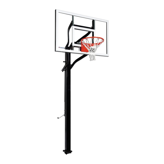
- Page 1 EXTREME SERIES Adjustable Height Goal Systems • X672 • X660 • X560 • X554 • X454 • X448 Installation & Owner’s Instructions Made In The USA...
-
Page 2: Contact Information
GOALSETTER ® , GOALSETTER SYSTEMS ® AND GOALSETTER ® logo are all registered trademarks of Goalsetter Systems, Inc. in the U.S. and/or other countries. ™ and BEST IN BASKETBALL ™ are trademarks of Goalsetter Systems, Inc. This product is covered by various U.S. and Canadian patents, including U.S. -
Page 3: Table Of Contents
Extreme Series Goal System Instructions TABLE OF CONTENTS Contact Information ........2 Thank You . -
Page 4: Thank You
Extreme Series Goal System Instructions THANK YOU! Thank you and congratulations for purchasing a Goalsetter Goal – the finest basketball goal system on the market today! You will discover that Goalsetter is unsurpassed in product innovation, quality and integrity in the basketball equipment industry. -
Page 5: Safety Instructions
Extreme Series Goal System Instructions SAFETY INSTRUCTIONS Failure to follow these safety instructions may result in serious injury or death and/or property damage. • Do not install or use this product unless the instructions within this manual have been carefully read and understood. •... -
Page 6: Ground Anchor Installation
Extreme Series Goal System Instructions GROUND ANCHOR INSTALLATION Contacting buried utilities may cause serious injury or death. Before you start digging, always contact your local One-Call system to help prevent personal injury, interruption of services, environmental accidents or job delays. Electric lines can shock or electrocute. -
Page 7: Ground Anchor Placement
Extreme Series Goal System Instructions GROUND ANCHOR PLACEMENT IMPORTANT – When preparing for ground Playing Surface 6" (152 mm) anchor, allow at least 6" (152 mm) from all sides all sides of ground anchor to wall of hole to allow for sufficient concrete fill around anchor. -
Page 8: Installation
Extreme Series Goal System Instructions GROUND ANCHOR INSTALLATION Dig Hole – When installing goal into a hard- 18" (0.5m) Diameter surfaced area, a minimum of a 18" x 18" (0.5 x 0.5 m) area of the hard surface will need to be removed. -
Page 9: Goal Assembly
Extreme Series Goal System Instructions GOAL ASSEMBLY IMPORTANT: Concrete must cure a minimum of 48 hours before installing goal. IMPORTANT: Safe assembly of the goal requires two to three people in good physical condition and capable of lifting 80-100 lbs (36-45 kg) each. -
Page 10: Hardware Identification
Extreme Series Goal System Instructions HARDWARE IDENTIFICATION Anchor Hinge Bolt (All Models) Black Touch-Up Paint Assembly Lock Plate (All Models) Ground Anchor Bolt Assembly (All Models) Jack Lower Pivot Bolt Assembly NOTE: Refer to page 12-15 for descriptions and quantities. www.goalsettersystems.com 800.362.GOAL (4625) -
Page 11: Hardware Identification
Extreme Series Goal System Instructions HARDWARE IDENTIFICATION Extension Arm Bolt Assembly 8" (X448 & X454) 10" (X554 & X560) 11" (X660 & X672) Jack Upper Pivot Bolt Assembly 8" (X448 & X454) 10" (X554 & X560) 11" (X660 & X672) Backboard Bolt Assembly 8"... -
Page 12: Goal Specifications
GOAL SPECIFICATIONS Model Pole Backboard Weight Weight Height Size Size With Acrylic With Glass Range (A) X672 6" x 6" 42" x 72" 475 lbs. 535 lbs. 7'-10' X660 6" x 6" 38" x 60" 460 lbs. 515 lbs. 7'-10' X560 5"... - Page 13 Extreme Series Goal System Instructions 5" & 6" - 10", 4"- 6-1/2" Playing Surface 800.362.GOAL (4625) www.goalsettersystems.com...
-
Page 14: Parts List
Extreme Series Goal System Instructions PARTS LIST Hardware Backboard 4 places Assembly –X672 –X660 –X560 –X554 2 places –X454 –X448 Upper Extension Arm 15 16 Rim & Net Assembly Hardware Hardware Hardware Rim Backplate – 4" poles only Lower Jack... - Page 15 EXTREME SERIES PARTS DESCRIPTION – page 15 X672 X660 X560 X554 X454 X448 DESCRIPTION – – – – Ground Anchor (6" x 6") – – – – Ground Anchor (5" x 5") – – – – Ground Anchor (4" x 4") –...
-
Page 16: Pole Assembly
Extreme Series Goal System Instructions POLE ASSEMBLY Step 1: Remove five plastic plugs from threaded holes in ground anchor. Also remove hinge bolt 3 and nut (these will be used in Step 3.) NOTE: Use protective padding to protect pole finish. Step 2: Unpack pole. - Page 17 Extreme Series Goal System Instructions POLE ASSEMBLY (continued) Step 7: Attach lower end of jack 9 to bracket on pole 10 with 1/2" x 4" bolt (#6 in parts list), two flat washers, four nylon washers and locknut. NOTE: Jack is packaged with pole on all Extreme models. Hardware Sequence: Bolt passes through flat washer - nylon washer - pole bracket - nylon washer -jack...
-
Page 18: Backboard Attachment
NOTE: X448 and X454 backboard Hardware Sequence for X672 and X660: Bolt passes through flat washer - arm uses two 1/2" bolts and four 5/8" bracket - backboard bracket - arm flat washers for attachment; all bracket - flat washer - locknut. -
Page 19: Goal Alignment
Step 6: Fully tighten five bolts. IMPORTANT: The bolts must pass all the way through the ground anchor plate. If they are recessed within the plate when fully tightened, please contact Goalsetter Systems. 800.362.GOAL (4625) www.goalsettersystems.com... -
Page 20: Rim Attachment
Extreme Series Goal System Instructions RIM ATTACHMENT NOTE: Use all steps of the following instructions to install a reflex rim. To install a static rim, follow all steps except #2 and #6. Step 1: Remove any cardboard edge protectors and protective sheeting from backboard. NOTE: Four steel shouldered bushings 1 are factory installed. -
Page 21: Height Indicator Attachment
Extreme Series Goal System Instructions HEIGHT INDICATOR ATTACHMENT Step 1: Position top of rim 7' above playing surface using crank handle. Measure distance with a tape measure for accuracy. Step 2: Peel 1/2" of backing off the top of the decal. Slip decal under the outer tube on the jack until the 7' line is even with the lower end of the jack tube 1 . -
Page 22: Lubrication
“3-in-1” or lightweight motor oil is recommended. DO NOT use penetrating oil like “WD-40”. Goalsetter has “Maintenance Kits” available which would include a bottle of lubricating oil. Contact Goalsetter Systems, Inc. or your local Goalsetter Dealer for details. www.goalsettersystems.com 800.362.GOAL (4625) -
Page 23: Warranties
Normal deterioration of products due to atmospheric conditions, weather, wear and tear (including paint), or other causes that do not affect functional use are not covered by Goalsetter Systems warranties. All warranties are valid only when product is used in the intended application & when installed according to Goalsetter Systems instructions. - Page 24 Questions? Comments? Contact Us: Phone: 800.362.4625 • Fax: 641.594.3343 Email: info@goalsettersystems.com www.goalsettersystems.com...
Need help?
Do you have a question about the X672 and is the answer not in the manual?
Questions and answers