Table of Contents
Advertisement
Quick Links
Table of Contents
Introduction ................................................................................................................................................... 1
Infrared Gas Analysis (IRGA) ................................................................................................................ 1
Dispersive and Non-Dispersive IRGA .................................................................................................... 2
Photosynthesis Measurement Using IRGA............................................................................................. 2
Technical Information ................................................................................................................................... 3
Main Components of Gas Exchange Systems ........................................................................................ 4
Highlights of CI-340 ............................................................................................................................... 4
General Operating Instructions ...................................................................................................................... 7
Using the Keypad .................................................................................................................................... 7
File Menu ................................................................................................................................................ 8
Installation of the Battery ........................................................................................................................ 9
Interpretation of Parameters .................................................................................................................. 11
System Setup and Calibration ..................................................................................................................... 12
Calendar and Time Setup ...................................................................................................................... 13
Leaf/Air Temperature Sensor ............................................................................................................... 13
Atmospheric Pressure ........................................................................................................................... 13
Flow Rate .............................................................................................................................................. 14
CO2 and H2O General Overview ......................................................................................................... 15
CO2 Zero and CO2 Span Procedure ..................................................................................................... 17
H2O Zero and H2O Span Procedure .................................................................................................... 18
Data Transfer ............................................................................................................................................... 19
Downloading Data ................................................................................................................................ 20
Updating Software ................................................................................................................................ 21
Example of a Data File ......................................................................................................................... 22
Photosynthesis, Transpiration and Stomatal Conductance .......................................................................... 23
Taking Measurements ........................................................................................................................... 23
Closed and Open Systems ..................................................................................................................... 26
Terminology: ............................................................................................................................................... 28
Absolute, Differential and Continuous Mode ....................................................................................... 28
Photosynthesis ...................................................................................................................................... 28
Photosynthetic Active Radiation (PAR) ............................................................................................... 29
Transpiration ......................................................................................................................................... 29
Advertisement
Table of Contents
Troubleshooting

Related Manuals for CID Bio-Science CI-340


Summary of Contents for CID Bio-Science CI-340
-
Page 1: Table Of Contents
Dispersive and Non-Dispersive IRGA ....................2 Photosynthesis Measurement Using IRGA..................... 2 Technical Information ........................... 3 Main Components of Gas Exchange Systems ..................4 Highlights of CI-340 ..........................4 General Operating Instructions ........................7 Using the Keypad ............................ 7 File Menu ..............................8 Installation of the Battery ........................ - Page 2 Stomatal Conductance .......................... 30 Open and Closed Systems ........................30 Calibrating ............................34 DATA DISPLAY SCREENS........................36 GRAPH MODE ............................36 CARE OF THE CI-340 ..........................37 LEAF CHAMBER CARE AND USE ....................38 RECHARGING ............................ 41 EQUATIONS .............................. 44 TROUBLESHOOTING ..........................46 SYSTEM SPECIFICATIONS........................
-
Page 4: Introduction
USB connector. The functions of the CI-340 are described in further detail in Table 1 and the following sections. -
Page 5: Dispersive And Non-Dispersive Irga
CI-340 Operation Manual rev. 6/7/2017 Dispersive and Non-Dispersive IRGA Infrared gas analyzers can be either dispersive or non-dispersive. Dispersive infrared analyzers sequentially apply monochromatic radiation, which determines the concentration of various gas species in a complex mixture of gases. In contrast, non-dispersive analyzers assay the concentration of a particular species of gas. -
Page 6: Technical Information
A built-in microprocessor regulates the airflow rate, which is set by the user. Specifically, the CI-340 is a non-dispersive IRGA in which the infrared light is shone through the gas in the sampling chamber and then focused on a detector. The energy received at the detector is the total energy entering the system minus the energy absorbed by the CO in the sampling chamber. -
Page 7: Main Components Of Gas Exchange Systems
CI-340 Operation Manual rev. 6/7/2017 When initially performing a measurement, the CI-340 takes gas from the inlet or intake where air is coming in through a filter. This air is moved through the pump and then next through the flow sensor where the flow rate is regulated. - Page 8 With fewer components involved, there are fewer errors and less instrument drift. The CI-340 can measure chlorophyll fluorescence and photosynthesis simultaneously, has modular attachments for light and temperature control, CO O supply and chlorophyll fluorescence, as well as addition attachment capabilities for soil respiration and plant canopy photosynthesis measurements.
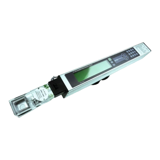
- Page 9 CI-340 Operation Manual rev. 6/7/2017 Figure 2: Parts of the CI-340 CID Bio-Science 1554 NE 3 Phone: +1 (360) 833-8835 sales@cid-inc.com Camas, WA 98607, USA Fax: +1 (360) 833-1914 www.cid-inc.com...
-
Page 10: General Operating Instructions
0.25 lpm if the readings are low. Using the Keypad The keypad for the CI-340 consists of 20 keys to enter commands and data. Figure 3-1 illustrates the keypad. Pressing a key makes a “beeping” sound. A key should be pressed individually each time a command or letter is asked for. -
Page 11: File Menu
These characters are not usable: [ +,-,(,*,/,) ] File Menu The CI-340 has a file system that allows a great range of data to be stored internally. It has been designed to emulate the familiar DOS of personal computers. Note that this menu will not be accessible when there are no files stored in memory;... -
Page 12: Installation Of The Battery
Li-Ion batteries to be simply thrown in the trash. Refer to the RECHARGING chapter for further information on how to take care of the battery and for how to power the CI-340 in the lab without using the Li-ion battery. - Page 13 CI-340 Operation Manual Figure 4: Battery installation: Press the battery toward the contacts. CID Bio-Science 1554 NE 3 Phone: +1 (360) 833-8835 sales@cid-inc.com Camas, WA 98607, USA Fax: +1 (360) 833-1914 www.cid-inc.com...
-
Page 14: Interpretation Of Parameters
CI-340 Operation Manual Interpretation of Parameters (in) The amount of CO (in ppm) at the inlet of the analyzer (out) The amount of CO (in ppm) at the outlet of the leaf chamber (dif) The difference between the CO in and CO out values. -
Page 15: System Setup And Calibration
The system is shipped from the factory calibrated for immediate use. The user can perform most system calibrations if necessary. To start the CI-340, press . After a brief warm-up time, the instrument will display the basic display as follows:... -
Page 16: Calendar And Time Setup
No further calibration is allowed. Atmospheric Pressure The CI-340 pressure sensor is capable of measuring absolute atmospheric pressure. This value is used in calibrations for Photosynthesis, Transpiration and Stomatal Conductance values. The sensor is calibrated at the factory, and normally does not need to be recalibrated. -
Page 17: Flow Rate
Flow Rate The CI-340 is capable of maintaining a steady airflow once the unit begins taking measurements. After the initial warm-up time (one minute), the instrument will generate the entered flow rate to regulate the accuracy of the measurements. -
Page 18: Co2 And H2O General Overview
CI-340 Operation Manual procedure is competed, in a few moments the instrument will reset and return back to the above screen display. CO2 and H2O General Overview H2O and CO2 Zero should be calibrated every week, unless there are very significant changes in ambient conditions or the relative humidity values seem erroneous. - Page 19 CI-340 Operation Manual Figure 6: Configuration using compressed gas. After the system zero is established, use a gas with known concentration of CO to calibrate span. Use the key to skip the “calibrate the span” setting. Use known CO Press the key to proceed.
-
Page 20: Co2 Zero And Co2 Span Procedure
Figure 8: Configuration using Silica Gel for H O calibration CO2 Zero and CO2 Span Procedure Tools required: CI-340, Soda Lime external conditioning tube, filter, hose barbs, a CO2 standard gas ranging from 200-1000 ppm, a t-junction, and a flow regulator. 1. Power on the instrument 2. -
Page 21: H2O Zero And H2O Span Procedure
To verify a successful calibration, take a reading of a known gas. The instrument should read with an accuracy of < ±2%. H2O Zero and H2O Span Procedure Tools required: CI-340, Silica gel external conditioning tube, filter, hose barbs, a H20 standard of known partial pressure, a t-junction, and a flow regulator. 1. Power on the instrument 2. -
Page 22: Data Transfer
Calibrate H2O”. Data Transfer The CI-340 automatically saves data files with a memory capacity of 4 megabytes; older versions have a memory capacity of 2 MB. The memory of the CI-340 during normal use will suffice for approximately CID Bio-Science... -
Page 23: Downloading Data
However, data analysis and presentation can best be done on an external (desktop or laptop) computer. To download data to an external computer, attach the CI-340 USAB Cable to both the CI-340 and the computer’s USB port. -
Page 24: Updating Software
DL.exe. Connect the CI-340 USB cable. Run the DL.exe. program to download code from the computer. Make certain that the the power is on to the CI-340. If the power does not stay on, then press and hold the key on the CI-340 (a constant ‘beep’... -
Page 25: Example Of A Data File
CI-340 Operation Manual Example of a Data File Internal T Flow Pressure leaf 2out 27.5 100.09 2175 31.1 32.8 344.9 333.0 1.09 1.10 3.12 27.5 100.09 2011 31.2 32.9 339.9 328.2 1.23 1.25 2.78 27.5 100.09 2230 31.2 33.1 365.7 337.9... -
Page 26: Photosynthesis, Transpiration And Stomatal Conductance
(°C), and applying the calculation for Equation 4 found in the EQUATIONS chapter. The CI-340 is designed so that measurements can incorporate both absolute and differential readings simultaneously. This instrument can also be configured to operate both open and closed systems. It is important that the CI-340 uses the manufacturer’s current software. - Page 27 The instrument will then utilize all the same operating parameters as the last measurement. The CI-340 utilizes a shift key feature to accommodate many functions it has to offer. To register alpha-characters (such as A, H, R, etc.), use a sequence of the key followed by the respective key to obtain the letter.
- Page 28 CI-301CS and the CI-301LA are used, enter number “5”. If the CI-301AD and the CI-301LA are used, enter number “6”. If all the three accessories are used, enter number “7”. To operate the CI-340 without any accessories, enter number “0”, or just press key.
-
Page 29: Closed And Open Systems
Closed and Open Systems The CI-340 promotes a portable solution to the concept behind open and closed systems. A closed system environment can measure the CO concentration in the chamber over a given period of time. - Page 30 Determine the best size chamber (Table 2) for the measurements to be taken. Proceed to insert and attach the leaf chamber to the CI-340. Refer to the LEAF CHAMBER — CARE AND USE chapter for proper applications of the leaf chamber(s). Then press the key(s) to begin the measurement process.
-
Page 31: Terminology
Almost all commercial plant IRGA systems are of the differential type, because they provide more reliable measurements. The CI-340 is capable of obtaining absolute (single channel absolute, S) and differential (photosynthesis, P) measurements, as well as continuous measurements (continuous photosynthesis, C). -
Page 32: Photosynthetic Active Radiation (Par)
PAR. This spectral range is very similar to the range of light visible by the human eye (390-750 nm). The CI-340 measures PAR with silicon diode sensors mounted near the leaf chamber. The sensor measurement is cosine corrected. -
Page 33: Stomatal Conductance
The term closed or open is used in the sense of whether or not the atmosphere of the leaf- enclosing chamber is renewed during the measurement. The CI-340 supports both open and closed system modes of operation. Early photosynthesis analyzers supported only closed system measurements, but today most systems are open systems. - Page 34 There are several different leaf chambers available for use with leaves and plants, as seen in Figure 5. Each individual chamber is designed to interchange with the CI-340; however, they serve different sizes of the plant element. There are five available sizes of leaf chambers to conduct experiments for the open system method (Table 2).
- Page 35 CI-340 Operation Manual Figure 5: Various different leaf chambers for the CI-340 and the soil respiration chamber. Table 2: Open system chamber sizes and areas. Chamber Type Window Size (W x L Window Area CI-301-: Square 25 x 25 6.25...
- Page 36 Measuring Conifer Needles Using the CI-340: The CI-340 does not have specific conifer or needle chambers as opposed to chambers for broadleaves. The type of chamber selected for measuring conifers will depend on the plant type (average needle length and other characteristics).
-
Page 37: Calibrating
CI-340. If the window is not fully covered, estimate the percentage that is covered and enter that leaf area into the CI-340. If the branch of the plant is inside the chamber (LC-4 or LC-5) the branch does not usually need to be included in the estimated leaf area. - Page 38 The resolution of infrared gas analyzers is directly related to the length of the infrared gas analyzer chamber. The longer the tube to the chamber is, the finer the resolution. In order to help the CI-340 produce repeatable measurements, a single IRGA tube next to the leaf chamber is used to measure CO levels in the air before and after the leaf chamber.
-
Page 39: Data Display Screens
With the use of the CI-510LA (CI-301LA), the response curve of photosynthesis vs. light can be seen by pressing “L” when measuring photosynthesis (that is shift, shift, shift 4). The CI-340 will ask for the number of steps for light response and then will direct the CI-510LA to increase the light intensity from very low to very high in that number of steps. -
Page 40: Care Of The Ci-340
• Do not allow water or excessive moisture to get into the instrument. The CI-340 can measure air with high humidity, but it is highly recommended to avoid such circumstances. In addition, if used in the field environment, please avoid extremely dusty conditions. -
Page 41: Leaf Chamber Care And Use
A chamber without O-rings on the tubes may demonstrate leakage at the CI-340 connection. To attach the chamber to the CI-340, carefully slide the tubes on the chamber into the “head” end of the instrument, aligning the locking screw (from the CI-340) with the mating hole in the chamber. - Page 42 CI-340 Operation Manual Figure 9-1.llustration of a leaf chamber: CI-301LC-2, Wide Rectangular Chamber for an open system. We recommend working in temperature ranges between 5 and 45 ºC for greatest precision. Be sure both sensors are connected to the leaf chamber prior to using. The PAR sensor is extremely sensitive to even subtle changes in the light environment.
- Page 43 CI-340 Operation Manual Figure 9-2. Connecting a leaf chamber to the CI-340. CID Bio-Science 1554 NE 3 Phone: +1 (360) 833-8835 sales@cid-inc.com Camas, WA 98607, USA Fax: +1 (360) 833-1914 www.cid-inc.com...
-
Page 44: Recharging
1. Connect the DC coupler to the CI-340. Align the front end of the DC coupler with the guides on the back of the CI-340, then press and slide the DC coupler into the CI-340 to set it in place. - Page 45 4. Connect the DC coupler to the charger/adapter’s DC terminal. TO DISCONNECT THE CHARGER/ADAPTER 1. Turn the CI-340 off and detach the DC coupler. 2. Disconnect the DC coupler from the charger/adapter. 3. Unplug the charger/adapter and disconnect the power cable from the charger/adapter.
- Page 46 DC to AC inverters, etc. • Use only specified CI-340 products with this charger/adapter. • Do not disassemble the charger/adapter (or DC coupler), and do not expose it to water, shock or vibration, or to direct sunlight.
-
Page 47: Equations
CI-340 Operation Manual EQUATIONS CID Bio-Science Phone: +1 (360) 833-8835 sales@cid-inc.com 1554 NE 3 Camas, WA 98607, USA Fax: +1 (360) 833-1914 www.cid-inc.com... - Page 48 CI-340 Operation Manual CID Bio-Science 1554 NE 3 Phone: +1 (360) 833-8835 sales@cid-inc.com Camas, WA 98607, USA Fax: +1 (360) 833-1914 www.cid-inc.com...
-
Page 49: Troubleshooting
“blank” out the screen. Excessive glare may be the obvious problem • Make sure the accessory cable (if plugged into the CI-340) is in the “OFF” position, towards the instrument, or simply unplug the cable connector. The switch should only be in the “ON”... - Page 50 CI-340 Operation Manual • Make sure to press the key(s) firmly and hold until the “beep” sounds. When the instrument is busy performing a task, it may not respond immediately to a pressed key. • Check to see that the key sequence(s) are valid. Randomness does not guarantee a proper operational instrument.
-
Page 51: System Specifications
CI-340 Operation Manual SYSTEM SPECIFICATIONS CO2 Analyzer: Sensor: Low power Non-Dispersive Infrared Gas Analyzer. No sensitivity to motion Chopping frequency: 1 Hz Source life: 5000 hours Sensor response time: 35 seconds Repeatability: ± 0.1ppm (short term) Sample cell: 100 mm × 10.2 mm (3.94”L × 0.40” Dia) Warm-up time: Approximately 3 minutes Accuracy: <... -
Page 52: Par Sensor
CI-340 Operation Manual Typical Signal: The sensor electronics typically puts out a 0.5V signal for 50% RH, which is amplified to 2.34V and measured with a 16bit ADC. PAR Sensor Sensor Type: Filtered GaAsP photodiode Range: 0 ~ 2500 µmol m Accuracy: ±5 µmol 0-2500 µmol / m2 / sec... -
Page 53: Power Pack
CI-340 Operation Manual POWER PACK The CI-340 Battery Pack is necessary to operate the modules to control light, temperature, CO2 concentration, humidity level and chlorophyll fluorescence measurement. CI-340 Battery Pack (Figure 14-1) includes two rechargeable batteries, AC power supply charger (Figure 14-2), carrying bag, and cable connections for optional modules. -
Page 54: Accessory Control Port And Cable
CI-340 Operation Manual ACCESSORY CONTROL PORT AND CABLE Figure 14-4. CI-340 Accessory Control Port. The colored jacks on the accessory control cable (Figure 14-5) indicate the accessory / module to plug into. The red plug goes to the CI-510CS, the blue to the CI-301LA, green to the CI-510CF, and the yellow plug to the CI-301AD. -
Page 55: Troubleshooting
Return Merchandise Authorization (RMA) number. Please contact a customer service representative for specific instructions when returning a product. FAQs If there are any questions about the CI-340, please check the Frequently Asked Questions located on the support page at http://www.cid-inc.com/support... -
Page 56: Ci-510Cs Temperature Control Module
CI-340 Operation Manual APPENDIX A CI-510CS TEMPERATURE CONTROL MODULE The CI-510CS Temperature Control Module consists of two components (see Figure A-1 and A-2): A controller and Temperature Control Attachment. The CI-510CS allows you to increase or decrease the temperature ±25°C from ambient temperature. - Page 57 CI-340 Operation Manual FILLING RESERVOIR Attach one of the hoses from the Temperature Control Attachment to the “OUT” fitting (Figure A-4). There is no polarity; it does not matter which hose is used. A water connection kit is provided in a plastic bag.
- Page 58 CI-340 Operation Manual Figure A-5 EMPTYING RESERVOIR Care for the CI-510CS Temperature Control System as you would any other sensitive instrument. The water in the hose needs to be completely drained after your experiment is finished. Empty the reservoir, by leaving the “IN” port on the controller panel open to air.
- Page 59 WARNING: Only the provided power source can be used for the CI-510CS. Using other power sources or power adapters may damage the CI-340 and the module. This will void the warranty. Figure A-8. Configuration for the CI-510CS Temperature Control Module.
- Page 60 To operate the CI-510CS, turn the power on. Temperature can be adjusted to a cooler or warmer state with the “Temperature” knob. You can vary the setting according to the readout of your CI-340 Photosynthesis System. There is a “Remote Input” socket on the Controller panel. This can be used by remote control for the purpose of automatically adjusting the system.
-
Page 61: Ci-301La Light Attachment
Accessory control cable to the Accessory control Port (see Figure 2- 2) on the end of the CI-340. Insert the plug with blue color band into the External Control jack on the CI-301LA control unit (A-4 in APPENDIX A). - Page 62 PAR intensity emitted from the lamp or the external PAR sensor can be utilized. It is recommended that if the cable plugs into the CI-340, the external PAR sensor should not be plugged in.
- Page 63 CI-340 Operation Manual REMINDER: The CI-301LA Light Attachment intake and exhaust vents must remain unobstructed during use to avoid overheating and possible damage to the light source. Do not place the lamp exhaust vents face down Figure B-2. Configuration for the CI-301LA Light Attachment.
-
Page 64: Ci-301Ad Adjustable H2O And Co2 Control Module
CI-340 Operation Manual APPENDIX C CI-301AD ADJUSTABLE H2O AND CO2 CONTROL MODULE GENERAL DESCRIPTION The CI-301AD provides a gas source with a CO concentration adjustable from approximately 0 to 2000 ppm at flow rates up to 0.5 lpm. The unit also allows adjustment of the gas humidity level from approximately 5% relative humidity to 20-30% above ambient humidity levels up to 95%. - Page 65 Plug the power connector to the jack marked “12V DC” on the panel. Before operation, connect the “OUT” port on the CI-301AD to the “INTAKE” port on the CI-340 (see Figure C-1). Adjust both control knobs to their minimum (fully counterclockwise) positions.
- Page 66 Gas must be drawn from the output by the analyzer or an external pump. When connected to the CI-340 CO gas analyzer, the pumps inside the Analyzer will draw the gas from the CI-301AD into the analyzer system.
- Page 67 To enable the CI-340 instrument to control the CO O levels remotely, the accessory cable must be connected to the CI-340 and the yellow color-coded plug must be inserted into the remote control jack of the CI-301AD. Turn the CO knob fully counterclockwise and the H knob fully clockwise.
- Page 68 CI-340 Operation Manual turns yellow as it nears exhaustion. The relative humidity of the output of the CI-301AD will increase as the silica gel becomes exhausted. When this happens, replace the silica gel. Use the same procedure described under Operating Instructions-Adding Consumable to refill the silica gel tube.
-
Page 69: Ci-301Sr Soil Respiration Chamber
The CI-301SR Soil Respiration chamber allows easy measurements of soil respiration using the Closed System mode of the CI-340. Connect the CI-301SR (see Figure D-1) to the CI-340 in the Closed System configuration (refer to the CLOSED SYSTEM section if you need further assistance). Insert the PAR sensor firmly into its respective slot on top of the soil respiration chamber (refer to the LEAF CHAMBER - CARE AND USE section). - Page 70 CI-340 Operation Manual Figure D-1. Configuration for the CI-301SR Soil Respiration Chamber CID Bio-Science 1554 NE 3 Phone: +1 (360) 833-8835 sales@cid-inc.com Camas, WA 98607, USA Fax: +1 (360) 833-1914 www.cid-inc.com...
-
Page 71: Canopy Chamber Assembly Instructions
Attachment ‘A’. Plug the IR Temperature sensor connector into its CI-340 port. Finally, insert the PAR sensor into the slot of Attachment ‘A’ or in the enclosure opening. If the chamber enclosure is made of flexible material, a tripod is suggested for an appropriate support of the CI-340. -
Page 72: Assembly Instructions
The CI-340 canopy chamber attachment is designed to be used with various size enclosures, depending on size of plant or study area. The canopy chamber is a closed system, and air is not renewed inside of the chamber during analysis. - Page 73 “outside” attachment piece into the holes on the CI-340 and tighten the locking screw on the CI-340. Place the IR Temperature sensor firmly into the opening located on “outside” attachment piece. Plug the IR Temperature sensor connector into the proper port on the CI-340.
- Page 74 CI-340 Operation Manual • When prompted to enter the leaf area, choose the default as this will not matter once closed system is chosen. • The flow rate should be doubled or increased from the default of 0.3 lpm to 0.6 lpm. When using the canopy chamber, only the single fan in the analyzer controls air flow, since there is no separately powered fan in the canopy chamber attachment like in leaf chambers.
- Page 75 CI-340 Operation Manual A rigid-wall plant canopy chamber, attaching to the CI-340. The PAR sensor Figure E-1. Configuration for the Canopy Chamber Attachment can either be attached to the canopy chamber accessory or can be mounted separately on the top of rigid chambers in order to most accurately reflect light levels.
-
Page 76: Ci-510Cf Chlorophyll Fluorescence Module
CI-340 instrument and the CI-510CF module. Connect the eight-pin connector of the Accessory control cable to the Accessory control Port (see Figure 2-2) on the end of the CI-340. Insert the plug with green color band into the RS232 jack on the CI-510CF control unit. -
Page 77: Specifications
CI-340 Operation Manual Low Fluorescence value: Fo - dark, Fs - ambient High Fluorescence value: Fm dark, Fms - ambient Ratio of DHL:H: Fv/Fm - dark, Y - ambient The Ratio is the only value that is not in A/D counts. It should be interpreted as 0.xxx where xxx is the number displayed in the table. - Page 78 CI-340 Operation Manual A/D converter: 2000 counts Chlorophyll fluorescence trace data Fo, Fm, Fv//Fm Measured parameters: (dark adapted) Fs, Fms, Y (ambient illumination) Modulated light intensity: 0.25 uE at 12 mm Saturation light intensity: 3,000 uE at 12 mm Modulation frequency:...
-
Page 79: Warranty Information
Material and equipment which is not manufactured by CID Bio-Science is to be covered only by the warranty of its manufacturer. CID Bio-Science will not be liable to the Buyer for loss, damage, or injury to persons or to property by the use of equipment manufactured by other companies.
Need help?
Do you have a question about the CI-340 and is the answer not in the manual?
Questions and answers