Table of Contents
Advertisement
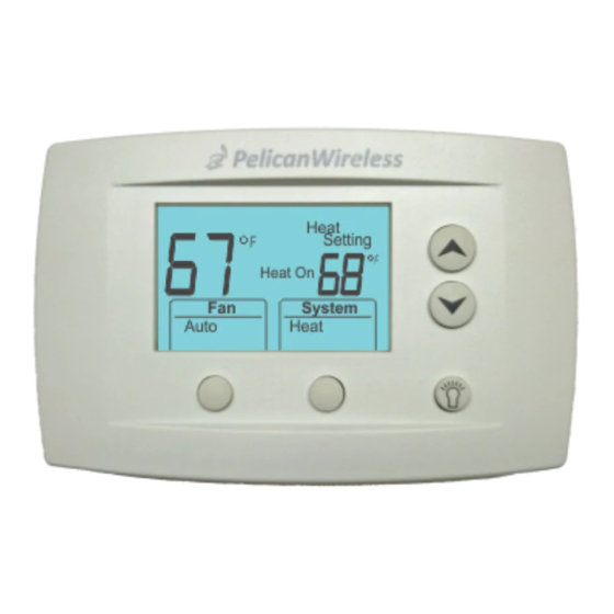
Programmable Thermostat
Before Removing the Old Thermostat!
Note the wire colors and letter designations of the existing thermostat to
assist in identifying the correct wiring connections to the TS200.
!
Failure to follow these instructions can damage the product or cause a hazardous
condition. Disconnect power during the installation of this product. All wiring must conform
to local codes and ordinances. We strongly recommend that any installation or servicing
be performed by a qualified technician. This thermostat is designed for use with 24VAC
systems only. For additional support contact Pelican Technical Support at 888-512-0490
or email support@pelicanwireless.com
WARNING
!
Thermostat Terminal Designations
Conventional Control
DATA
COMMON
24VAC (COOL)
24VAC (HEAT)
COOL STAGE 1
HEAT STAGE 1
FAN
HEAT STAGE 2
COOL STAGE 2
Internet
TS200
NEVER INSTALL THE PELICAN THERMOSTAT ENCLOSED IN METAL.
WIRELESS CANNOT COMMUNICATE THROUGH METAL.
D
C
R
Rc
Y
W
G
W2
Y2
Installation Guide
DATA
COMMON
24VAC
24VAC
COMPRESSOR STAGE 1
REVERSING VALVE (O/B)
FAN
AUXILIARY HEAT
COMPRESSOR STAGE 2
Heat Pump Control
!
D
C
R
Rc
Y
W
G
W2
Y2
Advertisement
Table of Contents

Related Manuals for Pelican TS200


Summary of Contents for Pelican TS200
-
Page 1: Installation Guide
Before Removing the Old Thermostat! Note the wire colors and letter designations of the existing thermostat to assist in identifying the correct wiring connections to the TS200. Failure to follow these instructions can damage the product or cause a hazardous condition. - Page 2 TS200 Mounting and Assembly Grasp front and back of thermostat and firmly pull apart. Mount thermostat rear cover to the wall. Remove old thermostat Old thermostat Pelican Y W G W Y Wireless Systems Option One: Wiring Module Model: WM500...
- Page 3 TS200 Mounting and Assembly Align three pin connector from thermostat front cover to three pin connector on rear cover. Push front cover onto rear cover until secure. Pelican Wilreless Systems Pelican Y W G W Y Wireless Systems LISTED ENERGY MGMT EQPT...
- Page 4 Conventional Wiring Guide 5 Wire, 24VAC Conventional 1 stage cooling with 1 stage heat Fan Circuit Heat Circuit Compressor Relay 24 VAC Power 24 VAC Common Use 18 gauge unshielded cable from thermostat to the equipment. R Rc Y W G W For a Two Transformer System –...
- Page 5 Conventional Wiring Guide 6 Wire, 24VAC Conventional 1 stage cooling with 2 stage heat 2nd Stage Heat Circuit Fan Circuit 1st Stage Heat Circuit Compressor Relay 24 VAC Power 24 VAC Common Use 18 gauge unshielded cable from thermostat to the equipment.
- Page 6 Conventional Wiring Guide 6 Wire, 24VAC Conventional 2 stage cooling with 1 stage heat 2nd Stage Compressor Fan Circuit 1st Stage Heat Circuit 1st Stage Compressor 24 VAC Power 24 VAC Common Use 18 gauge unshielded cable from thermostat to the equipment.
- Page 7 Conventional Wiring Guide 7 Wire, 24VAC Conventional 2 stage cooling with 2 stage heat 2nd Stage Compressor 2nd Stage Heat Circuit Fan Circuit 1st Stage Heat Circuit 1st Stage Compressor 24 VAC Power 24 VAC Common Use 18 gauge unshielded cable from thermostat to the equipment.
- Page 8 Conventional Wiring Guide 7 Wire, 24VAC Conventional 1 stage cooling, 2 stage heat, and 2 fan speeds High Fan Speed 2nd Stage Heat Circuit Low Fan Speed 1st Stage Heat Circuit Compressor Relay 24 VAC Power 24 VAC Common Use 18 gauge unshielded cable from thermostat to the equipment.
- Page 9 Heat Pump Wiring Guide 5 Wire, 24VAC Heat Pump 1 stage cooling with 1 stage heat Fan Circuit Reversing Valve Compressor Relay 24 VAC Power 24 VAC Common Use 18 gauge unshielded cable from thermostat to the equipment. Rc Y W G W (O/B)
- Page 10 Heat Pump Wiring Guide 6 Wire, 24VAC Heat Pump 2 stage cooling with 2 stage heat 2nd Compressor Relay Fan Circuit Reversing Valve 1st Compressor Relay 24 VAC Power 24 VAC Common Use 18 gauge unshielded cable from the thermostat to the equipment.
- Page 11 Heat Pump Wiring Guide 6 Wire, 24VAC Heat Pump 2 stage cooling, 1 stage heat and auxiliary/emergency heat Auxiliary/Emergency Heat Fan Circuit Reversing Valve 1st Compressor Relay 24 VAC Power 24 VAC Common Use 18 gauge unshielded cable from the thermostat to the equipment.
- Page 12 Heat Pump Wiring Guide 7 Wire, 24VAC Heat Pump 2 stage cooling, 2 stage heat and auxiliary/emergency heat 2nd Compressor Relay Auxiliary/Emergency Heat Fan Circuit Reversing Valve 1st Compressor Relay 24 VAC Power 24 VAC Common Use 18 gauge unshielded cable from the thermostat to the equipment.
- Page 13 Heat Pump Wiring Guide 7 Wire, 24VAC Heat Pump 1 stage cooling, auxiliary/emergency heat, and 2 stage fan High Speed Fan Auxiliary/Emergency Heat Low Speed Fan Reversing Valve Compressor Relay 24 VAC Power 24 VAC Common Use 18 gauge unshielded cable from the thermostat to the equipment.
- Page 14 Optional Three Wire Installation Some installations may have limited in-wall wire. In these cases, the TS200 can accommodate the use of only three wires and still provide control over the entire HVAC unit. To accomplish a three wire installation follow the steps outlined below: 1.
- Page 15 5. Use the existing in-wall 18 gauge unshielded wire to connect the R, C, D terminals from the WM500 to the matching R, C, D terminals at the thermostat WM500 INSTALLED INSIDE HVAC UNIT THE WIRING BELOW IS FOR A NOTE STANDARD FIVE (5) WIRE INSTALLATION.
-
Page 16: Thermostat Configuration
All configuration settings are made Online through the Pelican Web App. Each thermostat will automatically join the Pelican Web App and will be listed both as a notification and as a new thermostat under Admin. The thermostat is intially listed by it’s serial number.
Need help?
Do you have a question about the TS200 and is the answer not in the manual?
Questions and answers
How to delete schedule from thermostat