Advertisement
PELICAN
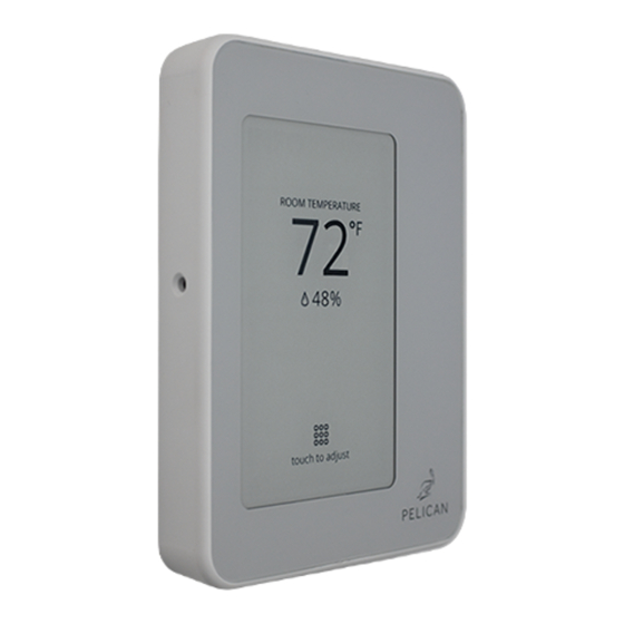
Model: TC2
Commercial Connected Thermostat
with Humidity
Installation Guide
!
Before you start
Review all instructions before starting to avoid discovering or creating any
issues during installation. This thermostat is designed to be installed on 24
VAC systems only.
This thermostat is designed to be installed by a licensed professional.
A Pelican Gateway must be used with this thermostat. The thermostat cannot
be configured or managed without the gateway. We recommend installing
the gateway prior to installing this product.
Installation location
NEVER INSTALL IN AN ENCLOSED METAL BOX OR ON A METAL SURFACE.
Install in a location where it can communicate with the Pelican wireless mesh
network.
Install 48" to 60" from the floor in the room where it will be maintaining the
temperature.
Install on an interior wall away from doors, filing cabinets, electrical
equipment, or other metal objects.
Advertisement
Table of Contents

Related Manuals for Pelican TC2


Summary of Contents for Pelican TC2
- Page 1 Installation location NEVER INSTALL IN AN ENCLOSED METAL BOX OR ON A METAL SURFACE. Install in a location where it can communicate with the Pelican wireless mesh network. Install 48" to 60" from the floor in the room where it will be maintaining the temperature.
-
Page 2: Turn Off Power
Pelican thermostat. Uninstall the old thermostat and set aside. Installing a Pelican thermostat in a new location This Pelican thermostat is designed to either mount flush on the wall or on a vertical 1-gang electrical box. -
Page 3: Electrical Box Installation
Install the thermostat back plate Use the included screws to attach the thermostat to the wall following one of the examples below: electrical box installation wall installation Drill two 3/16" holes (if using drywall Vertical electrical anchors). box. Install provided drywall anchors (if required). -
Page 4: Limited Wire Installation
Limited Wire Installation Some installations have limited wires Wiring Module between the thermostat and the HVAC equipment. The included Wiring Module can be used to control the HVAC equipment without having to run new or additional wires to the thermostat. This installation requires at least three (3) wires between the thermostat and the Wiring Module (unshielded wire is... - Page 5 Step 3: Connect Wiring Module to thermostat. Use the existing wires from the Wiring Module to where the thermostat is installed to connect the (R), (C), and (D) terminals from the Wiring Module to the matching (R), (C), and (D) terminals at the thermostat’s back plate. Wiring Module mounted at control board.
- Page 6 Switch on the power to the HVAC equipment the thermostat is wired to. If your Pelican thermostat does not power on, see page 17 for assistance. See page 18 for instructions on setting the thermostat for Conventional or Heat there are three (3) alignment Pump control.
-
Page 7: Wiring Guides
For zone damper control, see separate installation guide Zone Damper Control. For installations that are outside of this installation guide, STOP INSTALLING THE THERMOSTAT, and contact Pelican Sales Engineering Support for further assistance at 888.512.0490. 24 VAC Terminal Block Designations... - Page 8 Conventional Heating and Cooling Systems (Up to 2 stages each) 2nd Stage Cooling 2nd Stage Heating Supply Fan 1st Stage Heating 1st Stage Cooling 24 VAC Common 24 VAC Power Notes can be found on page 17.
- Page 9 Conventional Heating and Cooling Systems (Up to 1 stages cool, 2 stages heat, and 2 speed fan) High Speed Supply Fan 2nd Stage Heating Low Speed Supply Fan 1st Stage Heating 1st Stage Cooling 24 VAC Common 24 VAC Power Notes can be found on page 17.
- Page 10 Heat Pump Systems (Up to 2 stages each and Auxiliary/Emergency Heat) 2nd Stage Compressor AUX/Emergency Heat Supply Fan Reversing Valve 1st Stage Compressor 24 VAC Common 24 VAC Power Notes can be found on page 17.
- Page 11 Heat Pump Systems (Up to 1 stages each, 2 speed fan, and Auxiliary/Emergency Heat) High Speed Supply Fan AUX/Emergency Heat Low Speed Supply Fan Reversing Valve 1st Stage Compressor 24 VAC Common 24 VAC Power Notes can be found on page 17.
- Page 12 Two-Pipe Fan Coils* (Power-open/spring-return or floating water valve) Water Valve Close AUX/Emergency Heat Supply Fan (Unused) Water Valve Open 24 VAC Common 24 VAC Power Notes can be found on page 17. *Contact Pelican Technical Support for thermostat configuration assistance.
- Page 13 (Power-open/spring-return water valve and 2 speed fan) High Speed Supply Fan AUX/Emergency Heat Low Speed Supply Fan (Unused) Water Valve Open 24 VAC Common 24 VAC Power Notes can be found on page 17. *Contact Pelican Technical Support for thermostat configuration assistance.
- Page 14 (Power-open/spring-return or floating water valve*) Chilled Water Valve Close Hot Water/Steam Valve Close Supply Fan Hot Water/Steam Valve Open Chilled Water Valve Open 24 VAC Common 24 VAC Power Notes can be found on page 17. *Contact Pelican Technical Support for thermostat configuration assistance.
- Page 15 Four-Pipe Fan Coils (Power-open/spring-return water valves and 2 speed fan) High Speed Supply Fan AUX/Emergency Heat Low Speed Supply Fan Hot Water/Steam Valve Open Chilled Water Valve Open 24 VAC Common 24 VAC Power Notes can be found on page 17.
- Page 16 Humidity Control (Humidify and/or Dehumidify) Dehumidifier/Hot Gas Bypass Enable Humidifier Enable Notes can be found on page 17.
-
Page 17: Troubleshooting
If the thermostat still does not power on, contact Pelican technical support for further assistance at 888.512.0490. If the Pelican thermostat does not show up on the Pelican App, check the following: 1. Check the thermostat upper right hand corner. - Page 18 • Verify your Pelican thermostat is not in a metal enclosure and that there are no metal structures/objects surrounding it. Wireless can NOT communicate through metal. 2. If you see this symbol then the thermostat is connected to your Pelican Wireless Mesh Network, but your Pelican Gateway is unable to reach the Internet.
- Page 19 To access the configuration page, select Touch to adjust and then press the icon in the upper right hand corner of the screen. Under Configuration, you will see the current control setting (default configuration is Conventional). To change the configuration, press the change button to the right of Configuration. Then touch Conventional, Heat Pump (O), or Heat Pump (B) and press Save at the bottom of the screen to set the new configuration.
- Page 20 PELICAN Website: www.pelicanwireless.com Pelican Wireless Systems. All Rights Reserved. Phone: 888.512.0490 TC2 37-2201 REV 03...
Need help?
Do you have a question about the TC2 and is the answer not in the manual?
Questions and answers