Table of Contents
Advertisement
Advertisement
Chapters
Table of Contents
Troubleshooting

Related Manuals for Tennant 6200E


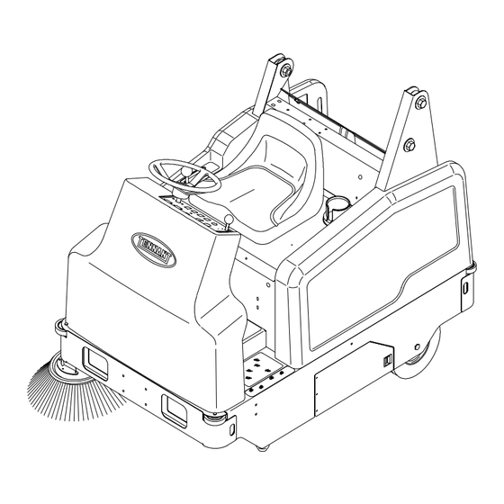
Summary of Contents for Tennant 6200E
- Page 1 6200E Service Manual 330415 Rev. 01 (12- -01)
- Page 2 Sweeping: V--belt replacement, brush replacement, bearing replacement, skirt/seal repair/replacement, and sweeping troubleshooting. Electrical: Battery maintenance and replacement, electrical schematics, and electrical troubleshooting. Hydraulics: Cylinder replacement/repair, pump replacement/repair, hydraulic schematic, and hydraulic troubleshooting. Manual Number -- 330415 Revision: 01 Published: 12--01 Copyright E 1999, 2001 TENNANT, Printed in U.S.A.
-
Page 3: Table Of Contents
... 1--14 HYDRAULIC O--RING FITTING TORQUE CHART ....1--14 MACHINE TROUBLESHOOTING ..1--15 6200E 330415 (12- -01) - Page 4 GENERAL INFORMATION 6200E 330415 (6- -99)
-
Page 5: Safety Precautions
- - Disconnect battery connections before equipment: working on machine. - - Avoid contact with battery acid. FOR SAFETY: - - Use Tennant supplied or equivalent replacement parts. 1. Do not operate machine: - - Unless trained and authorized. 7. When loading/unloading machine... - Page 6 FOR SAFETY LABEL - - LOCATED ON THE SIDE OF THE OPERATOR COMPARTMENT. HOPPER LIFT ARMS LABEL - - LOCATED ON BOTH LIFT ARMS. HOPPER SUPPORT LABEL - - LOCATED ON INSIDE METAL PANEL ON BOTH SIDES OF MACHINE. 6200E 330415 (6- -99)
-
Page 7: Specifications
Minimum aisle turn 2095 mm (82.5 in) Minimum turning radius, left 1400 mm (55 in) Minimum turning radius, right 1400 mm (55 in) Maximum rated incline with empty hopper 10_/18% Maximum rated incline with full hopper 6_/11% 6200E 330415 (12- -01) -
Page 8: Power Type
Parking brake Utilizes service brakes, cable actuated TIRES Location Type Size Front (1) Solid 102 x 305 mm (4 in x12 in OD) Rear (2) Solid 76 x 305 mm (3 in x 12 in OD) 6200E 330415 (12- -01) -
Page 9: Machine Dimensions
GENERAL INFORMATION 1783 mm (70 in) 1397 mm (55 in) 1067 mm (42 in) TOP VIEW 2035 mm (80 in) 1435 mm (56.5 in) SIDE VIEW FRONT VIEW 352945 MACHINE DIMENSIONS 6200E 330415 (12- -01) -
Page 10: Maintenance
50 Hours Main brush Rotate end-for-end QuickMoptbroom (Option) Rotate or wash sweep heads Batteries Check electrolyte level 6 (3) Vacuum wand bag (Option) Check or change vacuum bag Vacuum wand fan (Option) Check for damage or wear 6200E 330415 (12- -01) - Page 11 Tennant or approved hydraulic fluid . . . Special lubricant, Lubriplate EMB grease (TENNANT part no. 01433--1) NOTE: Also check procedures indicated (H) after the first 50 hours of operation. NOTE: More frequent intervals may be required in extremely dusty conditions.
-
Page 12: Pushing, Towing, And Transporting The Machine
FOR SAFETY: When loading machine onto truck or trailer, use winch. Do not drive the machine onto the truck or trailer unless the loading surface is horizontal AND is 380 mm (15 in) or less from the ground. 6200E 330415 (12- -01) 1-10... - Page 13 FOR SAFETY: When unloading machine off truck or trailer, use winch. Do not drive the machine off the truck or trailer unless the loading surface is horizontal AND 380 mm (15 in) or less from the ground. 6200E 330415 (12- -01) 1-11...
-
Page 14: Machine Jacking
Block machine up with jack stands. STORING MACHINE Before storing the machine for an extended time, the machine needs to be serviced to lessen the chance of rust, sludge, and other undesirable deposits from forming. 6200E 330415 (12- -01) 1-12... -
Page 15: Hardware Information
(291--380) (424--552) Locktite 515 sealant -- gasket forming 1.00 in 500--650 757--984 material. TENNANT Part No. 75567,15 oz (678--881) (1026--1334) (440 ml) cartridge. NOTE: Decrease torque by 20% when using a Locktite 242 blue -- medium strength thread thread lubricant. -
Page 16: Hydraulic Fitting Information
(81 Nm) (122 Nm) 0.62 0.88--14 40 ft lb (54 Nm) NOTE: Do not use sealant on o- -ring threads. 0.75 1.12--12 70 ft lb (95 Nm) 1.31--12 90 ft lb (122 Nm) *Aluminum bodied components 6200E 330415 (6- -99) 1-14... -
Page 17: Machine Troubleshooting
Large debris trap damaged Repair or replace large debris trap Hopper dust filter clogged Shake and/or clean or replace dust filter Hopper door partially or Open the hopper door completely closed Recirculation flap damaged Replace flap 6200E 330415 (6- -99) 1-15... - Page 18 GENERAL INFORMATION 6200E 330415 (12- -01) 1-16...
- Page 19 2--19 TO REPLACE DRIVE ASSEMBLY CASTER BEARING AND THRUST WASHERS ..2--21 TO REPLACE DRIVE ASSEMBLY PIVOT CONE BEARING ..2--26 6200E 330415 (6- -99)
- Page 20 CHASSIS 6200E 330415 (6- -99)
-
Page 21: Introduction
CHASSIS INTRODUCTION This section includes information on the main chassis related components, for example; the seat, steering, front drive assembly, brakes and tires. 6200E 330415 (6- -99) -
Page 22: Operator Seat
OPERATOR SAFETY SWITCH The operator seat has a safety switch that stops the machine from propelling unless the operator is sitting in the operator’s seat. 6200E 330415 (6- -99) -
Page 23: Static Drag Chain
The parking brake is located on the front wheel assembly. It is actuated with a smaller toe lever on the top of the foot brake pedal in the operators compartment. It is deactivated by simply pushing on the foot brake pedal. 6200E 330415 (6- -99) -
Page 24: To Adjust Service Brakes
5. Move the cable away from the brake lever far enough to remove the slack in the pedal movement. 6. Re--tighten the two jam nuts firmly. Operate the machine and check the brake pedal for a shorter stroke. 6200E 330415 (6- -99) -
Page 25: To Adjust Parking Brake
5. Move the cable away from the brake lever far enough to remove the slack in the pedal movement. 6. Re--tighten the two jam nuts firmly. Operate the machine and check the brake pedal for a shorter stroke. 6200E 330415 (6- -99) -
Page 26: To Replace Drive Assembly Brake Shoes
4. Remove the four hex screws holding the outer plate, motor, and planetary gear box to the main drive assembly. 5. Pull the planetary gear box, outer plate, and motor out of the drive wheel and away from the drive assembly. 6200E 330415 (6- -99) - Page 27 Care must be used when spreading the spring for removal or installation. 12. Install the new brake shoes on the drive assembly in the same orientation as the old ones were removed. 13. Reinstall the ”C” spring on the new brake shoes. 6200E 330415 (6- -99)
- Page 28 16. Install the lock bolt in the end of the hex sleeve. Tighten the lock bolt to 200 Nm (150 ft lb) while holding the hex sleeve from turning. 17. Reinstall the hub cap in the drive assembly. 2-10 6200E 330415 (6- -99)
- Page 29 22. Reconnect the electrical cables to the drive motor. 23. Remove the jack stands and lower the machine. 24. Reconnect the battery cables. 25. Drive the machine and check the brakes for proper operation. Adjust if necessary. 2-11 6200E 330415 (6- -99)
-
Page 30: Rear Tires And Wheels
CHASSIS REAR TIRES AND WHEELS The rear tires on the model 6200E are semi--pneumatic. The rear tire and wheel assemblies are idler wheels only, they have no braking capabilities. TO REMOVE REAR TIRE FOR SAFETY: Before Leaving Or Servicing Machine; Stop On Level Surface, Set Parking Brake. -
Page 31: To Install Rear Tire
3. Install the washer and nut on the axle. Tighten to 68 -- 81 Nm (50 -- 60 ft lb). 4. Remove the jack stands and lower the machine. 5. Drive the machine and check for proper operation. 2-13 6200E 330415 (6- -99) -
Page 32: To Replace Rear Wheel Bearings
Remove the bearing housing. 3. Use a press to remove the wheel bearings from the housing. 4. Press the new wheel bearings into the housing. Press the bearing in until the flange is seated on the housing. 2-14 6200E 330415 (6- -99) - Page 33 58 -- 76 Nm (43 -- 56 ft lb). NOTE: The lug nuts must face the outside of the machine. 6. Reinstall the rear wheel assembly in the machine. See TO INSTALL REAR TIRE instructions. 2-15 6200E 330415 (6- -99)
-
Page 34: Front Tire And Wheel, And Wheel Drive Support
FRONT WHEEL SUPPORT CASTER BEARING ASSEMBLY The front wheel support caster bearing is located between the bottom swivel plate and the upper swivel plate weldment. The bearing is a flat needle bearing style. 2-16 6200E 330415 (6- -99) -
Page 35: To Remove Front Drive Assembly
4. Go in operators compartment and loosen the lower steering shaft mount screws. 5. Pull the mount back to give the steering chain slack. Locate and remove the master link and steering chain. 2-17 6200E 330415 (6- -99) - Page 36 9. Go to the operators compartment and locate the 4 button head screws holding the drive assembly to the floor plate. Remove the 4 screws while supporting the drive assembly. 10. Remove the drive assembly from the machine. 2-18 6200E 330415 (6- -99)
-
Page 37: To Install Front Drive Assembly
7. Reinstall the steering chain and master link. Adjust the steering chain. See TO ADJUST STEERING CHAIN instructions. 8. Reinstall the brake cable on the wheel support. Tighten the jam nut on the brake cable where it attaches to the wheel support. 2-19 6200E 330415 (6- -99) - Page 38 13. Remove the jack stands and lower the machine. 14. Reconnect the battery cables. 15. Operate the machine and check for proper operation. Check the brakes for proper operation. Adjust if necessary. See TO ADJUST SERVICE BRAKES instructions. 2-20 6200E 330415 (6- -99)
-
Page 39: To Replace Drive Assembly Caster Bearing And Thrust Washers
2. Remove the four hex screws holding the outer plate, motor, and planetary gear box to the main drive assembly. 3. Pull the planetary gear box, outer plate, and motor out of the drive wheel and away from the drive assembly. 2-21 6200E 330415 (6- -99) - Page 40 6. Remove the cotter pin and castle nut from the upper swivel plate weldment. 7. Remove the flat washer and cone bearing from the bottom swivel plate. 8. Lift the bottom swivel plate off the upper swivel plate weldment. 2-22 6200E 330415 (6- -99)
- Page 41 Make sure the grease seal is in place on the upper swivel plate weldment. 14. Reinstall the bearing cone and flat washer on the bottom swivel plate. Make sure the bearing cone is greased. 2-23 6200E 330415 (6- -99)
- Page 42 18. Install the planetary gear box, outer plate, and motor assembly into the wheel assembly and onto the pins of the drive assembly. 19. Install the 4 hex screws and washers. Tighten to 18 -- 24 Nm (15 -- 20 ft lb). 2-24 6200E 330415 (6- -99)
- Page 43 20. Reinstall the drive assembly in the machine. See TO INSTALL FRONT DRIVE ASSEMBLY instructions. 21. Operate the machine and check for smooth steering operation. Check the brakes for proper operation. Adjust if necessary. See TO ADJUST SERVICE BRAKES instructions. 2-25 6200E 330415 (6- -99)
-
Page 44: To Replace Drive Assembly Pivot Cone Bearing
2. Remove the four hex screws holding the outer plate, motor, and planetary gear box to the main drive assembly. 3. Pull the planetary gear box, outer plate, and motor out of the drive wheel and away from the drive assembly. 2-26 6200E 330415 (6- -99) - Page 45 9. Reinstall the castle nut and tighten to 200 Nm (150 ft lbs). Then tighten to the next nearest hole and install the cotter pin. 10. Reinstall the sprocket on the pivot assembly. 2-27 6200E 330415 (6- -99)
- Page 46 14. Reinstall the drive assembly in the machine. See TO INSTALL FRONT DRIVE ASSEMBLY instructions. 15. Operate the machine and check for smooth steering operation. Check the brakes for proper operation. Adjust if necessary. See TO ADJUST SERVICE BRAKES instructions. 2-28 6200E 330415 (6- -99)
-
Page 47: Planetary Gear Box
CHASSIS PLANETARY GEAR BOX The model 6200E front drive system includes a self contained planetary gearbox. The electric drive motor provides power to the planetary gearbox which, through a gear reduction, spins the front tire. TO REMOVE PLANETARY GEAR BOX FOR SAFETY: Before Leaving Or Servicing Machine;... - Page 48 6. Remove the 6 socket screws holding the outer plate to the planetary gear box. Remove the outer plate. 7. Pull the old planetary gear box out of the drive wheel. Remove the old planetary gear box from the machine. 2-30 6200E 330415 (6- -99)
-
Page 49: To Install Planetary Gear Box
Make sure to line up the splines on the motor shaft with the splines of the planetary gear box. Tighten the 4 hex screws to 18 -- 24 Nm (15 -- 20 ft lb). 2-31 6200E 330415 (6- -99) - Page 50 4. Reconnect the electrical cables to the drive motor. 5. Remove the jack stands and lower the machine. 6. Reconnect the battery cables. 7. Operate the machine and check the new gearbox for proper operation. 2-32 6200E 330415 (6- -99)
-
Page 51: To Replace Front Tire And Wheel Assembly
6. Go to the other side of the drive assembly and remove the hub cap. This will expose the outer bearing, hex sleeve, and lock bolt. 2-33 6200E 330415 (6- -99) - Page 52 10. Install the inner bearing on the new tire/wheel assembly. 11. Reinstall the new tire/wheel assembly in the drive assembly. Make sure the inner and outer wheel bearings are completely greased when re--assembling. 2-34 6200E 330415 (6- -99)
- Page 53 14. Reinstall the hub cap in the drive assembly. 15. Go to the other side of the drive assembly. Install the planetary gear box, outer plate, and motor assembly into the wheel assembly and onto the pins of the drive assembly. 2-35 6200E 330415 (6- -99)
- Page 54 Tighten to 18 -- 24 Nm (15 -- 20 ft lb). 17. Reconnect the electrical cables to the drive motor. 18. Remove the jack stands and lower the machine. 19. Reconnect the battery cables. 20. Drive the machine and check for proper operation. 2-36 6200E 330415 (6- -99)
-
Page 55: To Replace Front Drive Assembly Outer Wheel Bearing
6. Use a press to remove the old outer bearing cone from the hex sleeve. Install a new outer bearing on the hex sleeve or replace the bearing and sleeve assembly. Apply grease to the new bearing. 2-37 6200E 330415 (6- -99) - Page 56 9. Reinstall the hub cap in the drive assembly. 10. Remove the jack stands and lower the machine. 11. Reconnect the battery cables. 12. Drive the machine and check for proper operation. 2-38 6200E 330415 (6- -99)
-
Page 57: To Replace Front Drive Assembly Inner Wheel Bearing
6. Go to the other side of the drive assembly and remove the hub cap. This will expose the outer bearing, hex sleeve, and lock bolt. 2-39 6200E 330415 (6- -99) - Page 58 10. Press a new inner wheel bearing on the wheel shaft. Apply grease to the new bearing. 11. Reinstall the tire/wheel assembly in the drive assembly. Make sure the inner and outer wheel bearings are completely greased when re--assembling. 2-40 6200E 330415 (6- -99)
- Page 59 14. Reinstall the hub cap in the drive assembly. 15. Go to the other side of the drive assembly. Install the planetary gear box, outer plate, and motor assembly into the wheel assembly and onto the pins of the drive assembly. 2-41 6200E 330415 (6- -99)
- Page 60 Tighten to 18 -- 24 Nm (15 -- 20 ft lb). 17. Reconnect the electrical cables to the drive motor. 18. Remove the jack stands and lower the machine. 19. Reconnect the battery cables. 20. Drive the machine and check for proper operation. 2-42 6200E 330415 (6- -99)
-
Page 61: Steering
CHASSIS STEERING The steering on the model 6200E is controlled with two sprockets and one chain. A large diameter sprocket is mounted on the top of the front drive assembly and a small diameter sprocket is mounted on the bottom of the steering shaft. -
Page 62: To Replace Steering Chain
7. Route the new chain around both steering sprockets. Install the master link. 8. Remove the jack stands and lower the machine. 9. Operate the machine and check the steering for proper operation. 2-44 6200E 330415 (6- -99) -
Page 63: To Replace Large Steering Sprocket
3. Remove the old sprocket from the pivot assembly. 4. Install the new sprocket on the pivot assembly. NOTE: Make sure the roll pin in the top of the drive assembly lines up with the hole in the sprocket. 2-45 6200E 330415 (6- -99) - Page 64 68 -- 81 Nm (50 -- 60 ft lb). 6. Reinstall the drive assembly in the machine. See TO INSTALL FRONT DRIVE ASSEMBLY instructions. 7. Operate the machine and check for smooth steering operation. 2-46 6200E 330415 (6- -99)
-
Page 65: To Replace Small Steering Sprocket
4. Go under the machine and locate the steering chain. 5. Rotate the steering wheel until the master link on the chain is accessible. 6. Remove the chain master link. Remove the steering chain from both sprockets. 2-47 6200E 330415 (6- -99) - Page 66 Install the master link. 10. Adjust the steering chain. See TO ADJUST STEERING CHAIN instructions. 11. Remove the jack stands and lower the machine. 12. Operate the machine and check the steering for proper operation. 2-48 6200E 330415 (6- -99)
-
Page 67: To Replace Steering Housing Bearings
4. Pull the steering wheel and long steering shaft up and out of the top of the steering U--joint. 5. Remove the two hex screws holding the steering bearing housing to the machine frame. Push the bearing housing back in the slots. 2-49 6200E 330415 (6- -99) - Page 68 8. Remove the steering housing from the machine. 9. Loosen the two set screws holding the U--joint to the top of the short steering shaft. Remove and retain the U--joint and square key. 2-50 6200E 330415 (6- -99)
- Page 69 14. Reinstall the small steering sprocket and woodruff key on the bottom of the steering housing. Tighten the set screws tight. 15. Reinstall the U--joint and square key on the top of the steering housing. Tighten the set screws tight. 2-51 6200E 330415 (6- -99)
- Page 70 Tighten the two hex screws to 37 -- 48 Nm (26 -- 34 ft lb). 21. Remove the jack stands and lower the machine to the floor. Operate the machine and check the steering chain for proper operation. 2-52 6200E 330415 (6- -99)
-
Page 71: To Replace Steering U--Joint
U--joint. 4. Loosen the two set screws holding the U--joint to the top of the short steering shaft. Remove and discard the U--joint and square key. 2-53 6200E 330415 (6- -99) - Page 72 6. Position the long steering shaft and steering wheel into the top of the steering U--joint. Tighten the set screws tight. 7. Operate the machine and check the steering U--joint for proper operation. 2-54 6200E 330415 (6- -99)
- Page 73 ..... 3-40 TO REPLACE VACUUM FAN IMPELLER BEARINGS ..3-45 MACHINE TROUBLESHOOTING ..3-48 6200E 330415 (12- -01)
- Page 74 SWEEPING 6200E 330415 (6- -99)
-
Page 75: Introduction
SWEEPING INTRODUCTION This section includes information on the sweeping operation of the model 6200E. The side brush sweeps debris in front of the machine and the main brush sweeps the debris into the hopper. The vacuum fan pulls air from the hopper and through the dust filter. -
Page 76: Debris Hopper
The lift cylinder is provided hydraulic flow from a electro/hydraulic unit. The electro/hydraulic unit is activated with a dash mounted switch. The hopper is held in the raised position with a prop arm. 6200E 330415 (6- -99) -
Page 77: Hopper Dust Filter
Rinse the dust filter until it is clean. Air dry the wet dust filter; do not use compressed air to dry a wet filter. NOTE: Be sure the dust filter is completely dry before reinstalling it in the machine. 6200E 330415 (6- -99) -
Page 78: To Replace Hopper Dust Filter
Do not unplug the connections from the shaking mechanism. Do not pull on the wires. Damage could occur to the wires or the shaking mechanism. 4. Lift dust filter assembly out of hopper. 6200E 330415 (12- -01) - Page 79 6. Lift the VCSt system filter shaker off of the filter. 7. Clean or discard the Instant Accesst filter as required. 8. Replace the VCSt system filter shaker. Use care to insert the shaking pin into the filter comb correctly. 6200E 330415 (6- -99)
- Page 80 The gap should be the same width as the tab. If it is not, loosen the mounting screws, adjust the gap by repositioning the shaker solenoid, then retighten the screws. 12. Return the filter back to the machine. 6200E 330415 (12- -01)
- Page 81 SWEEPING 13. Reconnect the main harness to the shaker mechanism. 14. Check the dust filter seals. 15. Replace hopper cover and secure with latches. 6200E 330415 (12- -01)
-
Page 82: Main Brush
1. Stop the machine, set the parking brake and turn the machine power off. 2. Open the left side main brush access door. 3. Loosen the idler arm mounting knob and three other side skirt mounting knobs. Remove the brush idler arm assembly. 3-10 6200E 330415 (6- -99) - Page 83 8. Slide the main brush idler arm plug onto the main brush. 9. Secure the idler arm on the bolts. Hand tighten the mounting knobs. 10. Close the main brush access door. 6200E 330415 (6- -99) 3-11...
-
Page 84: Checking And Adjusting Main Brush Pattern
6. Observe the width of the brush pattern. The proper brush pattern width is 50 to 75 mm (2 to 3 in). The brush taper is factory set and should not need adjustment unless parts of the brush system have been replaced. 3-12 6200E 330415 (6- -99) - Page 85 B. Allow the brush to operate and float into position for approximately 30 seconds. C. Tighten the adjustment bolt and idler arm securing knob. D. Check the main brush pattern and readjust as necessary. 6200E 330415 (12- -01) 3-13...
-
Page 86: Main Brush Belt
2. Locate the main brush drive belt idler pulley between the small motor drive pulley and the larger brush pulley. 3. Loosen the hex nut in the center of the idler pulley. 4. Push the idler pulley back in the slot. 3-14 6200E 330415 (12- -01) - Page 87 Tighten the hex nut to 18 -- 24 Nm (15 -- 20 ft lb). 8. Reinstall the right hand side brush door. 9. Operate the machine and check the main brush for proper operation. 6200E 330415 (6- -99) 3-15...
-
Page 88: To Replace Main Brush Idler Plug Bearing
See TO REPLACE MAIN BRUSH instructions in this sections. 3. Remove the idler arm from the brush lift plate. 4. Remove the hex screw, nut, and washer holding the idler plug assembly to the brush lift plate. 3-16 6200E 330415 (6- -99) - Page 89 8. Position the new ball bearing into the idler plug. 9. Reinstall the bearing retainer plate on the idler plug. Reinstall the four screws and tighten to 8 -- 10 Nm (6 -- 7 ft lb). 6200E 330415 (6- -99) 3-17...
- Page 90 12. Reinstall the main brush idler mount plate. See TO REPLACE MAIN BRUSH instructions in this sections. 13. Close the left hand side brush door. 14. Operate the machine and check the main brush for proper operation. 3-18 6200E 330415 (6- -99)
-
Page 91: To Replace Main Brush Drive Plug Shaft Bearings
4. Remove the main brush. See TO REPLACE MAIN BRUSH instructions in this sections. 5. Remove the main brush drive belt. See TO REPLACE MAIN BRUSH DRIVE BELT instructions in this section. 6200E 330415 (6- -99) 3-19... - Page 92 8. Hold the main brush drive plug from turning. Remove the large nut from the center of the drive plug. NOTE: This is a left hand thread nut. 9. Remove the main brush idler plug assembly from the main brush shaft. 3-20 6200E 330415 (6- -99)
- Page 93 17. Install the new bearing and main brush shaft assembly into the main brush bearing housing. Install the nut onto the inside of the main brush shaft. Use a hammer to lightly tap the bearing and shaft into the housing. 6200E 330415 (6- -99) 3-21...
- Page 94 Tighten to 52 -- 67 Nm (39 -- 51 ft lb). 20. Reinstall the main brush drive belt. See TO REPLACE MAIN BRUSH DRIVE BELT instructions in this section. 21. Reinstall the main brush. See TO REPLACE MAIN BRUSH instructions in this sections. 3-22 6200E 330415 (6- -99)
- Page 95 22. Reinstall the right hand brush door and close the left hand brush door. 23. Remove the jack stands and lower the machine. 24. Operate the machine and check the main brush for proper operation. 6200E 330415 (6- -99) 3-23...
-
Page 96: To Replace Main Brush Drive Belt Idler Pulley
3. Loosen the hex nut in the center of the idler pulley. 4. Push the idler pulley back in the slot. 5. Remove the main brush drive belt from the two remaining pulleys. 3-24 6200E 330415 (6- -99) - Page 97 Tighten the pulley nut to 18 -- 24 Nm (15 -- 20 ft lb). 10. Reinstall the right hand side brush door. 11. Operate the machine and check the main brush for proper operation. 6200E 330415 (6- -99) 3-25...
-
Page 98: Side Brush
FOR SAFETY: Before Leaving Or Servicing Machine; Stop On Level Surface, Set Parking Brake. 2. Remove the side brush retaining pin from the side brush drive shaft by pulling the pin keeper off over the end of the pin. 3-26 6200E 330415 (12- -01) - Page 99 Move the pulley mount bracket up or down to achieve the proper side brush pattern. Retighten the hex screw. 6200E 330415 (6- -99) 3-27...
-
Page 100: Side Brush Guard
SIDE BRUSH PIVOT The side brush pivot should be checked for excessive movement after every 200 hours of operation. Torque the front and rear compression springs to reduce excessive movement. 3-28 6200E 330415 (12- -01) -
Page 101: To Replace Side Brush Lift Cable
3. Go to the operators compartment. Remove the two cable pulleys, sleeves, and cable clips from the side brush lift cable. NOTE: Note the orientation of the cable clips for proper re- -assembly. 6200E 330415 (6- -99) 3-29... - Page 102 6. Route the new side brush lift cable in the machine. 7. Reinstall the three cable pulleys, sleeves, and cable clips. Make sure the cable clips are in the correct orientation. Tighten the hardware to 18 -- 24 Nm (15 -- 20 ft lb). 3-30 6200E 330415 (6- -99)
- Page 103 Hand tighten the hex nut. Cable should pivot on the hardware. 9. Connect the side brush lift cable to the lift handle. 10. Raise the side brush. Check the new cable for smooth operation. 6200E 330415 (6- -99) 3-31...
-
Page 104: Skirts And Seals
SIDE SKIRTS The side skirts are located on both sides of the main brush compartment. The skirts should clear the floor up to 5 mm. 3-32 6200E 330415 (6- -99) -
Page 105: Large Debris Trap Skirt
The hopper rests against the seals when the hopper is in the closed position. Check the seals for wear or damage after every 100 hours of operation. WARNING: Raised hopper may fall. Engage hopper support bar. 6200E 330415 (12- -01) 3-33... -
Page 106: Hopper Door Seal
Raising the front skirt will allow large debris to enter the main brush area and be deposited into the hopper. Check the seal for wear or damage after every 100 hours of operation. 3-34 6200E 330415 (12- -01) -
Page 107: Vacuum Fan
100 hours of operation. The correct tension is when the belt deflects 13.0 mm (0.50 in) from a force of 17 kg (38 lb) at belt midpoint. WARNING: Moving belt and fan. Keep away. 6200E 330415 (12- -01) 3-35... -
Page 108: To Replace Vacuum Fan Drive Belt
2. Remove the right hand side brush door. 3. Loosen the five hex screws holding the vacuum fan housing to the machine frame. 4. Push the vacuum fan assembly forward in the slots to loosen the vacuum fan V--belt. 3-36 6200E 330415 (6- -99) - Page 109 Tighten the five mounts screws hand tight. The correct tension is when the belt deflects 13.0 mm (0.50 in) from a force of 17 kg (38 lb) at belt midpoint. 9. Reinstall the V--belt cover. Tighten the two screws hand tight. 6200E 330415 (12- -01) 3-37...
- Page 110 SWEEPING 10. Reinstall the right hand machine cover. 11. Reinstall the right hand brush door. 12. Operate the machine. Check the vacuum fan for proper operation. 3-38 6200E 330415 (6- -99)
-
Page 111: To Adjust Vacuum Fan Drive Belt Tension
13.0 mm (0.50 in) from a force of 17 kg (38 lb) at belt midpoint. 4. Tighten the four vacuum housing mount screws hand tight. 5. Reinstall the right hand machine cover. 6. Operate the machine. Check the vacuum fan for proper operation. 6200E 330415 (12- -01) 3-39... -
Page 112: To Replace Vacuum Fan Impeller
V--belt. 5. Remove the two hex screws holding the cover over the V--belt pulley. Remove the cover. 6. Remove the vacuum fan V--belt from the vacuum fan sheave. 3-40 6200E 330415 (6- -99) - Page 113 NOTE: Make sure to retain the five steel sleeves. 11. Remove the nyloc nut holding the vacuum fan impeller to the fan shaft. Pull the impeller off the shaft. NOTE: Make sure to retain the square key. 6200E 330415 (6- -99) 3-41...
- Page 114 Reinstall the five hex screws and nuts. Make sure to install the two steel sleeves on the bottom two hex screws. Leave the hardware loose for now. 16. Install the vacuum fan V--belt over the fan sheave. 3-42 6200E 330415 (6- -99)
- Page 115 (.90 to .95 lb) at belt midpoint. 18. Tighten the five mounts screws hand tight. 19. Reinstall the V--belt cover. Tighten the two screws hand tight. 20. Connect the wires to the Thermo Sentryt. 21. Reinstall the right hand machine cover. 6200E 330415 (6- -99) 3-43...
- Page 116 SWEEPING 22. Start the machine, raise the hopper, disengage the prop arm. Lower the hopper. 23. Operate the machine. Check the vacuum fan for proper operation. 3-44 6200E 330415 (6- -99)
-
Page 117: To Replace Vacuum Fan Impeller Bearings
2. Loosen the two set screws holding the V--belt pulley to the fan shaft. Remove the pulley. 3. Remove the four hex screws holding the vacuum fan bearing assembly to the bearing plate. Remove the bearing assembly. 6200E 330415 (6- -99) 3-45... - Page 118 Tighten to 8 -- 10 Nm (6 -- 8 ft lb). 7. Reinstall the V--belt pulley on the short end of the fan shaft. The recessed side of the pulley goes to the inside. Hand tighten the set screws tight. 3-46 6200E 330415 (6- -99)
- Page 119 Make sure to reinstall the square key on the fan shaft. 9. See TO REMOVE VACUUM FAN IMPELLER instructions to install the vacuum fan impeller and the vacuum fan assembly into the machine. 6200E 330415 (6- -99) 3-47...
-
Page 120: Machine Troubleshooting
Large debris trap damaged Repair or replace large debris trap Hopper dust filter clogged Shake and/or clean or replace dust filter Hopper door partially or Open the hopper door completely closed Recirculation flap damaged Replace flap 3-48 6200E 330415 (6- -99) - Page 121 ....4-78 FILTER SHAKER ..... 4-81 6200E 330415 (12- -01)
- Page 122 ELECTRICAL 6200E 330415 (6- -99)
-
Page 123: Introduction
ELECTRICAL INTRODUCTION The 6200E electrical system consists of the batteries, instrument panel, drive motor, switches, relays, and circuit breakers. 6200E 330415 (5- -99) -
Page 124: Electrical System
ELECTRICAL ELECTRICAL SYSTEM The model 6200E is a battery powered, all electric machine. The batteries are used to power the front drive motor, vacuum fan motor, main brush motor, side brush motor, and the filter shaker. BATTERIES The batteries are unique in that they hold their power for long periods of time. -
Page 125: To Charge Batteries
FOR SAFETY: Before leaving or servicing machine, stop on level surface, set parking brake, turn off machine, and remove key. 3. Open the seat support. 4. Check the water level in all the battery cells. 08247 6200E 330415 (12- -01) - Page 126 NOTE: If the red “ABNORMAL CYCLE” lamp lights when the batteries are plugged into the TENNANT charger, this indicates that something is wrong with the battery. The charger can not charge the battery when this happens. 6200E 330415 (12- -01)
- Page 127 ELECTRICAL 8. The Tennant charger will start automatically. When the batteries are fully charged, the Tennant charger will automatically turn off. NOTE: Use a charger with the proper rating for the batteries to prevent damage to the batteries or reduce the battery life.
-
Page 128: To Replace Batteries
FOR SAFETY: Before Leaving Or Servicing Machine; Stop On Level Surface, Set Parking Brake. 1. Open the seat support and engage the prop rod. 2. Disconnect the machine batteries. 3. Remove the five small battery cables from the batteries. 6200E 330415 (5- -99) - Page 129 7. Install the four front batteries first. Push these batteries toward the front of the machine. 8. Install the rear two batteries next. 9. Reinstall the five small battery cables onto the new batteries (see fig next page). 6200E 330415 (5- -99)
- Page 130 10. Reinstall the connector assembly onto the batteries. 11. Reconnect the battery connect to the machine connector. 12. Disengage the prop rod and lower the seat support. 13. Start the machine and check the new batteries for proper operation. 4-10 6200E 330415 (5- -99)
- Page 131 ELECTRICAL BATTERY INSTALLATION ARRANGEMENT CORRECT BATTERY CABLE INSTALLATION 4-11 6200E 330415 (5- -99)
-
Page 132: Instrument Panel
ELECTRICAL INSTRUMENT PANEL The instrument panel on the model 6200E contains the switches, gauges, and instruments needed to run the machine functions. TO ACCESS CIRCUIT BREAKER OR INSTRUMENT PANEL FOR SAFETY: Before Leaving Or Servicing Machine; Stop On Level Surface, Set Parking Brake. - Page 133 6. With the circuit breaker panel pivoted down, electrical components on the circuit breaker panel and the main instrument panel can be accessed. 7. Pivot the instrument panel back up to the front shroud. Reinstall the hardware and hand tighten tight. 4-13 6200E 330415 (5- -99)
- Page 134 ELECTRICAL 8. Open the seat support and engage the prop rod. 9. Reconnect the batteries. 10. Disengage the prop rod and lower the seat support. 11. Start the machine and check for proper operation. 4-14 6200E 330415 (5- -99)
-
Page 135: To Replace Circuit Breaker
See TO ACCESS CIRCUIT BREAKER OR INSTRUMENT PANEL instructions. 2. Locate the circuit breaker that needs to be changed. 3. Mark and disconnect the wires leading to the back of the circuit breaker. 4-15 6200E 330415 (5- -99) - Page 136 8. Install the black threaded bushing onto the new circuit breaker. 9. Install the rubber boot onto the out side of the new circuit breaker. 10. Reconnect the electrical wires to the new circuit breaker. See schematic in the ELECTRICAL section. 4-16 6200E 330415 (5- -99)
- Page 137 11. Pivot the instrument panel back onto the front shroud. Reinstall the hardware and hand tighten tight. See TO ACCESS CIRCUIT BREAKER OR INSTRUMENT PANEL instructions. 12. Start the machine and check the new circuit breaker for proper operation. 4-17 6200E 330415 (5- -99)
-
Page 138: To Replace 80 Amp Fuse
OR INSTRUMENT PANEL instructions. 2. Locate the 80 amp fuse above the propel controller, on the back of the pivot panel. 3. Loosen the two hex screws holding the fuse to the insulator stand offs. 4-18 6200E 330415 (5- -99) - Page 139 6. Pivot the instrument panel back onto the front shroud. Reinstall the hardware and hand tighten tight. See TO ACCESS CIRCUIT BREAKER OR INSTRUMENT PANEL instructions. 7. Start the machine and check the new 80 amp fuse for proper operation. 4-19 6200E 330415 (5- -99)
-
Page 140: Fuse
Never substitute higher value fuses than specified. The fuse is located behind the circuit breaker panel. Fuse Rating Circuit Protected FU-1 80 A Main 4-20 6200E 330415 (5- -99) -
Page 141: Circuit Breakers
CB-4 15 A Hopper Door CB-5 15 A Oper. Lights Warning Lights CB-6 20 A Hopper Lift Pump CB-7 20 A Main Brush CB-8 20 A Sweep Fan Motor CB-9 20 A Vac Wand (Option) 4-21 6200E 330415 (12- -01) -
Page 142: To Replace Propel Controller
See TO ACCESS CIRCUIT BREAKER OR INSTRUMENT PANEL instructions. 2. Locate the propel controller on the lower edge of the pivot panel. 3. Mark and disconnect the wires leading to the propel controller. 4-22 6200E 330415 (5- -99) - Page 143 7. Pivot the instrument panel back onto the front shroud. Reinstall the hardware and hand tighten tight. See TO ACCESS CIRCUIT BREAKER OR INSTRUMENT PANEL instructions. 8. Start the machine and check the new controller for proper operation. 4-23 6200E 330415 (5- -99)
-
Page 144: Directional Pedal
Use the brake pedal to stop the machine. TO REMOVE DIRECTIONAL PEDAL ASSEMBLY FOR SAFETY: Before Leaving Or Servicing Machine; Stop On Level Surface, Set Parking Brake. 1. Open the seat support and engage the prop rod. 2. Disconnect the machine batteries. 4-24 6200E 330415 (5- -99) - Page 145 6. Go the the operators compartment and locate the directional pedal assembly. Remove the four thread rolling screws holding the directional pedal to the floor plate. 7. Remove the pedal assembly from the machine. 4-25 6200E 330415 (5- -99)
-
Page 146: To Install Directional Pedal Assembly
3. Line up the mount holes in the pedal assembly plate with the mount holes in the machines floor plate. 4. Reinstall the four thread rolling screws and tighten to 8 -- 10 Nm (6 -- 7 ft lb). 4-26 6200E 330415 (5- -99) - Page 147 Reinstall any plastic ties that were holding the directional pedal harness to the main harness. 7. Reconnect the batteries. 8. Disengage the prop rod and lower the seat support. 9. Start the machine and check for proper operation. 4-27 6200E 330415 (5- -99)
-
Page 148: To Replace Directional Control Unit
2. Loosen the hex screw and nut holding the accelerator lever to the potentiometer. Remove the accelerator lever from the potentiometer shaft. 3. Remove the two screws holding the directional control unit to the propel pedal assembly. 4-28 6200E 330415 (5- -99) - Page 149 Re--tighten the jam nut. 8. Reinstall the directional pedal assembly into the machine. See TO INSTALL DIRECTIONAL PEDAL ASSEMBLY instructions in this section. 9. Operate the machine. Check the new directional control unit for proper operation. 4-29 6200E 330415 (5- -99)
-
Page 150: Electric Motors
3. Mark and remove the electrical cables leading to the drive motor. 4. Remove the 4 hex screws holding the electric drive motor to the drive assembly outer plate. Remove the drive motor. 4-30 6200E 330415 (12- -01) - Page 151 6. Reconnect the electrical cables to the drive motor. 7. Remove the jack stands and lower the machine. 8. Reconnect the battery cables. 9. Operate the machine and check the new drive motor for proper operation. 4-31 6200E 330415 (5- -99)
-
Page 152: To Replace Main Brush Motor
1. Jack up the front of the machine at the jack point. Install jack stands under the machine frame. 2. Lower the main brush lever. 3. Open the seat support and engage the prop rod. 4. Disconnect the machine batteries. 4-32 6200E 330415 (5- -99) - Page 153 V--belt pulley to the main brush motor shaft. Pull the pulley off the shaft. Retain the square key. 11. Remove the two hex screws holding the brush arm lift link to the front of the brush arm weldment. 4-33 6200E 330415 (5- -99)
- Page 154 Reinstall the four flat head screws. Tighten to 11 -- 14 Nm (7 -- 10 ft lb). NOTE: You may have to rotate the brush arm weldment to line up the access holes. 4-34 6200E 330415 (5- -99)
- Page 155 22. Move the idler pulley forward in the slot until the belt is tight. Tighten the hex nut to 18 -- 24 Nm (15 -- 20 ft lb). 23. Reinstall the right hand side brush door. 4-35 6200E 330415 (5- -99)
- Page 156 25. Disengage the prop rod and lower the seat support. 26. Remove the jack stands and lower the machine to the floor. Operate the machine and check the new main brush motor for proper operation. 4-36 6200E 330415 (5- -99)
-
Page 157: To Replace Vacuum Fan Motor
3. Loosen the five hex screws holding the vacuum fan housing to the machine frame. 4. Push the vacuum fan assembly forward in the slots to loosen the vacuum fan V--belt. 4-37 6200E 330415 (5- -99) - Page 158 8. Go under the front of the machine and locate the vacuum fan motor behind the front drive assembly. Disconnect the vacuum fan motor from the main harness. 4-38 6200E 330415 (5- -99)
- Page 159 Line up the V--belt pulley with the V--belt pulley up at the impeller. Make sure the square key is installed on the shaft. Hand tighten the two set screws tight. 4-39 6200E 330415 (5- -99)
- Page 160 14. Pull the vacuum fan assembly toward the back of the machine to tighten the V--belt. Tighten the four mounts screws hand tight. 15. Reinstall the right hand machine cover. 16. Reinstall the right hand side brush door. 17. Reconnect the batteries. 4-40 6200E 330415 (5- -99)
- Page 161 See TO REPLACE MAIN BRUSH MOTOR instructions in this section. 20. Remove the jack stands and lower the machine to the floor. Operate the machine and check the new vacuum fan motor for proper operation. 4-41 6200E 330415 (5- -99)
-
Page 162: To Replace Side Brush Motor
2. Lower the side brush. 3. Remove the side brush from the motor assembly. See TO REPLACE SIDE BRUSH instructions in the SWEEPING section. 4. Disconnect the side brush motor from the main wire harness. 4-42 6200E 330415 (5- -99) - Page 163 Reinstall the four hex screws and tighten to 8 -- 10 Nm (6 -- 7 ft lb). 9. Reconnect the side brush motor to the main harness. 10. Wire tie the motor wires to the cable. 4-43 6200E 330415 (5- -99)
- Page 164 ELECTRICAL 11. Reinstall the side brush. See TO REPLACE SIDE BRUSH instructions in the SWEEPING section. 12. Operate the machine. Check the new side brush motor for proper operation. 4-44 6200E 330415 (5- -99)
-
Page 165: To Replace Dump Door Actuator
(one each side of the hopper) go slack. 2. Un--latch and remove the hopper filter cover. 3. Locate the dump door actuator on the left side of the hopper panel filter and shaker. 4-45 6200E 330415 (5- -99) - Page 166 6. Install the new dump door actuator into the machine in the same orientation as the old one. 7. Reinstall the hair pin and clevis pin into each end of the new actuator. 4-46 6200E 330415 (5- -99)
- Page 167 9. Reinstall the hopper cover and latch it down. 10. Turn on the key and close the dump door. Remove the wood block from under the dump door. 11. Operate the machine and check the new dump door actuator for proper operation. 4-47 6200E 330415 (5- -99)
-
Page 168: Thermo Sentryt
If fire is detected in the hopper filter area, the Thermo Sentryt sends a signal to the vacuum fan electric motor. The vacuum fan motor will turn off if the Thermo Sentryt detects a fire. 4-48 6200E 330415 (5- -99) -
Page 169: To Replace Thermo Sentryt
1. Un--latch and remove the hopper filter cover. 2. Locate the Thermo Sentryt at the back side of the 90 degree section of the vacuum tube. 3. Remove the wires leading to the Thermo Sentryt. 4-49 6200E 330415 (5- -99) - Page 170 5. Install the new Thermo Sentryt onto the vacuum tube. Reinstall the hardware and hand tighten. Make sure the gasket is installed under the Thermo Sentryt. 6. Reconnect the wires to the Thermo Sentryt. 7. Reinstall the hopper cover. 4-50 6200E 330415 (5- -99)
- Page 171 ELECTRICAL 4-51 6200E 330415 (12- -01)
-
Page 172: Electrical Schematic (000000--002089)
ELECTRICAL ELECTRICAL SCHEMATIC (000000- - 002089) 352868 - - E 4-52 6200E 330415 (12- -01) - Page 173 ELECTRICAL ELECTRICAL SCHEMATIC (000000- - 002089) 352868 - - E 4-53 6200E 330415 (12- -01)
-
Page 174: Electrical Schematic (002090-- )
ELECTRICAL ELECTRICAL SCHEMATIC (002090- - 352868 - - E 4-54 6200E 330415 (12- -01) - Page 175 ELECTRICAL ELECTRICAL SCHEMATIC (002090- - 352868 - - E 4-55 6200E 330415 (12- -01)
-
Page 176: Main Wire Harness Group
ELECTRICAL MAIN WIRE HARNESS GROUP 4-56 6200E 330415 (12- -01) - Page 177 ELECTRICAL MAIN WIRE HARNESS GROUP 352868 - - E 4-57 6200E 330415 (12- -01)
- Page 178 ELECTRICAL MAIN WIRE HARNESS GROUP 352868 - - E 4-58 6200E 330415 (12- -01)
- Page 179 ELECTRICAL MAIN WIRE HARNESS GROUP 352868 - - E 4-59 6200E 330415 (12- -01)
- Page 180 ELECTRICAL MAIN WIRE HARNESS GROUP 352868 - - E 4-60 6200E 330415 (12- -01)
-
Page 181: Hopper Wire Harness Group
ELECTRICAL HOPPER WIRE HARNESS GROUP 352868 - - E 4-61 6200E 330415 (12- -01) - Page 182 ELECTRICAL 4-62 6200E 330415 (12- -01)
-
Page 183: Troubleshooting
ELECTRICAL TROUBLESHOOTING The troubleshooting charts that follow are organized so they lead you through the circuits. They include flow charts and instructions for you as to where to insert your test instruments. 4-63 6200E 330415 (6- -99) -
Page 184: Machine Start
M1a auxiliary contact, and on through the reverse polarity diode D1 to pin 16 at the motor controller. The key switch, stop switch, or the controller may open the run circuit causing the M1 coil to drop out. 4-64 6200E 330415 (6- -99) - Page 185 ELECTRICAL Fig. 1 4-65 6200E 330415 (6- -99)
- Page 186 ELECTRICAL Fig. 2 4-66 6200E 330415 (6- -99)
- Page 187 ELECTRICAL Fig. 3 4-67 6200E 330415 (6- -99)
-
Page 188: Propel Motor Circuit
To get higher speed with less torque, the field current is adjusted lower. In addition, the motor controller reverses the polarity of the field current to change direction of the motor rotation. 4-68 6200E 330415 (6- -99) - Page 189 (as when the main brush switch is closed), the maximum speed will be reduced to 4.5 MPH. C). When +36 volts is applied to neither terminal 9 or 14 of the controller the maximum speed will be reduced to 3 MPH. 4-69 6200E 330415 (6- -99)
- Page 190 ELECTRICAL Fig. 4 4-70 6200E 330415 (6- -99)
- Page 191 ELECTRICAL EITHER THE FOR- WARD OR REVERSE CIR- CUIT, BUT NOT BOTH Fig. 5 4-71 6200E 330415 (6- -99)
- Page 192 ELECTRICAL Fig. 6 4-72 6200E 330415 (6- -99)
- Page 193 ELECTRICAL REDUCE SPEED WHEN SWEEP- REDUCE SPEED WHEN HOPPER IS RAISED Fig. 7 4-73 6200E 330415 (6- -99)
-
Page 194: Propel Motor Controller Diagnostics And Troubleshooting Guide
4. Operation in extreme environments. @@@@ @@@@ Mode 2 or Mode 4 1. Mode 2 or Mode 4 selected at start--up/Mode switches selected at start--up 2. shorted to B+. 3. Mode switches enabled at start--up. 4-74 6200E 330415 (6- -99) -
Page 195: Main Sweeping Brush
8 of the motor controller to the (- -) coil terminal of the main brush contactor M2. 2. Power circuit. (see fig. 9) When the M2 contactor is energized, current flows through the M2 contacts, CB- -7, and finally the main brush motor. 4-75 6200E 330415 (6- -99) - Page 196 ELECTRICAL Fig. 8 4-76 6200E 330415 (6- -99)
- Page 197 ELECTRICAL Fig. 9 4-77 6200E 330415 (6- -99)
-
Page 198: Vacuum Fan Motor
(- -) coil terminal of the vacuum fan contactor M3. 2. Power circuit. (see fig. 11) When the M3 contactor is energized, current flows through CB- -7, the M3 contacts, and finally the vacuum fan motor. 4-78 6200E 330415 (6- -99) - Page 199 ELECTRICAL Fig. 10 4-79 6200E 330415 (6- -99)
- Page 200 ELECTRICAL Fig. 11 4-80 6200E 330415 (6- -99)
-
Page 201: Filter Shaker
(- -) coil terminal of the vacuum fan contactor M3. 2. Power circuit. (see fig. 13) When the M3 contactor is energized, current flows through CB- -7, the M3 contacts, and finally the vacuum fan motor. 4-81 6200E 330415 (6- -99) - Page 202 ELECTRICAL Fig. 12 4-82 6200E 330415 (6- -99)
- Page 203 ELECTRICAL Fig. 13 4-83 6200E 330415 (6- -99)
- Page 204 ELECTRICAL 4-84 6200E 330415 (6- -99)
- Page 205 ..5--12 HYDRAULIC SCHEMATIC ....5--13 HYDRAULIC HOSE GROUP ... . 5--14 6200E 330415 (6- -99)
- Page 206 HYDRAULICS 6200E 330415 (6- -99)
-
Page 207: Introduction
HYDRAULICS INTRODUCTION The hydraulic system on the model 6200E consists of the electro/hydraulic pump, reservoir, hoses, and hopper lift cylinder. 6200E 330415 (6- -99) -
Page 208: Hydraulic Fluid Reservoir
The quality and condition of the hydraulic fluid play a very important role in how well the machine operates. Tennant’s hydraulic fluid is specially selected to meet the needs of Tennant machines. Tennant’s hydraulic fluids provide a longer life for the hydraulic components. There are two fluids... -
Page 209: Hydraulic Hoses
If you discover a fluid leak, contact your mechanic 00002 or supervisor. The hydraulic reservoir on the model 6200E is located on the bottom of the electro/hydraulic unit. 6200E 330415 (6- -99) -
Page 210: To Replace Hopper Lift Cylinder
1. Un--latch and remove the hopper filter cover. 2. Locate the hopper lift cylinder at the rear, center of the machine. 3. Mark, disconnect, and plug the two hoses leading to the lift cylinder. NOTE: Observe hydraulic cleanliness requirements when opening hydraulic lines. 6200E 330415 (6- -99) - Page 211 6. Remove the hydraulic fittings from the existing lift cylinder and install in the new cylinder in the same orientation. 7. Install the new lift cylinder into the machine. Reinstall the upper and lower clevis pins and cotter pins. 6200E 330415 (6- -99)
- Page 212 HYDRAULICS 8. Reconnect the two hydraulic hoses to the new hopper lift cylinder. 9. Reinstall the hopper cover and engage both latches. 10. Operate the machine. Check the new hopper lift cylinder for proper operation. 6200E 330415 (6- -99)
-
Page 213: To Replace Electro/Hydraulic Lift Unit
2. Locate the hopper lift electro/hydraulic unit at the rear, left side of the machine. 3. Mark, disconnect, and plug the two hoses leading to the hopper lift electro/hydraulic unit. NOTE: Observe hydraulic cleanliness requirements when opening hydraulic lines. 6200E 330415 (6- -99) - Page 214 7. Install the new electro/hydraulic unit onto the lift arm panel. Reinstall the two hex screws and spacers (spacers between unit and panel). Tighten to 18 -- 24 Nm (15 -- 20 ft lb). 5-10 6200E 330415 (6- -99)
- Page 215 10. Check the hydraulic fluid reservoir tank. 11. Reinstall the hopper cover and engage both latches. 12. Operate the machine. Check the new hopper lift electro/hydraulic unit for proper operation. 5-11 6200E 330415 (6- -99)
- Page 216 REPAIR / REPLACE ELECTRIC MOTOR ELECTRIC MOTOR CHECK CIRCUIT FLOW RESERVOIR FLUID LEVEL LIFT CYLINDER REPAIR / REPLACE FLOW OK? LIFT CYLINDER RELIEF PRESSURE REPAIR / REPLACE POWER UNIT REPAIR / REPLACE PLUMBING OK? PLUMBING 5-12 6200E 330415 (6- -99)
-
Page 217: Hydraulic Schematic
HYDRAULICS HYDRAULIC SCHEMATIC 5-13 6200E 330415 (6- -99) -
Page 218: Hydraulic Hose Group
HYDRAULICS HYDRAULIC HOSE GROUP 5-14 6200E 330415 (12- -01) - Page 219 We Need Your Help... As part of Tennant’s Zero Defects Program, we want to know about errors you have found or suggestions you may have regarding our machine manuals. If you find an error or have a suggestion, please complete this postage-paid form and mail it to us.
- Page 221 We Need Your Help... As part of Tennant’s Zero Defects Program, we want to know about errors you have found or suggestions you may have regarding our machine manuals. If you find an error or have a suggestion, please complete this postage-paid form and mail it to us.
Need help?
Do you have a question about the 6200E and is the answer not in the manual?
Questions and answers