Table of Contents
Advertisement
Advertisement
Table of Contents

Related Manuals for Linde HPR-2

Summary of Contents for Linde HPR-2
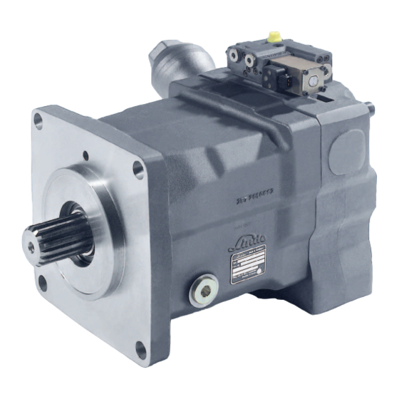
- Page 1 HPR-02. Self-regulating pump for open loop operation.
- Page 2 >> dynamic response >> excellent suction up to rated speed >> noise optimization over the entire range of operation >> optimal interaction with Linde LSC-directional control valves and LinTronic >> compact design >> high power density >> high pressure rating >>...
-
Page 3: Table Of Contents
Data Sheets Linde Hydraulics. Find the right products for your application. Product range Product Application Linde product name Pump Self-regulating pump open loop operation HPR-02 Variable pump closed loop operation HPV-02 Motor Variable motor closed and open loop operation HMV-02... -
Page 4: General Technical Data
Standard Linde-name plate Each Linde Hydraulics unit features a name plate showing the type and the serial number. For a single order via 'open variant' a customer-specific number or free text with up to 15 characters can be stamped on the name plate. - Page 5 General technical data. Selection diagram Input speed [rpm] Suction speeds 1,25 1,15 1,05 0,95 0,85 0,55 0,65 0,75 0,85 0,95 Relative displacement V/ V Ausschwenkung V/V...
-
Page 6: Operational Parameters
Life time recommendations Linde high pressure units are designed for excellent reliability and long service life. The actual service life of a hydraulic unit is determined by numerous factors. It can be extended significantly through proper maintenance of the hydraulic system and by using high-quality hydraulic fluid. -
Page 7: Tank Connection, Filtration, Mounting Orientation
Operational parameters. Tank connection, filtration, mounting orientation Tank connection The leakage and decompression oil generated during pump operation is drained from the rotating group into the pump housing. Excessive housing pressure must be avoided through suitably dimensioned piping between the housing and the tank. Filtration High purity oil can extend the service time of the hydraulic system significantly. -
Page 8: Pressure Fluids
Biodegradable fluids in accordance with ISO 15380 on request >> Other pressure fluids on request Linde offers an oil testing service in accordance with VDMA 24 570 and the test apparatus required for in-house testing. Prices available on request. Recommended viscosity ranges Pressure fluid temperature range [°C]... -
Page 9: Linde Lsc-System
Linde LSC-System. The Linde Synchron Control System (LSC-System) for open loop hydraulic circuits enables demand-orientated pump volume control based on load sensing technology (LS technology). A LSC-System compensates the effect of varying loads, varying numbers of actuators and different load levels at different actuators. This happens automatically, thereby making machine operation more convenient since, unlike in other systems, continuous corrective action is no longer required. -
Page 10: Noise Reduction. Spu Silencer
Noise reduction. SPU silencer All Linde hydraulic pumps are optimized with respect to pulsation characteristics and therefore noise generation. In addition to common primary measures such as exclusive use of pulsation-optimized port plates, Linde Hydraulics offers the SPU silencer for HPR-02 open loop pumps. - Page 11 Noise reduction. SPU silencer SPU silencer function HPR-02 with SPU >> Reduction of pressure pulsations over the entire operating range >> Reduction of noise emission by approx. 50 % (equals approx. 3 dB(A)) >> Reduction of volume flow fluctuations >> No impairment of efficiency >>...
-
Page 12: Torque Transmission
Torque transmission. Depending on the selected components, different torques may be transferred. Please ensure that the load transfer components such as mounting flange, PTO-through shaft and additional pumps are designed adequately. Our sales engineers will be pleased to provide design advice. Torque transmission of HPR-02 This shows the input side (A) and PTO- / output side (B) of a HPR-02 pump. -
Page 13: Mounting Flange
Torque transmission. Mounting flange Mounting Dimensions For rated Mounting flange Torque Torque size in accordance with SAE J744 Washer Screw (8.8) (10.9)* [mm] [mm] [mm] [mm] [mm] [Nm] [Nm] SAE C, 2 hole 55, 75, 105 17x33x10 181.0 SAE C, 2 hole 17x33x10 181.0 with 4 additional threads M12... -
Page 14: Drive Shaft
8/16, 13 t D, E 43.71 16/32, 27 t 44.05 8/16, 15 t 50.06 *) Recommended for tandem configurations A) Linde Hydraulics shaft types Type 1. Without undercut Type 2. With undercut Rated size 105D 165D Excess length W3 61.3... -
Page 15: Pumps According To Iso 3019-2 And Sae J617A
R(B) Linde HPR pumps can be delivered matching a flange according to SAE J617a. The pumps are therefore equipped with an adaptor. Depending on the rated size, the base unit is a standard HPR-02 or a plug-in type HPR-02. The plug-in-flange is shown in section <<Dimensions. -
Page 16: Pto Through Drive
Torque transmission. PTO through drive Linde pumps can be combined into tandem and multiple pumps. The combination options are determined by the permitted transfer torque. The following data refers to the PTO (pump output side, without further attachments). B) Dimensions PTO... -
Page 17: Pto Flange And Output Shaft
B) PTO mounting possibilities Rated size Centring symbol Coupling muff, acc. to SAE J 744 acc. to ANSI B92.1 Directly mounted Linde gear pumps without 16/32 9 t (A) 16/32 11 t 16/32 13 t without 16/32 13 t (B) -
Page 18: Gear Pumps
Zahnradpumpen. Die Zahnradpumpen sind in zwei Bauarten verfügbar: Innenzahnradpumpen IZP und Außenzahnradpump Gear pumps. Kombinationen von und mit IZP und AZP werden durch die PTO-Option und das zulässige Wellendrehmoment b können für den Steuer- und Kühlkreislauf eingesetzt werden. Dabei ist die Sauggrenze von mindestens 0,8 b The gear pumps are available in two designs. - Page 19 Gear pumps. Internal gear pump IGP with external suction PTO flange with IGP Flange profile 2-hole SAE A SAE B SAE B-B SAE C internal spline profile 16/32, 9 t 16/32, 13 t 16/32, 15 t 12/24, 14 t in accordance with ANSI B92.1 D1 spigot pilot diameter 82.55 101.6...
-
Page 20: Controllers
All controllers equipped with load sensing function are fully compatible with the Linde Synchron Control System (see section <<Linde LSC-System>>). -
Page 21: Ls. Load Sensing
Controllers. LS. Load Sensing Linde pumps with load sensing control enable the movement speed required of the selected actuator, e.g. of a boom, to be spe- cified via the valve opening. The measured pump and load pressures are continuously balanced by the load sensing controller of the hydraulic pump. -
Page 22: Lp. Ls With Hydraulic Pressure Cut-Off
Controllers. LP. Load Sensing with hydraulic pressure cut-off In addition to the load sensing function the LP-controller offers maximum pressure limitation. Once the system pressure reaches the set pressure of the pressure cut-off valve, the LS-controller is overridden and the pump swashes back, whilst maintaining the system’s regulating pressure. -
Page 23: E1L/H1L. Ls With Electric/Hydraulic Override
Controllers. E1L/H1L. Load Sensing with electric / hydraulic override In addition to the load sensing function, HPR-02 pumps with H1L or E1L controllers offer the possibility of overriding the ∆p LS-signal hydraulically or electrically. This enables a so called mode control for selecting different operating points or enables a power limit regulation (underspeed control). -
Page 24: E1L. Ls With Electric Override
Controllers. E1L. Load Sensing with electric override In addition to the load sensing function, the HPR-02 E1L offers an electric override for mode selection and power limit regulation (underspeed control). The integration of all functions in the pump controller enables direct signal transfer without delays. The controller-specific data are independent of the nominal pump size. -
Page 25: H1L. Ls With Hydraulic Override
Controllers. H1L. Load Sensing with hydraulic override In addition to the load sensing function, HPR-02 pumps with H1L-controller offer the possibility of overriding the ∆p LS-signal hydraulically. This enables either a so called mode control for selecting different operation points or establish a power limit regula- tion (underspeed control). -
Page 26: Electrical Properties
Controllers. Electrical properties Supply voltage = limiting voltage 100 Hz rectangle, Digital control via Pulse Width Modulation pulse duty ratio variable over control range Control types Direct current with dither overlay (dither Analogue frequency nom. 35 Hz, duty cycle 1:1). Further details on request DIN EN 175301-803, Connector type... -
Page 27: Pump Controllers With Position Feedback
Pump controllers with position feedback TL2-, LEP- and ETP-controllers offer a feedback of the swashplate position. Therefore they are – unlike LP-, E1L- and H1L-controllers – not mounted on the valve plate housing, but on the pump housing. Besides their individual characteristics, these controllers have some similar features. - Page 28 Pump controllers with position feedback T-Axis (TL2/ETP): hydraulic movement of the regulation begin Controllers of the TL2 and ETP type offer a power limitation with a hyperbolical characteristic. The controller is set ex works to a customer specific power limit value. The volume flow is restricted, when this limit is exceeded. By means of control ports at the controller, the point at which the power limiter sets in can be raised, as well as lowered during operation.
-
Page 29: Tl2. Ls With Hyperbolic Power Limitation
Controllers. TL2. Load Sensing with hyperbolic power limitation The control principle with power limitation is used to optimize power utilization of the prime mover in applications where less than the full power capacity is available for the hydraulic system. In addition to the load sensing function the HPR-02 TL2 offers hyperbolic power limitation. -
Page 30: Limitation And Pressure Cut-Off
Controllers. LEP. Load Sensing with electro-proportional flow limitation and pressure cut-off The HPR with LEP-controller offers an on-demand load sensing flow control. The actual volume flow, delivered by the pump can be restricted by an electrical signal in certain points of operation. A pressure cut-off function protects the hydraulic system from overload. -
Page 31: Hyperbolic Power Limitation And Pressure Cut-Off
Controllers. ETP. Electro-proportional flow setting, power limitation and pressure cut-off The HPR with ETP-controller delivers a volume flow which is exactly proportional to the electric control signal. Superposed, the controller offers a hyperbolic power limitation, which optimally exploits the power of the prime mover and also protects it from overload. - Page 32 Dimensions. LP-controller Projekt-Name: HPR-02-A2-LP00_Schaltplan_Katalog_v01 Projekt-Titel: Dokument-Name: Schaltplan_LP Dokument-Titel: Projekt-Ersteller: RA3 - P. Schlee Dokument-Ersteller: RA3 - P.Schlee Reference point Erstellt am : 16.03.2012 13:30:12 Zuletzt gespeichert: 16.03.2012 14:57:47 Towards drive shaft Dimensions: approx. 151 x 105.6 x 37 mm Connections: Test port actuating pressure M14x1.5 LS1, 2...
- Page 33 Dimensions. H1L-controller Reference point Towards drive shaft Projekt-Name: HPR-02-A2-H1L0_Schaltplan_Katalog_v01 Projekt-Titel: Dokument-Name: Schaltplan_H1L Dokument-Titel: Projekt-Ersteller: RA3 - P.Schlee Dokument-Ersteller: RA3 - P.Schlee Erstellt am : 16.03.2012 14:42:37 Zuletzt gespeichert: 16.03.2012 15:02:35 Dimensions: approx. 196.6 x 62.3 x 54.8 mm Connections: Test port control pressure M14x1.5 Test port actuating pressure M14x1.5...
- Page 34 Dimensions. E1L-controller Projekt-Name: HPR-02-A2-E1L0_Schaltplan_Katalog_v01 Projekt-Titel: Reference point Dokument-Name: Schaltplan_E1L Dokument-Titel: Projekt-Ersteller: RA3 - P.Schlee Towards drive shaft Dokument-Ersteller: RA3 - P.Schlee Erstellt am: 16.03.2012 15:03:58 Zuletzt gespeichert: 16.03.2012 15:17:10 Dimensions: approx. 187 x 105.3 x 43.4 mm Connections: Test port control pressure M14x1.5 Test port actuating pressure M14x1.5...
- Page 35 Dimensions. TL2-controller TL2 mit Modeschaltung Z1 + Z2 Projekt-Name: HPR-02-A2-TL20_Schaltplan_Katalog_v01 P rojek t-Tite l: Dokument-Name: Schaltplan_TL2 Dok ume nt-Titel: Projekt-Ersteller: RA3 - P.Schlee Dokument-Ersteller: RA3 - P.Schlee Erstellt am: 16.03.2012 15:34:34 Zuletzt gespeichert: 16.03.2012 15:45:19 Reference point Towards drive shaft Dimensions: approx.
- Page 36 Dimensions. LEP-controller LEP mit Standard DA und Standard LS Projekt-Name: HPR-02-A2-LEP0_Schaltplan_Katalog_v01 Projekt-Titel: Dokument-Name: Schaltplan_LEP Dokument-Titel: Projekt-Ersteller: RA3 - P.Schlee Dokument-Ersteller: RA3 - P.Schlee Erstellt am: 19.03.2012 09:50:09 Zuletzt gespeichert: 19.03.2012 10:38:48 Reference point Towards drive shaft Dimensions: approx. 269.2 x 187.9 x 103.5 mm Connections: Test port actuating pressure M14x1.5...
- Page 37 Dimensions. ETP-controller ETP mit Standard DA und Mode Z1 + Z2 - Schaltung Projekt-Name: HPR-02-A2-ETP0_Schaltplan_Katalog_v01 P rojek t-Tite l: Dokument-Name: Schaltplan_ETP Dok ume nt-Titel: Projekt-Ersteller: RA3 - P.Schlee Dokument-Ersteller: RA3 - P.Schlee Erstellt am: 16.03.2012 15:49:26 Zuletzt gespeichert: 19.03.2012 10:48:34 Reference point Towards drive shaft in Arbeit...
-
Page 38: Single Pumps For Lp, E1L, H1L
Dimensions. Single pumps HPR-02 for LP, E1L, H1L The dimensioning is shown by one exemplary pump configuration. The external dimensions are determined by the individual confi- guration, including the choice of a controller, direction of rotation, optional SPU and the settings of the pump. Further information can be found in the specific sections of this datasheet, in particular the sections <<Torque transmission. - Page 39 Dimensions. Single pumps HPR-02 for LP, E1L, H1L Reference point View 1 Reference point View 2 View 3 View 4 View 5...
-
Page 40: Single Pumps For Tl2, Lep, Etp
Dimensions. Single pumps HPR-02 for TL2, LEP, ETP The dimensioning is shown with one exemplary pump configuration. The external dimensions are determined by the individual configuration, including the choice of a controller, direction of rotation, optional SPU and the settings of the pump. Further infor- mation can be found in the specific sections of this datasheet, in particular the sections <<Torque transmission. - Page 41 Dimensions. Single pumps HPR-02 for TL2, LEP, ETP View 1 Reference point View 2 View 3 Reference point View 4 View 5...
-
Page 42: Double Pumps And Plug-In Pumps
Dimensions. Double pumps and plug-in pumps Double pumps consist of two HPR rotating groups, arranged back-to-back to a common port plate housing, sharing one common suction port. They are thus more compact than two standard pumps in a tandem configuration. Compared to a pump of equal rated size with a single rotating group, double pumps offer higher speed and more narrow radial dimensions. - Page 43 Dimensions. Double pumps and plug-in pumps Plug-in flange SAE bell housing...
-
Page 44: Multiple Pumps
Dimensions. Multiple pumps Multiple pumps are created by connecting individual pump units in series, with the pumps arranged by capacity. Positioning the gear pump(s) at the end of the tandem ensures optimum space utilisation, output allocation and load distribution. The following table is based on the attached gear pump acting as a pilot pressure pump for the control circuit. - Page 45 Dimensions. Multiple pumps Multiple pumps are created by combining individual pump units in series, with the pumps arranged by capacity. Positioning the gear pump(s) at the end of the unit ensures optimum space utilization, output allocation and load distribution. The following table is based on the gear pump acting as boost pump for the HPV-02 variable pump.
-
Page 46: Modular System Features
Modular system features. The HPR-02 is based on a modular system with the following characteristics. This enables our distribution partners to configure the product according to your requirements. The latest characteristics and available options can be taken from the model code, which is available on our homepage. -
Page 47: Print Media Overview
LINC 1. Universal electronic drive control with engine speed control >> LINC 2. Universal electronic drive control >> LSC Linde Synchron Control. Performance meets Flexibility >> Linde pressure definitions. According to DIN 24312 >> eMotion. Electric drives and systems >>... -
Page 48: Contact
Avda. Prat de la Riba, 181, 08780 Palleja (Barcelona), phone +34.9 36 63 32 32, hidraulica@linde-mh.es Fenwick Linde, Activité Linde Hydraulique 1, rue du Maréchal de Lattre de Tassigny, 78854 Elancourt Cedex, Telefon +33.1 30 68 46 47, contact.hydraulics@fenwick-linde.fr (GB) Linde Hydraulics Ltd.
Need help?
Do you have a question about the HPR-2 and is the answer not in the manual?
Questions and answers