SOMFY RTS Instructions Manual
Hide thumbs
Also See for RTS:
- User manual ,
- Operating and installation manual (28 pages) ,
- Instructions (3 pages)
Table of Contents
Advertisement
Quick Links
Advertisement
Table of Contents

Related Manuals for SOMFY RTS


Summary of Contents for SOMFY RTS
- Page 1 Infrared Heater RTS...
-
Page 2: Table Of Contents
5. PROGRAMMING RTS RECEIVER 5.1 PROGRAMMING THE RTS REMOTE TO RECEIVER 5.2 ADDING RTS REMOTE TO MEMORY OF THE RECEIVER 5.3 REMOVING AN RTS REMOTE FROM THE MEMORY OF THE RECEIVER 5.4 TO RESET P 10 6. OPERATING INFRARED HEATER P 10 7. -
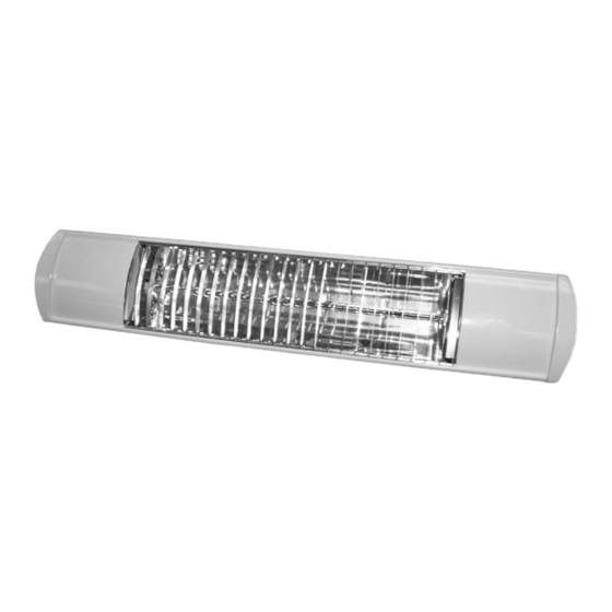
Page 3: Introduction
It is mounted on an adjustable bracket that allows the heat to be directed exactly where it is required. The Infrared Heater RTS is designed for indoor and outdoor use so is therefore weatherproof. -
Page 4: Safety And Responsibilityp
2.1 SAFETY AND RESPONSIBILITY IMPORTANT INSTRUCTIONS When using electrical appliances, basic precautions should always be followed to reduce the risk of fire, electric shock, and injury to persons, including the following: WARNING: RISK OF FIRE KEEP COMBUSTIBLE MATERIALS SUCH AS FURNITURE, PAPERS, CLOTHES AND CURTAINS AT LEAST 6 FEET (1.8M) FROM THE FRONT 1.8m OF THE HEATER AND AWAY FROM THE SIDES AND REAR. - Page 5 ___Unplug the heater during installation, cleaning and/or replacing the light bulb, always ensure that the light bulb is cool. ___Do not handle the halogen light bulb with bare hands. (B) ___If the light bulb (light bulb) is inadvertently touched, remove finger marks with a soft cloth and methylated spirit or alcohol.
-
Page 6: Installation
___ Keep out of the reach of children. 3. INSTALLATION The Infrared Heater RTS is ftted with 16’ 5” (5 meters) of supply cable and a molded plug. If the supply cord is damaged, do not use. -
Page 7: Mounting
4. MOUNTING The heater should always be angled downwards when mounted as shown. Always allow the heater to cool before attempting to reposition/move. Never attempt to move the heater while it is switched on. Ensure the minimum safe distance between the heater body and infammable surfaces and objects when mounting refer to table below and drawing (a). -
Page 8: Mounting W/ Wall Bracket
Securely fasten the Infrared Heater RTS (1) to the wall using the fxing holes in the wall bracket (3). Securely fasten the RTS heat receiver bracket (2) to the wall bracket. Step Two Rotate the heater to the required angled position and tighten... -
Page 9: Mounting W/ Awning Bracket
4.2 MOUNTING WITH AWNING BRACKET (OPTIONAL) Step One Securely fasten the Infrared Heater RTS (1) with the awning mounting bracket (3) (optional) to the square bar (4) of the awning using the fxing holes in the bracket. -
Page 10: Programming Rts Receiver
Step Three Secure the supply cable local to the Infrared Heater RTS using a ‘P’ clip (supplied) so the cable is directed away from the heater and is not resting on the body or obstructing the air-vents. -
Page 11: Adding Rts Remote To Memory Of The Receiver
5.2 ADDING AN RTS REMOTE TO THE MEMORY OF THE RECEIVER First press the programming button on the back of the already programmed remote until the heater lights up, then turns off. Then press the programming button on the remote that... -
Page 12: To Reset
6. OPERATING THE INFRARED HEATER RTS To switch on the Infrared Heater RTS press the UP button of the transmitter. To switch off the Infrared Heater RTS press the DOWN button of the transmitter. -
Page 13: Technical Data
HEATER RTS RECEIVER Radio frequency 433.42 MHz Power supply 120 V/60 Hz Environmental rating IP 67 Operating temperate -20 C to + 70 C Product category Number of RTS control points programmable for 12 maximum one infrared heater RTS P11. -
Page 14: Maintenance
The heating lamp is blown Replace the heating lamp(s) The control point has not Follow the procedure for add- been programmed into ing an RTS control point - see the RTS Receiver section entitled “Adding RTS control points”. Radio interference prevents the... - Page 15 To ensure optimum heat effectiveness, it is recommended that the guard and light bulb are removed and the refector is wiped with a lint-free cloth before reassembling should the refector show considerable signs of dust or dirt. Your Replacement Light Bulb It is very important that your replacement light bulb is exactly the same as the one it was supplied with.
- Page 16 Step Two Remove the heater from its mounting and work on a safe, flat surface. Step Three Remove the screws from the terminal box (Fig. 1) and lift off the cover. Step Four Disconnect the light bulb from the connector blocks by unscrewing the screws highlighted above in Fig.
- Page 17 Step Five Unscrew the four screws (see Fig. 3) from the end cap and remove from the heater body. Repeat at opposite end. Step Six Slide out the side covers from both ends and slide out the guard either end. Step Seven Firstly remove the two screws as highlighted in Fig.
- Page 18 Step Eight Starting at the end where the light bulb wires are fed through the gasket into the terminal box, gently pull the light bulb wires through the body of the heater so the wires exit the terminal box (Fig 6). Step Nine At the opposite end of the heater, gently pull the light bulb...
- Page 19 Step Eleven The light bulb should now be removed from the heater. Reft the new light bulb in reverse order ensuring the ceramic caps are correctly seated in the aluminum light bulb holders, no wires are trapped and all screws are fully tightened.
- Page 20 47 Commerce Drive Cranbury, NJ 08512 Somfy Florida 6100 Broken Sound Pkway, N.W. Suite 14 Boca Raton, FL 33487 Somfy California 15291 Barranca Pkwy Irvine, CA 92618 Somfy Canada 6315 Shawson Drive Unit #1 Mississauga, Ontario L5T1J2 © Somfy Systems, Inc. 3/2009...
Need help?
Do you have a question about the RTS and is the answer not in the manual?
Questions and answers