Table of Contents
Advertisement
Quick Links
PCE Americas Inc.
PCE Instruments UK Ltd.
711 Commerce Way
Units 12/13
Suite 8
Southpoint Business Park
Jupiter
Ensign way
FL-33458
Hampshire / Southampton
USA
United Kingdom, SO31 4RF
From outside US: +1
From outside UK: +44
Tel: (561) 320-9162
Tel: (0) 2380 98703 0
Fax: (561) 320-9176
Fax: (0) 2380 98703 9
info@pce-americas.com
info@pce-instruments.com
www.pce-instruments.com/english
www.pce-instruments.com
Manual
Cable Fault Meter PCE-CL 20
Version 1.0
Date of creation: 09.06.2016
Date of last change: 29.07.2016
Version 1.0
Date of creation: 21.06.2016
Date of last change: 21.06.2016
Advertisement
Table of Contents
Troubleshooting

Related Manuals for PCE Instruments PCE-CL 20


Summary of Contents for PCE Instruments PCE-CL 20
- Page 1 Fax: (561) 320-9176 Fax: (0) 2380 98703 9 info@pce-americas.com info@pce-instruments.com www.pce-instruments.com/english www.pce-instruments.com Manual Cable Fault Meter PCE-CL 20 Version 1.0 Date of creation: 09.06.2016 Date of last change: 29.07.2016 Version 1.0 Date of creation: 21.06.2016 Date of last change: 21.06.2016...
-
Page 2: Table Of Contents
Backlight ............................25 5.3.4 Mute ............................. 25 5.3.5 Automatic shutdown ........................25 Maintenance ......................25 Finding errors / Troubleshooting ....................25 Fuse ............................25 Warranty ......................... 26 Disposal ......................... 26 Contact ........................26 PCE Instruments UK ........................ 26 PCE Americas .......................... 26... -
Page 3: Safety Notes
Please read this manual carefully and completely before you use the device for the first time. The device may only be used by qualified personnel and repaired by PCE Instruments personnel. There is no warranty of damages or injuries caused by non-observance of the manual. -
Page 4: Specification
241.5 x 78 x 38.5 mm Weight Approx. 350 g (incl. batteries) Delivery contents 1 x cable locator PCE-CL 20 (1 x transmitter and 1 x receiver unit) 2 x alligator clips 2 x measuring tips 2 x test leads... -
Page 5: System Description
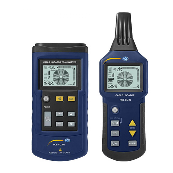
Manual System description Receiver unit Lamp Measuring sensor POWER button Backlight / mute Lamp on / off UAC button Manual / automatic measurement Decrease sensitivity (manual measurement) Increase sensitivity (manual measurement) Speaker Receiver display description Battery voltage receiver Battery voltage transmitter Received transmitting power Symbol for the manual measuring mode Symbol for the automatic measuring mode... - Page 6 Manual Receiver display in cable search mode Automatic measuring mode Manual measuring mode UAC measuring mode (mains voltage identification)
-
Page 7: Transmitter Unit
Manual Transmitter unit POWER-button Set / confirm the transmission power Start / Stop the transmission of the code information Set / confirm the code information DOWN – button UP – button Mute button lamp on / off input / output opening grounding hole Transmitter display description Transmitter battery voltage... -
Page 8: Getting Started
Measurement method The Cable Locator PCE-CL 20 is a two-part instrument, consisting of a transmitter and a receiver unit. Additionally, it comes with a variety of measuring accessories. -
Page 9: Optional Connections To The Cable Locator
Manual Optional connections to the cable locator 4.3.1 Single-pole use The transmitter is connected to only one conductor. Due to the high frequency signal generated by the transmitter, only one conductor can be located and tracked. The second conductor is the ground. This arrangement produces a high-frequency current which flows through the conductor and is transmitted to the ground, similar to a radio or receiver. -
Page 10: Locating And Tracing Of Lines And Sockets
Manual 5.1.2 Locating and tracing of lines and sockets ATTENTION: The circuit must not be live. The neutral cable and the protective grounding cable must be connected and fully functional. Connect the transmitter to the phase cable and the protective grounding cable as shown in the picture below: In case of a single-pole application the lateral circuit branches can be tracked (the fuse must be removed in this example). -
Page 11: Locating The Cable Breaks
Manual 5.1.3 Locating the cable breaks ATTENTION: The circuit must not be live. The cables that are not used, must be connected to the auxiliary ground (as seen in the figure below). Connect the transmitter to the cable connection and to the auxiliary ground. The transition resistance of a cable break must be higher than 100 kΩ. -
Page 12: Detection Of Cable Breaks With The Help Of Two Transmitters
Manual 5.1.4 Detection of cable breaks with the help of two transmitters. In the process of searching for a cable break with a transmitter, which is powered from the end of the cable, the breaks cannot be tracked accurately when bad conditions prevail due to a field disturbance. The impairments described above can be easily avoided if two transmitters (one on each end) are used to detect the cable interruption. -
Page 13: Troubleshooting Of The Underfloor Heating
Manual 5.1.5 Troubleshooting of the underfloor heating ATTENTION: The circuit must not be live. All unused cables must be connected to the auxiliary ground as shown in the following figure. Connect both transmitters in accordance with the figures. If a shielding mat is located above the heating wires, there may be no ground connection. If necessary, disconnect the shield from the ground connection. -
Page 14: Detection Of A Blocked Part In An Installed Non-Metallic Piping
Manual Set the transmission power in order to adapt it to different search radii. The target position can be located accurately by using the manual mode and adjusting the sensitivity. 5.1.6 Detection of a blocked part in an installed non-metallic piping ATTENTION: The pipe must be made of non-conductive materials (such as plastic). -
Page 15: Finding Metallic Tap Water- And Heating Pipe
Manual 5.1.7 Finding metallic tap water- and heating pipe ATTENTION: The pipeline must be made of metallic materials (for example, piping made of galvanized steel). The pipeline must not be grounded. There should be a relatively high resistance between pipe and floor (otherwise the search distance is very small). -
Page 16: Finding Power Supply Circuits On The Same Floor
Manual 5.1.8 Finding power supply circuits on the same floor ATTENTION: Turn off the power in the entire building before measuring. The end of the grounding cable of the transmitter must be grounded properly and should be located at a certain distance from the tracked pipeline. If the distance is too small, the signals and the current circuit cannot be accurately located. -
Page 17: Tracking An Underground Current Circuit
Manual 5.1.9 Tracking an underground current circuit ATTENTION: The power circuit most not be charged. Connect the transmitter as shown in the figure. The end of the grounding cable of the transmitter must be grounded properly. Select the automatic mode on the receiver. Use the displayed signal strength to search and trace the current circuit. -
Page 18: Bipolar Use
Manual Bipolar use 5.2.1 Use in closed current circuits This method can be used in charged and uncharged circuits: In uncharged circuits, the transmitter only sends the encoding signals to the circuit. In charged circuits, the transmitter sends the encoding signals to the circuit, measures and also shows the voltage of the charged circuit, as can be seen in the following figure: ATTENTION: Please follow the safety instructions when connecting the loaded circuits to the transmitter. -
Page 19: Detection Of Fuses
Manual 5.2.2 Detection of fuses In a building with several apartments you use the terminals L and N in the socket of any apartment to provide the flow of the signals from the transmitter, and set the power of the transmitter at an appropriate level. - Page 20 Manual 5.2.2.1 Searching for a short circuit in the current circuit Preparation: The circuit must be unloaded. Connect the transmitter according to the following figure. - If there is current in the cable, first turn the power off to make the cable unpowered. - When searching for short circuits in the coated electric wires and cables the search depths vary, because the core wires in the jacket are twisted with each other.
- Page 21 Manual 5.2.2.2 Finding low-lying current circuits For bipolar use the search depth is strictly limited if the loop / ring cable consists of core wires in cables with multiple core wires (such as, for example, NYM 3 x 1.5 mm²), because a short distance between the supply cable and the loop cable causes a strongly distorted magnetic field.
- Page 22 Manual 5.2.2.3 Classify or define the laid current circuit Preparation: The circuit must be unloaded. The ends of the core wires must be twisted with each other and conduct all together. Connect the transmitter as in the following figure. - If there is current in the cable, first turn off the power to make the cable unpowered. - The ends of the non-shielded core wires must conduct together and need to be twisted with each other.
-
Page 23: Increase Of The Effective Radius When Tracking The Loaded Current Circuits
Manual 5.2.3 Increase of the effective radius when tracking the loaded current circuits When the transmitter is connected directly to the phase cable and the neutral cable, the signals are led to two parallel current circuits. Therefore, the twisting of circuits can sometimes cause signals that counteract each other, which brings to the result that an effective search radius is at most 0.5 m. -
Page 24: Identification Of The Mains Voltage Search Of The Breaks In The Current Circuit
Manual 5.2.4 Identification of the mains voltage search of the breaks in the current circuit Preparation: The circuit must be charged with AC. The measurement must be carried out in accordance with the following figure. Set the transmitter to the mode “mains voltage identification” (UAC-mode). - The found AC signals from the transmitter in the UAC mode only indicate whether the current circuit is charged;... -
Page 25: Backlight
Manual 5.3.3 Backlight The receiver unit is equipped with the backlight option. To activate the backlight, just a corresponding button should be pressed. The transmitter has no backlight function. 5.3.4 Mute On the transmitter, mute function can be activated via the button for muting. After that, the device does not make any sound when the button is pressed. -
Page 26: Warranty
In order to comply with the EU directive 2012/19/EU we take our devices back. We either re-use them or give them to a recycling company which disposes of the devices in line with law. If you have any questions, please contact PCE Instruments. Contact If you have any questions about our range of products or measuring instruments, please contact PCE Instruments.
Need help?
Do you have a question about the PCE-CL 20 and is the answer not in the manual?
Questions and answers