Table of Contents
Advertisement
Quick Links
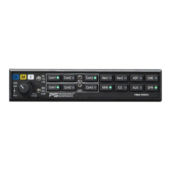
PMA7000H
PMA7000H
Audio Selector Panel
Marker Beacon Receiver and
Stereo Intercom System
Flying Never Sounded So Good™
Pilot's Guide
Pilot's Guide
And
And
Operation Manual
Operation Manual
Patent No. 5,903,277 & 6,160,496
FAA-Approved TSO C50c, C35d
JAA-Approved JTSO 2C35d, C50c
202-780-0429
Revision 1
June 2009
Revision 1, June 2009
202-780-0429
1
Advertisement
Table of Contents

Subscribe to Our Youtube Channel
Related Manuals for PS Engineering PMA7000H Series


Summary of Contents for PS Engineering PMA7000H Series
- Page 1 PMA7000H PMA7000H Audio Selector Panel Marker Beacon Receiver and Stereo Intercom System Flying Never Sounded So Good™ Pilot’s Guide Pilot’s Guide Operation Manual Operation Manual Patent No. 5,903,277 & 6,160,496 FAA-Approved TSO C50c, C35d JAA-Approved JTSO 2C35d, C50c 202-780-0429 Revision 1 June 2009 Revision 1, June 2009 202-780-0429...
-
Page 2: Power Switch (Emg-Fail Safe Operation)
OPERATION SCOPE This section provides detailed operating instructions for the PS Engineering PMA7000H Audio Selector Panel/Intercom Systems. Please read it care- fully before using the equipment so that you can take full advantage of its capabilities. This chapter is divided into four sections covering the basic operating areas of the PMA7000H systems. -
Page 3: Swap Mode (Switch From Com 1 To Com 2 Remotely)
The PMA7000H gives priority to the pilot’s PTT. If the copilot it transmit- ting, and the pilot presses his PTT, the pilot’s microphone will be heard over the selected com transmitter. The PMA7000H-Series has an automatic selector mode. Audio from the selected transceiver is automatically heard in the headsets and speaker (if selected). -
Page 4: Speaker Amplifier
VHF communications signals, and the size constraints in general aviation aircraft, it is probable that there will be some bleed-over in the Split mode, particularly on adjacent frequencies. PS Engineering makes no warranty about of Split Mode in all aircraft conditions. the suitability Note: Split Mode does not turn off other (Nav, ADF, etc.) selected... -
Page 5: Intercom Volume Control
This is normal, for best performance, go fly! For optimum microphone performance, PS Engineering recommends in- stallation of a Microphone Muff Kit from Oregon Aero (1-800-888-6910). This will not only optimize VOX performance, but will improve the overall clarity of all your communications. -
Page 6: Intercom Modes
lose one channel, unless they switch to the “MONO” mode on the headset. Intercom Modes The lower switch on the left side is a 3-position mode switch that allows the pilot to tailor the intercom function to best meet the current cockpit situation. -
Page 7: Entertainment Input
button is activated at that crew station. ICS PTT does NOT affect passenger intercom operation. Entertainment Input The audio selector panel has provisions for two separate entertainment in- put devices. Music 1 feeds the pilot and copilot positions, music 2 feeds the passenger positions. -
Page 8: Telephone Mode
The Com 3 input can serve as a full duplex interface for telephone systems if the installation is correctly configured. Visit www.ps-engineering.com for a list of compatible systems. PS Engineering does not guarantee com- patibility with all cellular or wireless telephone products. -
Page 9: Marker Beacon
Note: Because the telephone uses an intercom circuit, all stations on that circuit will lose intercom capability when the telephone is in use. Marker Beacon The Marker Beacon Receiver uses visual and audio indicators to alert you when the aircraft passes over a 75 MHz transmitter. -
Page 10: Warranty
All domestic transportation charges for returning the exchange or repaired unit to the purchaser will be borne by PS Engineering, Inc. The risk of loss or damage to the product is borne by the party making the shipment, unless the purchaser requests a specific method of shipment. -
Page 11: Factory Service
FAX (865) 988-6619 Email: support@ps-engineering.com NOTE: PS Engineering will not be responsible for any product returned to us by US Mail, or in other than the original or UPS approved equivalent packaging. Units without an RMA or detailed description of problem AND a contact phone number will be refused. - Page 12 Commercial use is strictly prohibited. For further information contact the Publications Man- ager at PS Engineering, Inc., 9800 Martel Road, Lenoir City, TN 37772. Phone (865) 988- 9800...
Need help?
Do you have a question about the PMA7000H Series and is the answer not in the manual?
Questions and answers