Table of Contents
Advertisement
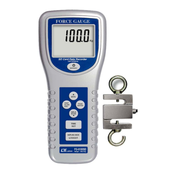
100 Kg
SD Card real time recorder
10 ms sampling time recorder
FORCE GAUGE
Model : FG-6100SD
OPERATION MANUAL
Your
purchase
FORCE GAUGE marks a
step
forward
into the field of precision
measurement.
this FORCE GAUGE is a
complex
and
instrument,
structure will allow many
years of use if proper
operating techniques are
developed.
Please
the following instructions
carefully and always keep
this manual within easy
reach.
of
this
for
you
Although
delicate
its
durable
read
Advertisement
Table of Contents

Subscribe to Our Youtube Channel
Related Manuals for Lutron Electronics FORCE GAUGE FG-6100SD


Summary of Contents for Lutron Electronics FORCE GAUGE FG-6100SD
- Page 1 100 Kg SD Card real time recorder 10 ms sampling time recorder FORCE GAUGE Model : FG-6100SD Your purchase this FORCE GAUGE marks a step forward into the field of precision measurement. Although this FORCE GAUGE is a complex delicate instrument, durable structure will allow many...
-
Page 2: Table Of Contents
TABLE OF CONTENTS 1 FEATURES..............1 2 SPECIFICATIONS............2 3 FRONT PANEL DESCRIPTIONS ........6 3-1 Sensor Input socket..........6 3-2 LCD Display............6 3-3 Power/BACKLIGHT Button........6 /ZERO Button............. ▲ 3-5 FAST/SLOW/ESC Button.........6 3-6 PEAK/ENTER Button..........6 3-7 DISPLAY REVERSE/ Button........▼ 3-8 TIME/SET Button........... - Page 3 5. DATALOGGER............. 11 5-1 Preparation before execute datalogger function..11 5-2 Normal record mode Auto Datalogger ( Set sampling time 1 second )..... ≧ 5-3 Normal record mode Manual Datalogger ( Set sampling time = 0 second )..5-4 Peak hold record mode Fast Datalogger...............
-
Page 4: Features
1. FEATURES * Data record mode : Normal model or Peak hold mode. * Normal record mode : Set sampling time from 1 second to 8 hours. * Peak hold record mode : Set sampling time from 10 ms to 500 ms. * Memory capacity of normal record mode : 1 GB to 16 GB. -
Page 5: Specifications
* Positive or reverse display direction select. * Hand held & stand mounted gauges are available. * Low power consumption gives long battery life. * Build in low battery indicator. * Microprocessor circuit & exclusive load cell transducer. * Over load protection. * RS-232 computer interface * Built-in DC 9V power adapter input socket. - Page 6 Update time Fast Approx. 0.2 second. Slow Approx. 0.6 second. Over range Display show " - - - - " when in over Indicator range status. Normal data Auto 1 sec to 8 hour 59 min. 59 sec. record mode data @ Sampling time can set to 1 second, logger...
- Page 7 Overload Max. 150 kg. Capacity Full Scale Less than 1 mm. Deflection Zero/tare Max. full capacity. Control Sensor type S type load cell. Circuit Exclusive microprocessor LSI-circuit. Power Supply Alkaline or heavy duty DC 1.5 V battery ( UM3, AA ) x 6 PCs, or equivalent. DC 9V adapter input.
- Page 8 Accessories Operating manual ......1 PC. Included 100 Kg sensor with 2 hooks and 2 meter cable....... 1 PC. Carrying case ......1 PC. Optional * T SD memory card ( 2 GB ) Accessories * Test stand, Model : FS-1001 * Electrical test stand, Model : FS-1002 * Wedge grip, Model : WG-01 * RS232 cable, Model : UPCB-02.
-
Page 9: Front Panel Descriptions
3. FRONT PANEL DESCRIPTIONS Fig. 1... -
Page 10: Sensor Input Socket
3-1 Sensor Input socket 3-2 LCD Display 3-3 Power/BACKLIGHT Button /ZERO Button ▲ 3-5 Fast/SLOW/ESC Button 3-6 PEAK/ENTER Button 3-7 DISPLAY REVERSE/ Button ▼ 3-8 TIME/SET Button 3-9 LOGGER/SAMPLING CHECK Button 3-10 RS-232 output terminal 3-11 Reset terminal 3-12 DC 9V Power Adapter Input Socket 3-13 Mounting Holes/fixing Screws 3-14 Battery Cover/Compartment 3-15 Sensor Hooks... -
Page 11: Measuring Procedure
4. MEASURING PROCEDURE 4-1 Pay attention for the measurement 1) Compression measurement, the display will show the " - " mark automatically. Tension Compression 2) During the measurement, the SENSING HEAD along the adapter has to be on a line with measuring object. ( ref. -
Page 12: Normal Measurement
3) Rotate the SENSING HEAD is prohibited. Some certain angles between SENSING HEAD & measuring object are not allowed. 4-2 Normal Measurement Power on/off Power on : Press " Power Button " ( 3-3, Fig. 1) once. Power off : During power on, press "... -
Page 13: Peak Hold Measurement
5) Start measurement by giving force (push or pull), then the LCD will display the Average reading value. Note : * During the measurement, if intend to change the display direction, just push the " Reverse Button " ( 3-7, Fig. 1 ) once. * There are two kind sampling time of display, FAST and SLOW. -
Page 14: Datalogger
4-4 LCD Back Light On/Off During the measurement, press the " BACKLIGHT Button " ( 3-3, Fig. 1 ) once the LCD Back Light will be ON. During the LCD Back Light ON, press the " BACKLIGHT Button " once again, the LCD Back Light will be OFF again. 4-5 Alarm beeper If the measuring value over the 100.00 Kg, the internal buzzer will sound for warning. -
Page 15: Normal Record Mode Auto Datalogger
d. Decimal format setting The numerical data structure of SD card is default used the " . " as the decimal, for example "20.6" "1000.53" . But in certain countries ( Europe ...) is used the " , " as the decimal point, for example "... -
Page 16: Normal Record Mode Manual Datalogger ( Set Sampling Time = 0 Second )
b. Pause the datalogger During execute the Datalogger function , if press the " Logger Button " ( 3-9, Fig. 1 ) once will pause the Datalogger function ( stop to save the measuring data into the memory circuit temporally ). In the same time the indicator of "... -
Page 17: Peak Hold Record Mode Fast Datalogger
Remark : During execute the Manual Datalogger, press the " ▲ Button " ( 3-4, Fig, 1 ) or " Button " ( 3-7, Fig. 1 ) to ▼ set the measuring Location no. ( 1 to 99, for example room 1 to room 99 ) to identify the measurement location , the lower Display will show P x ( x = 1 to 99 ). -
Page 18: Check Time Information
* When the peak value is got, the LCD indicator " DATA RECORD " will be disappeared . The indicator will show " PEAK " indicator only, in the same time the peak value will freeze on the Display * Following the bottom LCD will show the data record no. - Page 19 2) If the first time to execute the Datalogger, under the route FGC01\, will generate a new file name FGC01001.XLS. After exist the Datalogger, then execute again, the data will save to the FGC01001.XLS until Data column reach to 30,000 columns, then will generate a new file, for example FGC01002.XLS 3) Under the folder FGC01\, if the total files more than 99 files, will generate anew route, such as...
-
Page 20: Saving Data From The Sd Card To The Computer
6. Saving data from the SD card to the computer ( EXCEL software ) 1) After execute the Data Logger function, take away the SD card out from the " SD card socket " ( 3-20, Fig. 1 ). 2) Plug in the SD card into the Computer's SD card slot ( if your computer build in this installation ) or insert the SD card into the "... - Page 21 EXCEL data screen ( for example, peak hold record mode ) EXCEL graphic screen ( for example, graphic 1 )
-
Page 22: Advanced Setting
EXCEL graphic screen ( for example, graphic 2 ) 7. ADVANCED SETTING Under do not execute the Datalogger function, press the " SET Button " ( 3-8, Fig. 1 ) continuously at least two seconds will enter the " Advanced Setting " mode. then press the "... - Page 23 Remark : During execute the " Advanced Setting " function, if press " ESC Button " ( 3-5, Fig. 1 ) will exit the " Advanced Setting " function, the LCD will return to normal screen. 7-1 SD memory card Format When the lower display show "...
- Page 24 2) After set all the time value ( Year, Month, Date, Hour, Minute, Second ), press the " SET Button " ( 3-8, Fig. 1 ) once will save the time value, then the screen will jump to Sampling time " setting screen ( Chapter 7-3 ). Remark : After the time value is setting, the internal clock will run precisely even Power off if the battery is under...
- Page 25 7-4 Set sampling time for peak record mode When the lower display show " HSPt " 1) Use the " Button " ( 3-4, Fig. 1 ) or " Button " ▲ ▼ ( 3-7, Fig. 1 ) to adjust the value ( adjust unit is milli seconds, each step is 10 ms, setting start from 10 ms ).
- Page 26 7-6 Set beeper sound ON/OFF When the lower display show " bEEP " 1) Use the " Button " ( 3-4, Fig. 1 ) or " Button " ▲ ▼ ( 3-7, Fig. 1 ) to select the upper value to " yES " or "...
- Page 27 7-8 Decimal point of SD card setting The numerical data structure of SD card is default used the " . " as the decimal, for example "20.6" "1000.53" . But in certain countries ( Europe ...) is used the " , " as the decimal point, for example "...
-
Page 28: Power Supply From Dc Adapter
8. POWER SUPPLY from DC ADAPTER The meter also can supply the power supply from the DC 9V Power Adapter ( optional ). Insert the plug of Power Adapter into " DC 9V Power Adapter Input Socket " ( 3-12, Fig. 1 ). The meter will permanent power ON when use the DC ADAPTER power supply ( The power Button function is disable ). -
Page 29: Rs232 Pc Serial Interface
11. RS232 PC SERIAL INTERFACE The instrument has RS232 PC serial interface via a 3.5 mm terminal ( 3-10, Fig. 1 ). The data output is a 16 digit stream which can be utilized for user's specific application. A RS232 lead with the following connection will be required to link the instrument with the PC serial port. -
Page 30: Mounting Holes & Optional Test Stand
Polarity 0 = Positive 1 = Negative Decimal Point(DP), position from right to the left 0 = No DP, 1= 1 DP, 2 = 2 DP, 3 = 3 DP D8 to D1 Display reading, D1 = LSD, D8 = MSD For example : If the display reading is 1234, then D8 to D1 is : 1234 End Word... -
Page 31: Applications
b. 150 Kg capacity ELECTRICAL TEST STAND for Force gauge Model : FS-1002-110V, FS-1002-220V * Max. capacity : 150 Kg ( 330 lb.. ). * Max. tension distance : 450 mm. * Net weight : 17.6 Kg. * Size ( WDH ) : 220 mm x 280 mm x 800 mm. - Page 32 13-2 Business Equipment * Measure force required to perforate cards. * Measure load on slitter knives. * Measure actuating requirements of typewriter. * Test clutch release force. * Measure torque, timing belt tension (by deflection), sliding friction, etc., on computer peripheral equipment. * Test adhesion strength of labels and stickers.
- Page 33 13-5 Automotive * Measure force of seat belt retractors. * Measure arm pressure of windshield wipers. * Measure flip force in mechanical snap action switches. * Test effort to operate hand tool. * Test forces required to move linkages and tension cables. * Measure force of odometer pull.
Need help?
Do you have a question about the FORCE GAUGE FG-6100SD and is the answer not in the manual?
Questions and answers