Table of Contents
Advertisement
1
SAFETY ........................................................ 2
2
INSTALLATION ............................................ 3
2.1
Basic installation ................................................................ 3
2.2
Exhaust vents...................................................................... 3
2.3
Feet (leveling legs).............................................................. 3
®
2.4
(aqua secure)................................................ 4
2.5
General installation warnings ............................................ 4
3
OPERATION ................................................. 5
3.1
Controls ............................................................................... 5
4
COMPONENTS............................................. 6
4.1
WTVC Gas Dryer Components .......................................... 6
4.2
Operation ........................................................................... 14
5
REPAIR....................................................... 15
5.1
Disassembly / Reassembly .............................................. 15
5.2
Kit Installation ................................................................... 25
5.3
Diagnosing (troubleshooting).......................................... 26
5.4
Dryer noise ........................................................................ 27
5.5
Customer diagnosing ....................................................... 27
5.6
Maintenance ...................................................................... 28
6
FAULT DIAGNOSTICS............................... 29
6.1
Overheating fault codes ................................................... 32
7
TECHNICAL SPECIFICATIONS ................ 33
W
T
V
C
G
A
S
D
R
Y
E
R
R
E
P
A
I
R
W
T
V
C
G
A
S
D
R
Y
E
R
R
E
P
A
I
R
W
T
V
C
G
A
S
D
R
Y
E
R
R
E
P
A
I
R
I
N
S
T
R
U
C
T
I
O
N
I
N
S
T
R
U
C
T
I
O
N
I
N
S
T
R
U
C
T
I
O
N
7.1
Dryer ratings ..................................................................... 33
Advertisement
Table of Contents

Related Manuals for Bosch WTVC SERIES


Summary of Contents for Bosch WTVC SERIES
-
Page 1: Table Of Contents
SAFETY ............2 Dryer ratings ..............33 INSTALLATION ..........3 Basic installation ..............3 Exhaust vents..............3 Feet (leveling legs).............. 3 ® AQUASTOP (aqua secure)..........4 General installation warnings ..........4 OPERATION ..........5 Controls ................5 COMPONENTS..........6 WTVC Gas Dryer Components .......... 6 Operation ................ -
Page 2: Safety
SAFETY c Danger of electric shock. h Danger of fire or explosion from gas. WARNING Modern appliances are very powerful and use high technology devices to safely control that power. Failure to use the correct procedures and the approved parts can create serious hazards for the person servicing the appliance and for the user of an appliance with a bad repair. -
Page 3: Installation
Use the table below when selecting ducting. INSTALLATION # 90º Turns / Maximum Length Basic installation Elbows Rigid Duct Flexible Duct 20 m 14 m Dryers shall be installed according to national and local codes. 17 m 11 m 14.5 m Exhaust vents 12 m 2.2.1... -
Page 4: Aquastop ® (Aqua Secure)
® AQUASTOP (aqua secure) ® AQUASTOP water inlet hoses prevent water from leaking. They connect like standard hoses with no special installation needed. If an inner hose ever should leak, the hose shuts off and it’s indicator shows red. Hoses are one-time and must be replaced when indicators are red. -
Page 5: Operation
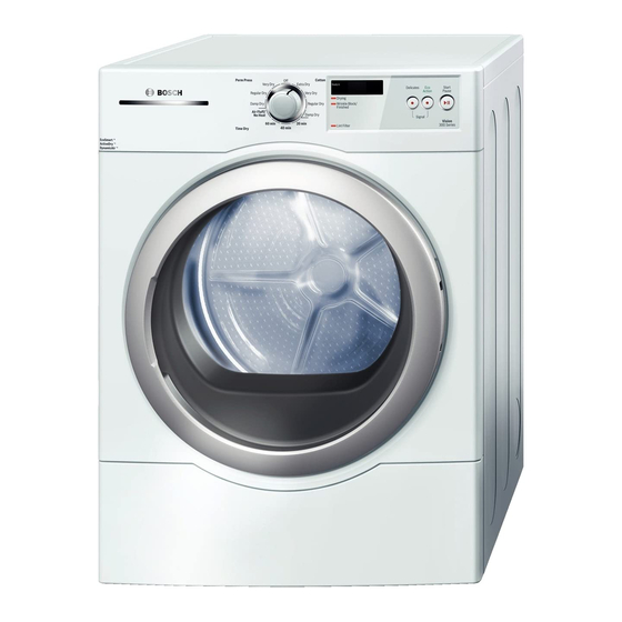
There are option buttons for delicate fabrics and saving energy. Dryer OPERATION status is shown in LED’s at the left of the display. Controls Controls are shown below. Rotate the knob to the desired drying program and push the Start/Pause button. 702_58300000143767_ara_en_a Page 5 of 33... -
Page 6: Components
COMPONENTS 4.1.1 Gas burner assembly Burner assemblies include an NTC temperature sensor and a WTVC Gas Dryer Components manually resettable hi-limit temperature protector. The NTC is mounted at the rear of the assembly near where it attaches to the Basic components are control module, gas burner, gas igniter, flame vent. - Page 7 4.1.2 Drive motor 4.1.4 Burner The burner mounts next to the gas valve jet (orifice). A burner ring is used for natural gas dryers to optimize performance. Motor is rated 120 VAC, 60 Hz, 1/3 HP (248.5 W), 5.0 A, 1725 RPM, 40ºC...
- Page 8 5. If bubbles form around the brass connector or on the gas valve 4.1.7 Flame sensor itself, replace the leaking valve with a new one and repeat steps 3, 4 and 6. Flame sensors detect flame out in 30 – 60 seconds and direct the igniter to reignite flames.
- Page 9 4.1.9 Broken belt switch 4.1.10 Air exhaust duct The broken belt switch prevents the dryer from running if the belt has Air exhaust duct connects to the fan and allows exhausting through broken or been left disconnected. It must be manually reset (by the rear of dryers.
- Page 10 4.1.12 Moisture sensor 4.1.14 Fan wheel replacement Moisture sensor consists of two electrodes (located just left of the lint Even though WTVC and WTMC dryers use the same fan motor, they screen on the front bearing shield). Moisture from clothes completes do not use the same fan.
- Page 11 ® A cold water inlet valve similar to washers is used. 4.1.16 AQUASTOP (aqua secure) inlet hoses ® Hot and cold water AQUASTOP inlet hoses eliminate leaking. The ® AQUASTOP hose consists of an inner hose (~ inlet water tubing) and an outer hose (corrugated, ~ to drain hoses).
- Page 12 4.1.17 Round button assembly 4.1.19 Front felt drum seal The three (3) round buttons are joined by delicate plastic rods. Be Dryers have a self-adhesive, Teflon coated, felt front seal which can careful installing or removing buttons so button joining rods aren’t be replaced.
- Page 13 4.1.21 Wrinkle Block/Finished light If the Wrinkle Block/Finished light is on while the display is off, an internal switch (S3) on the control board has been damaged and the entire control module has to be replaced. 4.1.22 Serial # label The serial # label is located below the door and shows the model (E- Nr) and serial # of the dryer.
-
Page 14: Operation
(connected to the water line) absorbs water, pulling a plunger down to Operation stop water flow and show in the indicator window. The outer hose is sealed and won’t leak. 4.2.1 Gas burner operation Flame sensor (N.C.) Igniter coil valve Booster coil Holding coil (120V) -
Page 15: Repair
REPAIR 5.1.3 Control module Remove control module from fascia panel progressively from left to Disassembly / Reassembly right, carefully releasing all plastic latches (so latches don’t break). Gently pry up left side of control so latches don’t re-close. Control will 5.1.1 Top panel (worktop) release from fascia panel and knob. - Page 16 5.1.5 Round button assembly Don’t cut cable mounts – cut cable The (clear) round button assembly is connected by delicate plastic ties holding cables to mounts. rods. When removing buttons, gently pry out and remove them as a When reassembling, use new group, not individually.
- Page 17 Remove two (2) M4.2x19 T-20 Torx latch cover screws and remove 5.1.7 Door removal the latch cover and latch out from the door. To remove the door from the front panel, open the door, remove four (4) M4.2x19 T-20 Torx hinge cover screws, remove the hinge cover and lift the door up and away from the panel.
- Page 18 Lift the door glass and the inner ring from the door. 1) Remove door (5.1.7) and place it (front side down) on a protected surface to avoid scratching the outer door frame and door glass. Make sure hinge plastic bushings remain on the hinge. 2) Disassemble door (5.1.8) until only outer door frame and outer door glass cover remain, including removing single screws under the hinge and latch covers.
- Page 19 4) Lift up the outer door glass and rotate it 90º clockwise. Don’t Be sure to reinstall the single screws under the latch and hinge cover rotate the outer door frame. plates. 90º 6) Move latch (to left side) and reassemble door latch cover. 5) Reassemble all parts in the same position and order they were disassembled (inner ring, glass bowl, inner frame) –...
- Page 20 There is a retainer latch (“catch”) in both the left and right sides so 10) Place door onto hinge and reinstall door hinge cover with four (4) there’s no need to move them. screws to secure door to dryer. 8) Remove hinge from right side of dryer by removing two (2) screws and lifting the hinge up and away from the dryer.
- Page 21 5.1.11 Drum and drum cover (with drum bearing) 1) Remove rear panel (5.1.10). 2) Disconnect belt (from motor pulley) to remove belt tension. Disconnecting belt 5.1.12 Gas valve and burner 3) Remove dryer shaft clip and two T-20 Torx drum cover screws, valve then lift cover from dryer.
- Page 22 6) Remove burner screws, including screws holding burner 5.1.14 Front panel bracket to base and combustion chamber and screws holding burner to bracket. 1) Remove fascia panel (5.1.2). If necessary for access, remove top panel (5.1.1). 5.1.13 Motor, belt tensioner and broken belt switch 2) Remove door (5.1.7) and door hinge (5.1.9.8).
- Page 23 8) If needed, remove drum support wheels. 5.1.15 Front bearing shield 1) Remove front panel screws, but don’t remove panel itself (5.1.14). If necessary for access, remove top panel (5.1.1). 2) Remove door (5.1.7), door hinge (5.1.9.8) and front panel latch cover (5.1.9.7) to expose all front bearing shield screws.
- Page 24 5.1.17 Fan Remove front panel (5.1.14) and bearing shield (5.1.15). Remove fan front cover to access fan. Fan is located on front of motor shaft, which has left-handed thread. To remove fan from motor shaft, use a 1” wrench and rotate fan (clockwise) from left to right. Turn fan clockwise (cw) to loosen (i.e.
-
Page 25: Kit Installation
5. Remove burner chamber & burner, then remove burner ring Kit Installation from burner (as its not needed for LP). 5.2.1 LP valve conversion kit 6. Remove natural gas valve and replace with LP gas valve. Install LP rating plate and conversion labels. 5.2.1.1 Using WTZ1280 LP kit 7. -
Page 26: Diagnosing (Troubleshooting)
Diagnosing (troubleshooting) Problem Possible Causes Suggested Repairs Dryer won't run Power not on or has been disconnected. Reconnect and turn on power. Door switch misaligned & doesn't get activated by door pin. Tighten screw (where door pin engages door switch) to realign front shield with door. Do not overtighten screw. -
Page 27: Dryer Noise
Dryer noise Customer diagnosing Dryer has a noise Problem Possible cause Remedial action Dryer doesn’t Main plug not inserted or not Insert main plug correctly. Is dryer level? start. inserted correctly. Level dryer Start/Pause A power supply fuse has Replace fuse/turn on breaker. indicator light blown or circuit breaker has Remove rear panel and run the dryer a few minutes to find the noise... -
Page 28: Maintenance
tart/Pause Fault in program sequen ce or Turn of f dryer, leave to cool for 30 Maintenance indicator light malfunction. min. and then turn on again. doesn’t Restart program. illuminate. 5.6.1 Cleaning lint filter Anti Crease/end The lint filter should be cleaned after each use. The Filter light comes indicator on after each cycle and when the door is open (while the dryer is lights. -
Page 29: Fault Diagnostics
1. Safety test FAULT DIAGNOSTICS For the safety test must Heater Element (at least on one side with the phase ) switch on. The test must be done using different current method. For this propose the following Inspection Proces s is adaptive Connect appliance with tester and power line 2. - Page 30 LEDs (Indicator) Display Fault / fault Remarks, possible Results description cause Drying Iron dry Cupboard LEDs Position or display is flashing E:18 Heater-NTC fault - No temperature rise - Check heater circuit and symbol (TH) after starting a program, bimetal switch, replace break in heater circuit, damaged parts Iro Dry...
- Page 31 Test descriptio LED or disp lay symbol L ED or Dis y symbol R arks: 2.8 Changeover 10A/16A (208V/240V) operation (EU: not used, function without any Drying Iron Dry effect - Drum empty, no Fault ! There is a bypass in measuring circuit. Test: eque ce: Dis lay:...
-
Page 32: Overheating Fault Codes
Failure Code fo he li ne test program LED-> dryin damp dry regular dry extra dry lint filter NTC in th e exha E:17 channel NTC above the E:18 heater Overheating E:11 und E:12 Conductance error(*) Overheating fault codes If burner or lint screen NTC’s detect overheating (e.g. from clogged vent ducts), an E:01 fault code will appear during drying. -
Page 33: Dryer Ratings
TECHNICAL SPECIFICATIONS 7.1.5 Energy factor Dryer ratings EF ≥ 2.67 lbs./kwh. 7.1.6 Duct length (max.) 7.1.1 WTVC gas dryer ratings 66’ (20 m) of 4” rigid metal duct. 120VAC, 15A, 60 Hz, 1500W (12A max.). 3/8” NPT (female) gas 7.1.7 Gas igniter ratings connection.
Need help?
Do you have a question about the WTVC SERIES and is the answer not in the manual?
Questions and answers