
Related Manuals for Fleck 7000SXT


Summary of Contents for Fleck 7000SXT
- Page 1 Model 7000SXT Service Manual IMPORTANT: Fill in Pertinent Information on Page 3 for Future Reference...
-
Page 2: Table Of Contents
Table of Contents Job Specification Sheet ............................3 Installation Instructions ............................4 Start-Up Instructions .............................. 5 Timer Features ..............................6 Timer Operation ..............................9 Master Programming Mode Chart ........................11 Master Programming Mode ..........................13 User Programming Mode ............................ 19 Diagnostic Programming Mode ........................... 20 Powerhead Assembly ............................ -
Page 3: Job Specification Sheet
Job Specification Sheet Job Number: __________________ Model Number: ________________ Water Hardness: ___________________ ppm or gpg Capacity Per Unit: ______________ Mineral Tank Size: ___________ Diameter: ___________ Height: Salt Setting per Regeneration: _____________________________________________ Type of Timer: 7 Day or 12 Day B. Meter Initiated Downflow Upflow Upflow Variable... -
Page 4: Installation Instructions
Installation Instructions WATER PRESSURE: A minimum of 20 psi (1.3 bar) of water pressure is required for regeneration valve to operate effectively. ELECTRICAL FACILITIES: An uninterrupted alternating current (A/C) supply is required. Note: Other voltages are available. Please make sure your voltage supply is compatible with your unit before installation. EXISTING PLUMBING: Condition of existing plumbing should be free from lime and iron buildup. -
Page 5: Start-Up Instructions
Start-Up Instructions The water softener should be installed with the inlet, outlet, and drain connections made in accordance with the manufacturer’s recommendations, and to meet applicable plumbing codes. NOTE: The valve control may need to reset to the home position when it is powered up. If it does, the motor will run and the display will read “UD SYNC”... -
Page 6: Timer Features
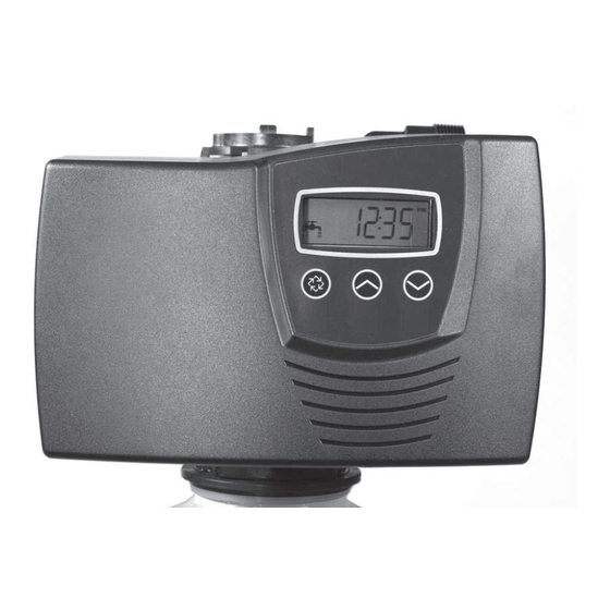
Timer Features Parameter Data Display Display Indicator Error/ Information Icon Flow Indicator Service Icon x1000 Indicator Programming Icon Extra Cycle Down Button Button Button Features of the SXT: • Power backup that continues to keep time and the passage of days for a minimum of 48 hours in the event of power failure. - Page 7 Timer Features Queueing a Regeneration Press the Extra Cycle button. The service icon will flash to indicate that a regeneration is queued. To cancel a queued regeneration, press the Extra Cycle button. Regenerating Immediately Press and hold the Extra Cycle button for five seconds. Page 7...
-
Page 8: Timer Operation
Timer Operation Meter Immediate Control A Meter Immediate Control measures water usage and regenerates the system as soon as the calculated system capacity is depleted. The control calculates the system capacity by dividing the unit capacity (typically expressed in grains/unit volume) by the feedwater hardness and subtracting the reserve. Meter Immediate systems generally do not use a reserve volume. - Page 9 Timer Operation Manually Initiating a Regeneration When timer is in service, press the Extra Cycle button for 5 seconds on the main screen. The timer advances to Regeneration Cycle Step #1 (backwash), and begins programmed time count down. Press the Extra Cycle button once to advance valve to Regeneration Cycle Step #2 (brine draw & slow rinse). Press the Extra Cycle button once to advance valve to Regeneration Cycle Step #3 (backwash).
-
Page 10: Master Programming Mode Chart
Master Programming Mode Chart Master Programming Options Abbreviation Parameter Option Options Abbreviation Gallons Display Format Liters Cubic Meters St1b Standard Downflow/Upflow Single Backwash (Not Used) St2b Standard Downflow/Upflow Double Backwash (7000 Default) Fltr Filter (7000 Default) UFbF Upflow Brine First (Not Used) Valve Type 8500 TwinFlo100SXT (Not Used) - Page 11 Master Programming Mode Chart Master Programming Options Current Day The Current day of the week t0.7 3/4” Turbine Meter P0.7 3/4” Paddle Wheel Meter t1.0 1” Turbine Meter Flow Meter Type P1.0 1” Paddle Wheel Meter t1.5 1.5” Turbine Meter (7000 Default) P1.5 1.5”...
-
Page 12: Master Programming Mode
Master Programming Mode When the Master Programming Mode is entered, all available option setting displays may be viewed and set as needed. Depending on current option settings, some parameters cannot be viewed or set. Setting the Time of Day Press and hold either the Up or Down buttons until the programming icon replaces the service icon and the parameter display reads TD. - Page 13 Master Programming Mode 2. Valve Type (Display Code VT) Press the Extra Cycle button. Use this display to set the Valve Type. The Valve Type setting specifies the type of cycle that the valve follows during regeneration. Note that some valve types require that the valve be built with specific subcomponents.
- Page 14 Master Programming Mode 5. Tank in Service (Display Code TS) Press the Extra Cycle button. Use this display to set whether tank one or tank two is in service. This option setting is identified by “TS” in the upper left hand corner of the screen. This parameter is only available if the number of tanks has been set to 2.
- Page 15 Master Programming Mode 8. Reserve Selection (Display Code RS) Press the Extra Cycle button. Use this display to set the Safety Factor. Use this display to select the type of reserve to be used in your system. This setting is identified by “RS” in the upper left-hand corner of the screen. The reserve selection parameter is only available if the control type has been set to one of the metered options.
- Page 16 Master Programming Mode 11. Day Override (Display Code DO) Press the Extra Cycle button. Use this display to set the Day Override. This setting specifies the maximum number of days between regeneration cycles. If the system is set to a timer-type control, the day override setting determines how often the system will regenerate.
- Page 17 Fleck 1” Turbine Meter P1.0 Fleck 1” Paddle Wheel Meter t1.5 Fleck 1 1/2” Turbine Meter (7000 Default) P1.5 Fleck 1 1/2” Paddle Wheel Meter Generic/Other Meter CAUTION: Before entering Master Programming, please contact your local professional water dealer.
- Page 18 Master Programming Mode 17. Meter Pulse Setting (Display Code K) Press the Extra Cycle button. Use this display to specify the meter pulse setting for a non-standard flow meter. This option setting is identified by “K” in the upper left-hand corner of the screen. Use the Up and Down buttons to enter the meter constant in pulses per unit volume.
-
Page 19: User Programming Mode
User Programming Mode User Programming Mode Options Abbreviation Parameter Description Day Override The timer’s day override setting Regeneration Time The time of day that the system will regenerate (meter delayed, timeclock, and day-of-week systems) Feed Water Hardness The hardness of the inlet water - used to calculate system capacity for metered systems Reserve Capacity... - Page 20 User Programming Mode Press the Extra Cycle button. Use this display to adjust the Fixed Reserve Capacity. This option setting is identified by “RC” in the upper left-hand Corner of the screen. Press the Extra Cycle button. Use this display to set the Current Day of the Week. This option setting is identified by “CD”...
-
Page 21: Diagnostic Programming Mode
Diagnostic Programming Mode Diagnostic Programming Mode Options Abbreviation Parameter Description Flow Rate Displays the current outlet flow rate Peak Flow Rate Displays the highest flow rate measured since the last regeneration Hours in Service Displays the total hours that the unit has been in service Volume Used Displays the total volume of water treated by the unit Reserve Capacity... - Page 22 Diagnostic Programming Mode Press the Up button. Use this display to view the Reserve Capacity. This option setting is identified by “RC” in the upper left hand corner of the screen. Press the Up button. Use this display to view the Software Version. This option setting is identified by “SV” in the upper left hand corner of the screen.
- Page 23 Notes Page 23...
-
Page 24: Powerhead Assembly
Powerhead Assembly BR61501-7000SXT Page 24... - Page 25 Powerhead Assembly Item No. Quantity Part No. Description 1 ......1 ...... 10218 ......Switch, Micro (Optional) 2 ......1 ...... 40978 ......Support, Upper Bearing 3 ......1 ...... 61696 ......Circuit Board 4 ......1 ...... 40702 ......Shaft, Drive/Encoder 5 ......1 ...... 40703 ......Gear, Main Drive 6 ......1 ......
-
Page 26: Valve Assembly
Valve Assembly 61500-7000EXP_REVC Item No. Quantity Part No. Description 1 ......1 ......61050 ......Valve Body Assembly, 7000, 32 mm Dist 2 ......1 ......61452-10 ...... Piston Assembly, 7000, Softener, D/F 35 gpm 61453-10 ...... Piston Assembly, 7000, Softener, D/F 28 gpm 61452-20 ...... - Page 27 Valve Assembly Parts List Item No. Quantity Part No. Description 8 ......1 ......40556 ......... Cap, Injector 9 .............61450-00 ......BLFC 3/8”, Blank ..............61450-12 ......BLFC 3/8”, 0.125 gpm ..............61450-25 ......BLFC 3/8”, 0.25 gpm ..............61450-50 ......BLFC 3/8”, 0.50 gpm ..............61450-100 ......
-
Page 28: Bypass Assembly
Bypass Assembly 41118_REVA 41147_REVA IMPORTANT To bypass the valve, turn bypass knob on both sides of the valve to bypass position. When returning to service, put the inlet into service before the outlet. Item No. Quantity Part No. Description 1 ......1 ....40569 ..... Bypass Assembly, 7000, Less Clip 2 ......2 .... -
Page 29: 2310 Safety Brine Valve
2310 Safety Brine Valve Item No. Quantity Part No. Description 1 ....1 ......19645 ......Body, Safety Brine Valve, 2310 2 ....1 ......19803 ......Safety Brine Valve Assy 3 ....1 ......19804 ......Screw, Sckt Hd, Set, 10-24 x .75 4 ....1 ......19805 ......Nut, Hex, 10-24, Nylon Black 5 ....1 ......19652-01 .... -
Page 30: Troubleshooting
Troubleshooting Problem Cause Correction 1. Water conditioner fails to A. Electrical service to unit has A. Assure permanent electrical service regenerate. been interrupted (check fuse, plug, pull chain, or switch) B. Timer is defective. B. Replace timer. C. Power failure. C. - Page 31 Troubleshooting Problem Cause Correction 8. Softener fails to draw brine. A. Drain line flow control is A. Clean drain line flow control. plugged. B. Injector is plugged. B. Clean injector C. Injector screen plugged. C. Clean screen. D. Line pressure is too low. D.
- Page 32 Troubleshooting Error Codes Note: Error codes appear on the In Service display. Error Error Type Cause Reset and Recovery Code Cam Sense The valve drive took longer Unplug the unit and examine the powerhead. Verify Error than 6 minutes to advance to that all cam switches are connected to the circuit the next regeneration position.
-
Page 33: Removing Gear Box Assembly
Removing Gear Box Assembly 40988_REVA 1. Unplug the power source. 2. With 3/8” nut driver, turn the cycle cam counter-clockwise to the position shown in illustration above. 3. Slightly pull the two tabs outward and push the gearbox slightly upward to remove. 4. -
Page 34: Inserting Circuit Board
Inserting Circuit Board 41033_REVB 1. To insert the circuit board, align the notches on the left side of the board with the flexible finger on the power head. Apply pressure to the left while rotating the board back. 41033_REVB 2. When all the way down, snap the circuit board into place under the notches on the right. Page 34... -
Page 35: Connecting The Circuit Board
Connecting the Circuit Board 41033_REVB After the circuit board is installed: 1. Connect the motor wires (A) to the motor connector (A1) on board. 2. Connect the transformer cable (B) to the transformer connector (B1) on board. 3. Connect the meter cable (C) to the meter cable connector (C1) on board. 4. -
Page 36: Water Conditioner Flow Diagrams
Water Conditioner Flow Diagrams In Service Position 40988_REVA 41121_REVA Backwash Position 40988_REVA 41121_REVA Page 36... - Page 37 Water Conditioner Flow Diagrams Brine Position 40988_REVA 41121_REVA Slow Rinse Position 40988_REVA 41121_REVA Page 37...
- Page 38 Water Conditioner Flow Diagrams Rapid Rinse Position 40988_REVA 41121_REVA Brine Tank Refill Position 40988_REVA 41121_REVA Page 38...
-
Page 39: Injector Flow Data
Injector Flow Data TR18755_REVB Page 39... -
Page 40: Meter Flow Data
Meter Flow Data TR18753 Softener TR18688 Filter 41140-02_REVA Page 40... -
Page 41: Dimensions
Dimensions 41023_REVC Page 41... - Page 42 Notes Page 42...
Need help?
Do you have a question about the 7000SXT and is the answer not in the manual?
Questions and answers