Table of Contents
Advertisement
It is of vital importance, before attempting to operate
your engine, to read the general 'SAFETY
INSTRUCTIONS AND WARNINGS' section on
pages 2-6 of this booklet and to strictly adhere to the
advice contained therein.
Also, please study the entire contents of this
instruction manual, so as to familiarize yourself
with the controls and other features of the engine.
Keep these instructions in a safe place so that you
may readily refer to them whenever necessary.
It is suggested that any instructions supplied with
the aircraft, radio control equipment, etc., are
accessible for checking at the same time.
CONTENTS
RUNNING -IN, IDLING ADJUSTMENT CHART
2-6
7
8
9
10
11-14
15-17
18-19
ENGINE/CARBURETOR EXPLODED
20-21
VIEWS & PARTS LIST
22
23
24-26
1
27-30
31
32
33
34-35
36-37
38-45
46-47
48-49
50
Advertisement
Table of Contents

Related Manuals for O.S. engine MAX-75AX


Summary of Contents for O.S. engine MAX-75AX
-
Page 1: Table Of Contents
CONTENTS SAFETY INSTRUCTIONS AND WARNINGS 27-30 RUNNING -IN, IDLING ADJUSTMENT CHART ABOUT YOUR O.S. ENGINE MIXTURE CONTROL VALVE ADJUSTMENT MAX-75AX ENGINE CONSTRUCTION NOTES WHEN APPLYING AN ELECTTRIC STARTER REALIGNMENT OF MIXTURE CONTROL VALVE,... -
Page 2: Safety Instructions And Warnings About Your O.s. Engine
As owner, you, alone, are responsible for the safe operation of your engine, so act with discretion and care at all times. If at some future date, your O.S. engine is acquired by another person, we would respectfully request that these instructions are also passed on to its new owner. - Page 3 NOTES This engine was designed for model If you remove the glowplug from the engine aircraft. Do not attempt to use it for any and check its condition by connecting the other purpose. battery leads to it, do not hold the plug with bare fingers.Use an appropriate tool or a Mount the engine in your model securely, folded piece of cloth.
-
Page 4: Max-75Ax Engine Construction
Remember this The propeller may throw such material in if you wish to avoid the risk of a painfully your face and eyes and cause injury. rapped knuckle! MAX-75AX ENGINE CONSTRUCTION Near TDC Piston With this engine, the piston... -
Page 5: Notes When Applying An Electtric Starter
NOTES WHEN APPLYING AN ELECTRIC STARTER Do not over-prime. This could cause a hydraulic lock and damage the engine on application of the electric starter. If over-primed, remove glowplug, close needle-valve apply starter to pump out surplus fuel. Cover the head with a rag to prevent pumped out fuel from getting into your eyes. -
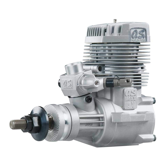
Page 6: Basic Engine Parts
BASIC ENGINE PARTS Glowplug Cylinder head Carburetor Type 61A (Type 61C For 95AX) Crankshaft Cover Plate Propeller washer Propeller nut Beam Mount Lock nut Crankcase Drive Hub -75AX is shown. Warning: BEFORE STARTING Make sure that the propeller is well Tools, accessories, etc. - Page 7 FUEL The 75AX and 95AX should be operated on a methanol Reminder! based fuel containing not less than 18% (volumetric) Model engine fuel is poisonous. Do not castor oil, or a top quality synthetic lubricant (or a allow it to come into contact with the eyes or mouth.
-
Page 8: Installation
LONG SOCKET WRENCH WITH PLUG GRIP TOOLS Recommended easy removal HEX Screwdriver replacement of the angled and recessed Necessary for engine installation. glowplug, the O.S.Long Socket Wrench 1.5mm, 2.5mm, 3.0mm incorporates a special grip. Phillips Screwdriver No.2, etc. End Wrenches 8mm, 12mm, 14mm, etc. - Page 9 How to fasten the mounting screws. ● Make sure that these mounting beams are Hardwood mounting beams accurately aligned and firmly integrated with Tighten second nut the airframe, reinforcing the adjacent 3mm steel nuts firmlydown onto first nut. structure to absorb vibration. Use 4mm or Tighten this nut first.
-
Page 10: Installation Of The Standard Accessories
INSTALLATION OF THE NEEDLE-VALVE EXTENSION The needle-valve supplied with this engine is STANDARD ACCESSORIES designed to incorporate an extension so that, when the engine is enclosed within the INSTALLING THE GLOWPLUG fuselage, the needle-valve may be adjusted from the outside. For this purpose a Needle Valve Extension Cable Set is supplied with the engine. -
Page 11: Fuel Tank Location
FUEL TANK LOCATION 75AX The Fuel line pickup weight should be 10mm Suggested fuel tank capacity is approx away from the back of the tank. 350cc. This will allow 10minute flights. Position the fuel tank so that approximately 95AX 1/3 of the tank height is above the center line Suggested fuel tank capacity is approx of the needlevalve. -
Page 12: Mixture Controls
MIXTURE CONTROLS Two mixture controls are provided on this Carburetor. Needle Valve The Needle Valve When set to produce maximum power at full throttle, this establishes the basic fuel/air Mixture Control Valve mixture strength. The correct mixture is then maintained by the carburetor's built-in Mixture Control Valve on the carburetor is set automatic mixture control system to cover at basic position ( a little on the rich side) at the... -
Page 13: Starting
STARTING Be sure to use an electric starter to Element glows when energized. start the engine. Pliers Never fail to check the tightness of screws and nuts, especially engine mounting and moving parts (e.g. throttle lever). Replace the plug when the element does not glow or is burnt out. - Page 14 Attention : How to stop the engine Do not choke the carburetor air intake when Pull down the throttle lever and trim lever on applying the starter. This could cause an the transmitter fully. excessive amount of fuel to be drawn into the Note: cylinder which may initiate a hydraulic lock and Make sure that the throttle linkage is set so...
- Page 15 Optimum needle setting(1) During subsequent flights, the needle-valve can be gradually closed to give more power. Slowly advance the throttle to its fully open However, if the engine shows signs of position, then gradually close the needle-valve running too lean, the next flight should be until the exhaust note begins to change.
-
Page 16: Mixture Control Valve Adjustment
MIXTURE CONTROL VALVE ADJUSTMENT With the engine running, close the throttle and In this case, turn the Mixture Control Screw allow it to idle for about five seconds, then counter-clockwise 90 degrees to positively open the throttle fully. If, at this point, the enrich the idle mixture, then turn the screw engine is slow to pick up and produces an clockwise gradually until the engine regains full... -
Page 17: Realignment Of Mixture Control Valve
REALIGNMENT OF MIXTURE CONTROL VALVE SUBSEQUENT STARTING PROCEDURE course making carburetor Once the optimum needle-valve setting has adjustments, it is just possible that the Mixture been established (see page 29, Needle-valve Control Valve may be inadvertently screwed in adjustment diagram) the procedure for starting or out too far and thereby moved beyond its may be simplified as follows. -
Page 18: Trouble Shooting When The Engine Fails To Start
TROUBLE SHOOTING WHEN THE ENGINE FAILS TO START Four key points For quick, reliable starting, the following four conditions are required. 1 Good compression. 2 Adequate "glow" at glowplug. 3 Correct mixture. 4 Sufficient electric starter rotating speed. If the engine fails to start, or does not keep running after being started, check symptoms against the following chart and take necessary corrective action. -
Page 19: Care And Maintenance
CARE AND MAINTENANCE Install an in-line fuel filter between the tank and carburetor to prevent foreign matter in Please pay attention to the matters the tank from entering the carburetor. described below to ensure that your engine serves you well in regard to performance, Clean these filters periodically. - Page 21 61A CARBURETOR EXPLODED VIEW N.+M3x6 S.M3X3 N.+M3.5x6 Type of screw N...Round Head Screw S...Set Screw 61A CARBURETOR PARTS LIST Code No. Description 27881400 Throttle Lever Assembly 27482200 Carburetor Rotor 25781600 Mixture Control Valve Assembly 46066319 "O" Ring (L) (2pcs.) 22781800 "O"...
- Page 23 61C CARBURETOR EXPLODED VIEW N.+M3x6 S.M3X3 N.+M3.5x6 Type of screw N...Round Head Screw S...Set Screw 61C CARBURETOR PARTS LIST Code No. Description 22081408 Throttle Lever Assembly 29087200 Carburetor Rotor 29181620 Mixture Control Valve Assembly 46066319 "O" Ring (L) (2pcs.) 22781800 "O"...
-
Page 24: O.s. Genuine Parts & Accessories
O.S. GENUINE PARTS & ACCESSORIES SILENCER EXTENSION O.S.GLOW PLUG RADIAL MOTOR MOUNT ADAPTORS No.7 (71905200) (71607100) Width Screw hole pitch 14.5mm 42.0mm (26625340) No.8 Long (71608001) 35.0mm 42.0mm (26625500) No.10 (Former A5) (71605100) NON-BUBBLE BLIND NUT NON-BUBBLE SUPER FILTER WEIGHT WEIGHT ( L ) (72403050) -
Page 25: Three View Drawing
75AX THREE VIEW DRAWING 105.4 SPECIFICATIONS Displacement 12.29 cc / 0.75 cu.in. Bore 25.8 mm / 1.016 in. Stroke 23.5 mm / 0.925 in. Power output at recommended R.P.M. range 1.5 ps / 1.52 hp / 10,000 r.p.m. Recommended R.P.M. range 2,000-11,000 r.p.m. -
Page 26: Memo
MEMO 6-15 3-Chome Imagawa Higashisumiyoshi-ku Osaka 546-0003, Japan TEL. (06) 6702-0225 URL : http://www.os-engines.co.jp FAX. (06) 6704-2722 60092190 061102 Copyright 2009 by O.S.Engines Mfg. Co., Ltd. All rights reserved. Printed in Japan.
Need help?
Do you have a question about the MAX-75AX and is the answer not in the manual?
Questions and answers
mounting dimentions
The mounting dimensions for the O.S. Engine MAX-75AX are:
- Length: 130.2 mm
- Width between mounting holes: 42 mm
- Hole spacing (front to back): 66.6 mm
- Hole size: UNF 5/16-24
- Distance between crankshaft center and mounting surface: 49 mm
- Distance from crankshaft center to top of engine: 54.1 mm
- Other dimensions include various offsets and component sizes such as 24 mm, 25 mm, 27.9 mm, and 35.7 mm.
This answer is automatically generated