
Related Manuals for PiXORD PB670


Summary of Contents for PiXORD PB670
- Page 1 H.264 Series Fish-Eye Compact Network Camera PB670 / PB670E User’s Manual Rev. 1.03 Released Date: 07/05/2012...
-
Page 2: Table Of Contents
Table of Contents Revision History ........................2 Notices ..........................3 Introduction .......................... 5 Installation ..........................6 Using the Web UI ....................... 14 1. Live View ........................ 15 2. Video ........................18 General ........................ 18 Advanced ......................20 3. Camera ........................21 General ........................ -
Page 3: Revision History
Revision History Version Description Author 1.01 Original document Anthony 1.02 Modify the GPIO picture Eric_Y 1.03 Change Wall 720P Mount SamKao... -
Page 4: Notices
Notices This user manual is intended for administrators and users of the PB670 Series Network Camera, including instructions for using and managing the camera on your network. The use of surveillance devices may be prohibited by law in your country. It is the user’s responsibility to ensure that the operation of such devices is legal before installing this unit for its intended use. - Page 5 PiXORD is not responsible or liable for the resale of its products with statements different from or beyond the specification/parameters stated by PiXORD. Customers are responsible for their applications using PiXORD products.
-
Page 6: Introduction
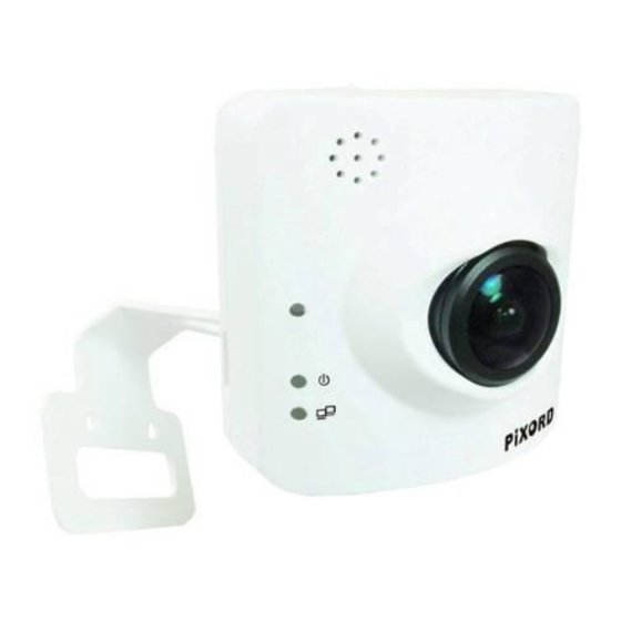
Introduction PB670 is a Fish-Eye Network Camera; it is featured with superior H.264-AVC performance and rich functions. Fish-Eye Camera includes a fish-eye lens for 360° wide angle view without blind spot. Thus Fish-Eye Camera is very suitable to view a wide area with single camera such as hallway, store, office, and etc. -
Page 7: Installation
Installation 1. Hardware Connection 1. Prepare a PC with Ethernet link to the network 2. Connect LAN port (RJ45) of the camera to a network switch/hub 3. Connect power jack / POE ; POE support only for PB670E 4. Ensure the power adaptor specification matching the power system (110V or 220V) and connect the adaptor to the outlet 5. -
Page 8: Software Installation
2. Software Installation The following software is necessary for the proper display and use of the Fish-eye camera from the Web site. The software will be taken from the Software CD. IP Installer The IP Installer is used to locate and configure network cameras and video servers on the LAN. This utility is useful for conveniently configuring and finding the network settings of the device. -
Page 9: Network Configuration
PC must be in the same subnet. For more information about subnets, please consult your network administrator. Using IP Installer to Assign an IP Address to PB670 Once IP Installer has been successfully installed on the PC, double click the IP Installer icon on the desktop, Click the [Device Search] to search the device in the LAN. - Page 10 From the list, select the device with the MAC address that corresponds to the camera that is to be configured. The MAC address is identical to the S/N of unit. (S/N = Serial Number). Double click the select item to open the property page or right click the item to select the [Single Device Setting].
- Page 11 After filling in the properties, click [Set] button to complete the configuration settings. Click the [Batch Device Setting] to set several devices.
- Page 12 Supported languages: Traditional Chinese, English and Spanish.
- Page 13 Open the Web-based UI of the Selected camera To access the web-based UI of the selected unit, run the View > Open web on the menu bar. For first-time use, there will be a prompt to install the ActiveX control. Confirm the installation as it is required to view the video stream and some operations.
- Page 14 If the device has been configured correctly, the default web browser will open to the home page of the selected device. Verify and Complete the Installation from Your Browser When browsing the home page at the first time with the Microsoft Internet Explorer , you must temporarily lower your security settings to perform a one-time-only installation of the ActiveX component onto your workstation, as described below:...
-
Page 15: Using The Web Ui
Using the Web UI Start your web browser and enter the URL or IP address in the address field. The home page of the camera is now displayed. -
Page 16: Live View
1. Live View IP address of the Video Resolution Frame camera format Rate rate Button Description Click this button to access general/advance camera settings. Choose a language for the user interface. Languages options are English, traditional Chinese and simplify Chinese. Click this button to display different views. - Page 17 Button Description Click this button to switch to full screen mode. Click this button to listen the audio input from local end. Click this button to talk to people around the Network Camera. Click this button to record video clips to your computer. Click this button to capture and save still images.
- Page 18 Configuration Pages List Video General Advanced Camera General Advanced Event Event Server Motion Detection I/O ports Event Configuration Schedule General Storage Network General Advanced SMTP (E-mail) DDNS System ...
-
Page 19: Video
The PTZ function will display in quad with source view, double with source view, double view of wall mount and wall mount 720P, triple view of wall mount and wall mount 720P. icon Click the PTZ , the web will pop up the control panel to control e-PTZ function of PB670. Double with source view PTZ control panel:... - Page 20 1. Step: Set the speed of Pan function. (1~10) 2. Pan Arrow: Click this button to control Pan. 3. Move the control panel. 4. Close the control panel. 5. Zoom: Digital zoom in/out.(1~10) 6. Preset Point: List of preset points. (1~16) Triple &...
-
Page 21: Advanced
Advanced Stream 1 Setting: RTSP Path: It is the stream ID used for RTSP client streaming connection, such as VLC player. (default v00) Resolution: 1600x1200, 800x600, 640x480. Video Mode: Choose between variable bit rate (VBR) and constant bit rate (CBR) <1>: VBR->... -
Page 22: Camera
3. Camera General... - Page 23 Camera General Setting: Brightness: The luminance of image view Hue: Pure color described by its name, such as red, green or blue. Saturation: Intensity of a specific color The 3 correlates are referring image appearance in terms of color/vision. They are adjustable from this page.
- Page 24 White balance: Adjust compensation for different environments in terms of light source. Exposure: Anti-flicker setting for image sensor to fit the frequency of light (power) source. For instance, the power frequency is 50Hz for most European countries, while 60Hz is typical for US. This setting is therefore regionally different.
- Page 25 layout to choose; original view, broad view, quad with source view and triple view. 1: Original view 2: Board view...
- Page 26 3: Quid with source view 4: Triple view...
- Page 27 Ceiling Mount: Choose the ceiling mount, and go back to live view. There are 2 kinds of video layout to choose; original view, and quad view. 1: Original view 2: Quad view...
- Page 28 Wall 720P Mount: Choose the wall 720P mount type, and go back to Live view. There are 3 kinds of n video layout to choose; broad view, double view, double with source view. 1: Board view 2: Double view 3: Double with source view...
-
Page 29: Event
4. Event... -
Page 30: Event Server
Event Server Click on the [Add FTP] to expand the FTP server setting. FTP Server: Name: Enter a name for the FTP setting. Network Address: Enter the network address of the FTP server. Upload Path: Choose the path for uploading events. ... - Page 31 Click on the [Add HTTP] to expand HTTP server setting. HTTP Server: Name: Enter a name for the HTTP setting. URL: Enter the URL of the HTTP server. Username / Password: Input the username and password of the HTTP. Click [Remove] to delete selected event servers (circled in blue)
-
Page 32: Motion Detection
Motion Detection To add a motion detection area: 1. Click [Add] to set up a detection area. (Set up panel will be expanded) - Page 33 2. Enter a name to this window area. 3. Select the trigger level and sensitivity for this detection window. (0~100, low~high) 4. Select color for detection window. 5. The draw detection window is displayed on the image.
-
Page 34: I/O Ports
6. Once everything is done, click [Save] to save the configuration made. Configured detection window will be displayed in motion detection list. (Circled in blue) Note: 1. Maximum number of detection window is 10. I/O Ports This model supports 1 photo-coupled relay inputs and 1 relay outputs, referring to “I/O Terminal Connectors”... -
Page 35: Event Configuration
Event Configuration The Event Configuration is to assign the actions responding to the specified events (Trigger Conditions). The table lists the configured events. Click “Add…” or choose an event from the list to expend the panel for detail configurations. “Remove” is to delete a selected event. 1. -
Page 36: Schedule
5. Schedule General Define the day (specified by days of a week) and time (specified by each single hour), so that the camera will be recorded during the scheduled period. (Note: Only video data will be recorded.) User can select which video stream to record. -
Page 37: Storage
Storage The storage information shows disk size info, type and status. The warning message (red text) shows when recording is on process; SD card can not be removed during the recording process. The “Browse” button allows viewing the list of recorded files, and then the web page will be redirect to the root path of the SD storage (if one is inserted). - Page 38 The recorded files are named in date_time format, and the extension file name is “.h264”. While file is in h264 raw format, it can be played in VLC player. (Note: The recorded file only includes video, no audio information.) ※ Noted~!! Please into the SD memory card in the slot before start the machine~!!!
-
Page 39: Network
6. Network General The device IP configuration includes DHCP and Static IP setting. “Enable ARP/Ping” enable device to accept ARP or ping packets from the network. Disabling this option provides extra security from intentional ping. -
Page 40: Advanced
Advanced Enable or configure other network functions. NTP: Configure a NTP (Network Time Protocol) server, so that the date and time of the device system can be synchronized with a specified Time Server. This configuration is provided for one of the potions of system date/time adjustment. -
Page 41: Smtp (E-Mail)
SMTP (E-Mail) Configure an email host in the device, and it will send a email on behalf of the configured email account in a circumstance, like sending an email notice to a specified mail address (Event Configuration). Sender: Complete the Mail Server, Server Port, Authentication information (if required) and the email address of sender. -
Page 42: Ddns
DDNS Dynamic DNS(DDNS) configuration: The network device can be assigned and accessed with a host name instead of IP address by registering this service (Internet access required). Host Name: Assigned name will be used for access to the device User Name/Password: Account authentication for logging to this service Update Time: Periodically, the device updates its access information to sever in the configured time. -
Page 43: System
7. System Information A list of System and Network configurations... -
Page 44: User
User User setting is to set up the accessing network camera for viewing and configuring the device. Enabling anonymous login allows guest users to access the Web User interface without any authentication. Note: For configuration settings an Administrator username and password is still required. The default username and password is admin/admin respectively. -
Page 45: Date & Time
Date & Time System date/time configuration. Options of synchronizing with PC and NTP server are provided for automatic adjustment. -
Page 46: Server Maintenance
Server Maintenance This page provides for system maintenance; reboot and load default settings, as well as the function of launching upgrade process, backup/restore user settings and language defines. -
Page 47: Log Service
Log Service Most system operations and / or process will be kept in a log system. The link provides the review of these records. -
Page 48: Customize
8. Customize This page provides the function of adjusting the look of live view page. There are two types of layout settings; use default look or use custom settings. Use Default Look: The default layout of live/configuration pages Use Defined Links: Web link(s) will be presented on the live page when enabled. It can be a link to another IP camera for instance, or other preferred web link. - Page 49 Use Custom Settings: The allowed modifications are change of Background / Text Color, Background picture, Title, Description, Logo and etc.
-
Page 50: Faq
I/O Terminal Connector - Pin Assignment Function Description DO_NO Digital output implementation; Pin7 to COM (Pin6) is a Photo-coupled relay on Normal Open status. External device can directly connect to the terminals. DO__COM However the current that will go through the 2 nodes must not exceed 130mA. An external “Relay”... -
Page 51: Restore Factory Default
Restore Factory Default Reset Button To restore factory default, please follow the steps: Unplug the power jack to turn off the power of the camera. Insert a pin into the reset hole as circled with red in the below figures. Sense a button and keep it pressed until instructed to release. -
Page 52: Upgrade Device Firmware
Upgrade device firmware Firmware upgrade process should be done via the web configuration; Setup -> Server Maintenance -> Firmware Upgrade. Before the process, read the instructions and release notes coming with each new released version. For the steps, Check and retrieve the latest firmware bin file. Disconnect all clients (e.g.
Need help?
Do you have a question about the PB670 and is the answer not in the manual?
Questions and answers