Table of Contents
Advertisement
Quick Links
Advertisement
Table of Contents

Subscribe to Our Youtube Channel
Related Manuals for PiXORD P-465


Summary of Contents for PiXORD P-465
- Page 1 Pixord MPEG-4 Network Dome Camera P-465 User’s Manual Date: 04/09/2008...
-
Page 2: Table Of Contents
Content 1. Preface................6 2. Features ................ 7 3. Warning & Cautions ............8 4. Structure Element............10 5. Fast Dome Camera Set Up..........11 5. 1 RS-485 Protocol Switch Setting ..............11 5. 2 RS-485 Communication Mode Selection..........12 5.3 Transmission Speed Setting ...............12 5.4 Protocol Setting.....................12 5. - Page 3 10.4 Digital Zoom Selection................30 10.5 On/Off the Audio and Rotate the Video...........30 Select the Channel....................30 On/Off the Audio .....................30 Rotate the Video....................30 10.6 Video and Audio Recording ..............31 10.7 Video Conference..................32 Control the Video in Location Window ............32 Setting for Video Record..................33 Select the Remote Device ................33 Manually Setup Additional Camera..............34 11.
- Page 4 User Settings ....................54 11.10 Firmware Upgrade ...................55 11.11 Configuration of Event ................56 General......................56 Set Motion Area ....................57 Set Email and FTP ...................58 12. Operation ..............59 12.1 Initial Power Up Inspection ...............59 12.2 Manual Operation (Pan/Tilt Control)............59 12.3 Fast Dome Selection..................60 12.4 Zoom Lens Control..................60 12.5 Focus Control....................60 12.6 Iris Control ....................61...
- Page 5 14.12 Restore Factory Defaults ................92 14.13 Schedule Setup Menu ................94 14.14 Alarm Input Schedule Setting Menu............94 14.15 Start Auto Options Menu .................95 14.16 Daylight Saving Time Menu..............97 14.17 Display System Information..............98 14.18 Camera Reset...................99 15. Specification ............100 15.1 Operational ....................100 15.2 Camera ......................100 15.3 Optical Lens ....................101 15.4 Electrical ....................101...
-
Page 6: Preface
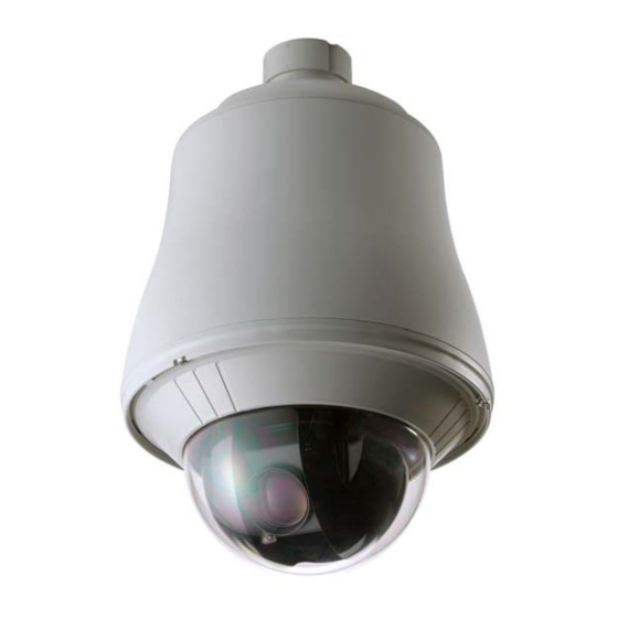
1. Preface P465 is an outdoor fast dome cameras with high resolution of 520 TV lines offer significant enhancement and refinements to bring you the most innovative surveillance solutions. P465 is the leading product in the industry offering the most advanced features such as 35X optical zoom lens, auto white balance mode selection, IR cut filter function, auto focus control, auto iris control etc. -
Page 7: Features
2. Features 35X Auto Focus Lens: Build-in 35X optical zoom lens with focal length 3.6~126mm 520 Horizontal TV lines Automatic / Manual Iris Control Preset ID / Name Preset Background Environment File Private Mask 360 degrees continuous rotation Up to 128 programmable preset positions Preset positions auto scanning High speed rotation and tilt, speed range varies from 0.15∘/ sec ~ 360∘/ sec 180 degrees Horizontal Instant Flip... -
Page 8: Warning & Cautions
3. Warning & Cautions Please read the manual before attempting installation or operation Please be aware to the warnings and cautions notice. Don’t use any chemical detergent to clean the machine surfaces, use a damp cotton cloth only. Regularly clean the dome cover to assure proper focus ability. Please install the fast dome in a dry area, water and high humidity may cause damage internal parts. - Page 9 Unusual occurrence 18. Warning: Do not try to repair the equipment. Only a qualified technician may disassemble and repair the equipment. Shut off the power before disassemble the equipment and don’t put power on unless the case is completely assembled.
-
Page 10: Structure Element
4. Structure Element 1. Dome Cover 2. Camera Case 3. Upper Base 4. Power In Jack (AC100~240V) 5. Power In Jack (AC24V) 6. RS-485 In/Out Terminal 7. Video Out Jack 8. Alarm In/Out connector... -
Page 11: Fast Dome Camera Set Up
5. Fast Dome Camera Set Up 5. 1 RS-485 Protocol Switch Setting Explanation of DIP Switch Setting: RS-485 In-TML RES : RS-485 IN Terminal Resistor ON/OFF RS-485 OUT-TML RES : RS-485 OUT Terminal Resistor ON/OFF HALF/FULL :2 wiring system (HALF duplex) or 4 wiring system (Full duplex) BAUD SEL 1 :Transmission speed selection 1 BAUD SEL 2... -
Page 12: Communication Mode Selection
5. 2 RS-485 Communication Mode Selection DIP SWITCH 2 wiring system (HALF duplex) 4 wiring system (FULL duplex) Communication Mode of HALF: Most of systems use this mode because of low-cost and easy setup, but this mode can’t receive and transmit data simultaneously. Communication Mode of FULL: This Mode can receive and transmit data simultaneously. -
Page 13: Fast Dome Id Address Setting Refer Chart
5.6 Fast Dome ID Address Setting Refer Chart Up to 64 fast dome cameras can be serial linking in one system. Therefore each dome is addressing by ID switch located at the base of the fast dome. When select MLP 1, camera ID setting as followings:... - Page 14 Fast Dome Connection Jack and Cable Requirement AC 100~240V Power Cable AC 24V Power Cable Recommend Cable: Accessory Connector Information Assemble the Cable with the Accessory Connector Strip back the cable jacket approx. 3mm and separate the individual conductors.
- Page 15 Prepare the individual conductors for clamping. After clamping the contacts, push them into the proper holes in the accessory connector of this camera until they snap in place. CAUTIONS: CONNECT THIS TO 24V AC CLASS 2 POWER SUPPLY ONLY RS-485 In/Out Terminal RS-485 Input (TXDO+, TXDO-) to receive signal from keyboard, matrix, DVR or multiplexer through twisted pair cable.
-
Page 16: Installation
6. Installation Step 2 Step 1 Separate bracket from base of bracket Step 2 Fix base of bracket on the wall Step 3 Attach camera to bracket... - Page 17 Step 4 Fast Dome Camera Setting Step 5 Connect Jack...
- Page 18 Step 6 Fix bracket and outdoor fast dome camera with base...
-
Page 19: System Configuration
7. System Configuration P465 is suitable for a wide range of surveillance applications. The system can be single fast dome with one keyboard or encompassing as 64 domes with comprehensive matrix switching, PC control and even Digital Video Recording. Such flexibility means future expansion is easily facilitated. 7.1 Fast Dome and Keyboard Single dome configuration: One fast dome camera connects to one PIH-800II or PIH-931D/932T. - Page 20 Multiple Domes means that more than one fast dome is linked in the system. Each dome connects to next dome forming a serial linking. Each dome has an individual ID dip switch, which allows the keyboard to identify each fast dome and make command. Sometimes it is more convenient to wire a telemetry system in star configuration rather than daisy chain.
-
Page 21: Fast Dome, Matrix And Keyboard
7.2 Fast Dome, Matrix and Keyboard Matrix system is designed to process multiple video system and video switching. Its central process unit (CPU) can manage multiple video signals simultaneously and control other linking system, such as fast dome or PIH-820III telemetry receiver. All telemetry remote control and signal transmissions are through twisted pair. -
Page 22: Fast Dome With Pc Control
RS-485 Connection Between Keyboard and Matrix TXDI+ of 1 keyboard RS-485 IN connects to 1 pin TXD+ of matrix’s keyboard jack. TXDI- of 1 keyboard RS-485 IN connects to 2 pin TXD- of matrix’s keyboard jack. 7.3 Fast Dome with PC Control PC telemetry remote controls fast dome with standard RS-485 data format (Baud Rate 9600bps). -
Page 23: Fast Dome, Dvr And Keyboard
RS-485 Connection Between Fast Dome and Conversion Interface TXD+ of conversion interface RS-485 jack connects to TXDI+ of 1 fast dome and connect TXD- to TXDI- Linking 2 Fast Dome TXDO+ of 1 dome RS-485 jack connects to TXDI+ of 2 dome to TXDO- of 1 dome to TXDI- of 2 dome. -
Page 24: Software Installation
8. Software Installation With the exception of the Macromedia Flash Player all the software that is necessary for the proper display and use of the device is available on the included CD or from the website. For the following installation procedures it is assumed that all installation media will be taken from the CD. IP Installer The IP Installer is used to locate and configure network cameras and video servers on the LAN. -
Page 25: Network Configuration
Assigning IP address to Camera Once IP Installer has been successfully installed on the computer, double click the IP Installer icon on the desktop, or select it from Start > Programs > PiXORD Corporation > IP Installer > IP Installer. - Page 26 From the list, select the device with the MAC Address that corresponds to the device that is to be configured. The MAC Address is identical to the unit’s S/N (Serial Number). Double click the item to open the Property Page dialog box for the selected device or click the menu bar View >...
- Page 27 Verify and Complete the Installation from Your Browser Start your browser and enter the IP Address of your NDC in the Address field. The camera can support Microsoft Internet Explorer and Netscape . But the voice feature can only be run under Microsoft Internet Explorer When browsing the Home Page at the first time with the Microsoft Internet Explorer , you must temporarily lower your security settings to perform a one-time-only installation of the ActiveX...
-
Page 28: Usage Of Web-Based User Interface
10. Usage of Web-based User Interface Start your Web browser and enter the IP Address of your Camera in the Address field. The Home page of the camera is now displayed. The Web UI can present up to 4 video source indicating 4 video channels. Each channel can be shown individually or in one of 4 split windows. -
Page 29: Video Channel Selection
10.2 Video Channel Selection The Video Channel allows the users to choose viewing 1 channel at a time or 4 channels at the same time. CH1 displays the video stream of the camera. CH2~4 display the video stream of the IP Camera or Video Server that connected the device via network. -
Page 30: Digital Zoom Selection
To pan/tilt/zoom the external video sources CH2~CH4, click on [CH2~4 PTZ Control] button to open a new window. Select the channel in this window to display the PTZ control panel for operation. 10.4 Digital Zoom Selection The Digital Zoom enable user to select the digital size for the channels. -
Page 31: Video And Audio Recording
To stop recording, select the channel from the tab and then click [Manual Recording] button again, the “REC” message will disappear and the recording is stopped. By default, the recorded file will be saved in a folder named C:\PiXORD\Recfile\pppp\CHx\ ♦... -
Page 32: Video Conference
10.7 Video Conference Click [Video Conference] to open the conference page. Rotate this video for Click this button to open the Configuration page viewing Click this button backs to On/Off the audio of this the Home page video stream Camera Setting Record Stop... -
Page 33: Setting For Video Record
Speed: Click on the UP/Down arrows and select the speed of the Pan and Tilt movements. Values run from 1 to 7. Being 1 the slowest and 7 the fastest Manual Pan/Tilt: Click on the 4-directions button to move the camera to that direction. Click on the rectangle button to stop the movement. -
Page 34: Manually Setup Additional Camera
Manually Setup Additional Camera This feature allows the user to temporary set an additional video source for the remote device. Note: This camera will be removed after leaving or closing the Web page. Click on [Camera Manual Setting] button on the Remote window, and configure the following settings: IP address: Enter a valid IP address from an IP Camera or Video Server. -
Page 35: Configuration Of Web-Based User Interface
11. Configuration of Web-Based User Interface The Configurations of the camerras are presented as links in the margin of the Configuration Page. Simply click the relevant link for the settings you want to configure. 11.1 Configuration Preview A/V Settings Functions Description General Set the parameters of video and... -
Page 36: System
System Functions Description System Information Set various information about the name of the device and the language type, etc. Time Configuration Set the Date and Time. User Add and delete users and passwords. Firmware Upgrade Browse firmware location to upgrading Event Functions Description... -
Page 37: Configuration Of A/V Setting
11.2 Configuration of A/V Setting Basic A/V Settings Audio: Enables and Disables the audio stream. Resolution There are 3 different resolutions to choose from: ♦ D1: 720x480 NTSC / 720x576 PAL (DVD Standard resolution) ♦ SIF: 352x240 NTSC / 352x288 PAL ♦... - Page 38 If you are planning on using the device on an Internet connection, it is recommended that you select a constant bitrate that corresponds to your actual upload speed. It is also recommended that you modify the frame rate and resolution as well, otherwise the video stream may become blocky or otherwise distorted.
-
Page 39: Advanced A/V Settings
Advanced A/V Settings Interlacing There are 2 modes available: Interlaced or Progressive. Interlaced mode is a storage mode. An interlaced video stream contains fields rather than frames, with each field containing half of the lines of a frame. A progressive video stream consists of only full frames. Interlaced video streams can bring a lower bitrate but may cause lower quality. -
Page 40: Image Adjustment
Image Adjustment Contrast, Brightness, Hue and Saturation: The value can be adjusted from -100 to 100. Rotation: Rotation degrees run from 0 to 270 degrees for a permanent digital position. ♦ 0: 0 degree ♦ 1: 90 degrees ♦ 2: 180 degrees ♦... -
Page 41: Setting External Sources
11.3 Setting External Sources Video Select: Select the channel this external source will be displayed. IP Address: Enter a valid IP address from an IP Camera or Video Server. Http Port: Enter the port number used for the IP address for network connection. Video Type: Select MJPEG or MPEG4. -
Page 42: Ptz Settings
11.4 PTZ Settings Setting ID for NDC Managing Preset Points Select an ID number to match the ID Managing the Preset Points for address set by the dome camera. quick view and auto pan. Changing Lens Speed Switching the lens speed between default setting and manual setting. -
Page 43: Operating The Dome Camera
Operating the Dome Camera To control the dome camera for viewing, follow the description shown on below: Pan / Tilt the Dome Camera To control the pan and tilt movement of the dome camera simply click on the buttons: To pan or tilt, just click on the 8-directions buttons for the desired direction. -
Page 44: Preset Point Setting
Preset Point Setting There are 128 individual preset points. Each preset stores the exact position of the camera and automatic pan, tilt, zoom, focus and iris setting. Once the data is set, the preset can be recalled for viewing, or the presets can be set for auto pan. Note: Only the first 16 preset points of the device can be set to auto pan mode and first 6 preset points are corresponding with the 6 alarm inputs. - Page 45 Set preset speed. The speed the dome travels to that preset point can be adjusted between 10 to 250 seconds. The presets Group 1 ~ 4 (First 16 preset points) can be entered a name for identify. Just fill the text string into the Position Name field.
-
Page 46: Setting Day / Night Mode
11.5 Setting Day / Night Mode There are 3 modes can be selected to set the IR Cut Filter for different environment. Click IR filter Swap to switch the modes. ICR ON (ICR IN): IR Cut Filter is ON and always produces constant color image. ICR OFF (ICR OUT): IR Cut Filter is OFF and always produce monochrome image. -
Page 47: On Screen Display
11.7 On Screen Display On Screen Display: Select Enable/Disable for displaying the text over the video. OSD Text: Fill in the text string to display. The valid characters are a – z, A – Z, 0 – 9, !, @, #, $, %, &, *, ( and ). -
Page 48: Configuration Of Network Setting
11.8 Configuration of Network Setting General Settings MAC Address: Display MAC address information for this device. It is read only information. IP Address: IP address of the device. Subnet Mask: Subnet mask of your LAN. Note that the IP Address above and Gateway IP Address below should be in the same subnet. -
Page 49: Dynamic Dns Settings
Then camera automatically “update” to the DDNS server by a fix frequency, so even the IP is changed by ISP, the DDNS server still could get and update internal database. Then, once users access from Internet with its register name, e.g. if registering with server name “demo” to DDNS server “ddns.pixord.com”, the camera could be accessed by http://demo.ddns.pixord.com. - Page 50 Device Name: Specify server name. This name setting also used by the DDNS service to recognize each server. E.g. if configure name as “user” to DDNS address “ddns.pixord.com”, then this NDC can be accessed by URL http://user.ddns.pixord.com after register to the DDNS server.
- Page 51 Dynamic Settings 2 Dynamic DNS Settings: Select [Enable] if you wish to activate the DDNS service through DynDns. DDNS Host Name: Specify server name that you have registered in http://www.dyndns.org E.g. if the registered name is “user” to DynDns, then this NDC can be accessed by URL http://user.dyndns.org Account ID: Enter the username provided by DynDns.
-
Page 52: Configuration Of System
11.9 Configuration of System System Information MAC Address: Display MAC address information for this device. It’s read only. Language: Alternative language option. User may change the language of web contents for different application. Description: Useful as an administrative identifier. Does not affect the operation of the device. Location: Useful for identifying the position of the device. -
Page 53: Time Configuration
Time Configuration Time Mode ♦ Synchronize with NTP server: Synchronize the current time with a NTP server over Internet. ♦ Set Manually: Manually set the time. Click on [Synchronize with computer time] button to set the date/time of the camera as your PC’s, or Set the date and time by clicking on the arrow button beside each field and select the value from the pull-down list. -
Page 54: User Settings
User Settings Add User To add a user, enter the user name and password in the respective fields. Select [Group] and [Permission] of each channel, and then click on [Add User] button. The user in Administrator group has all permission to operate the device. The user in General group can be configured to have limited permission to operate the device. -
Page 55: Firmware Upgrade
11.10 Firmware Upgrade To upgrade firmware, first browse the folder where you have placed the newest firmware. After finding the path then click on “Update” to upgrade the device. -
Page 56: Configuration Of Event
11.11 Configuration of Event General Trigger System provides “GPIN” and “Motion Detection” for event detection. GPIN & GPIO Input Status: They are auto detected and display the status. Motion Detection: Make a checkmark on this option to start detect the motion area. See next segment to set the motion area. -
Page 57: Set Motion Area
Set Motion Area The “Motion Detection” checkbox (Configuration>Event>General>Trigger) must be enabled when use this function. Use mouse to drag out a detection area on the video. Left-click the area and drag the corner to change the size. Right-click the area and select “Property”. Check “Enable”, click “OK”... -
Page 58: Set Email And Ftp
Set Email and FTP E-mail Setting The “Mail Image” checkbox (Configuration>Event>General>Action) must be enabled when use this function. Mail From: Enter the mail address of the mail sender. Receipt To: Enter the mail address of the mail receiver. Mail Server: Enter the mail server name or IP address. Authorization: Disable or enable the security for mail authorization. -
Page 59: Operation
12. Operation 12.1 Initial Power Up Inspection After the power is first applied to a dome it will perform a self-test procedure. This calibrates and checks the basic functions of the dome, control is not possible during this self-test period. Once the camera has stopped moving, it will then be ready to control. -
Page 60: Fast Dome Selection
12.3 Fast Dome Selection To call out a dome controlling or setting To Select 1 Fast Dome Push followed by To select 64 Fast Dome Push key then followed by Note: When matrix system is used, select monitor before camera selection. Please refer to matrix system user manual. -
Page 61: Iris Control
12.6 Iris Control The purpose of this iris control is to adjust brightness on target. It can be set as Auto Iris or Manual Iris. Iris Open Push key, to open the iris and brighten the picture. Iris will stop when the key is released. - Page 62 Selecting Preset Position Push key followed by key, confirming that first preset position selected. EX. To select the 1 preset position: keys. To select the 128 preset position: keys. Joystick Control Move the joystick to bring the camera to the desired view position. Adjusting Lens ZOOM IN/OUT, FOCUS NEAR/FAR/AUTO and IRIS O/C/AUTO keys.
-
Page 63: Recalling Preset Positions
Storing Preset Data Once the above steps have been completed, the information must be stored or it will not be memorized by the system. Push followed by key, two beeps will be heard confirming that data is stored. Note: For the first 16 presets on each dome, the above steps must be repeated. For presets 17~128 there is a default speed and dwell setting so steps 5 and 6 are not required. -
Page 64: Changing Preset Data
12.11 Changing Preset Data In order to change any preset position from the one stored, the dome must first be sent to that preset position. To change the 4 preset position of the Dome number 3, perform the following steps: Push to select Dome 3 Push... -
Page 65: Alarm Management
12.14 Alarm Management The 6 alarm inputs of each fast dome are corresponding with the first 6 preset positions. When an alarm signal is triggered, the dome will go to the relevant position at 360°/sec. Make sure the first 6 preset positions are set to desired alarm areas. -
Page 66: Alarm Output
12.15 Alarm Output Each fast dome has 1 alarm output. A dip switch can program the alarm output for NO (normally open) or NC (normally close), that can activate the linked devices. When alarm response mode is set to LOCK Mode: When the alarm is triggered, NC contact to Common will be open and NO contact to common will be close. -
Page 67: Setup Menu Tree
13. Setup Menu Tree... -
Page 69: Fast Dome Camera Function Setup
14. Fast Dome Camera Function Setup P465 (built-in 35X optical zoom lens with Hi-Resolution and Day & Night function) provide on-screen display (OSD) setup menu, all functions can be selected and set via OSD setup menu. 14.1 Setup Menu Display Press key on the keyboard to recall setup menu. -
Page 70: Display Setup
14.3 Display Setup Display Setup Menu Press key into Setup Menu. Push joystick down to select <DISPLAY SETUP> and then press key to display setup menu. Push joystick down to select <BACK> and then press key to go back or push joystick down to select <EXIT>... - Page 71 Date and Time Setting Push joystick down to select <DATE/TIME> and then push joystick left or right to make selection: OFF: No Date/Time on the monitor screen ON: Display Date/Time on the monitor screen. When selection is open and then press key, date/time will be set.
- Page 72 Pan/Tilt Angle Setting Push joystick down to select <PAN/TILT ANGLE> and then push joystick left or right to select pan/tilt setup: OFF: No Pan/Tilt Angle on the monitor screen ON: Pan/Tilt Angle on the monitor screen.
-
Page 73: Dome Setting
14.4 Dome Setting Press key into setup menu. Push joystick down to select <DOME SETTINGS> and then press key into dome setting menu. 14.5 Camera Setting Display the Camera Setting Menu After getting in dome setting menu, push joystick down to select <CAMERA> and then press key into camera setting menu. - Page 74 Auto: Keep performing auto focus function for object. Interval: Fix interval time (5 sec) performing auto focus function for object. Zoom Trigger: Auto focus function will be performed, when only this condition that camera zoom ratio is changed. Zoom Minimum Setting Push joystick down to select <ZOOM MIN>...
- Page 75 Auto Exposure: will automate to select shutter speed by brightness variation to exhibit image effect of high brightness area Press key into Auto Exposure Setting and then push joystick left or right to made selection. Manual Exposure: Can set a fixed shutter speed with iris to exhibit image effect. Press key into Manual Exposure Setting and then push joystick left or right to made selection...
- Page 76 White Balance Setting Push joystick down to select <WHITE BALANCE> and then push joystick left or right to select white balance mode. ATW: Auto Tracing White Balance, suitable for 2500~9500K color temperature environment. PUSH: Push mode, suitable for 2300~10000K color temperature environment. MWB: Manual White Balance, suitable for 2500~9500K color temperature environment.
- Page 77 SCHED: IR CUT FILTER switches automatically between Day mode and Night mode by schedule of time setting. When selection is <SCHED.> press key into ICR SCHEDULE Setting menu. Push joystick down to select <DAY-> NIGHT> and then press key into time setting.
- Page 78 Synchronization Mode Setting Push joystick down to select <SYNC MODE> and then push joystick left or right to select mode. INT: Use synchronization signal of internal camera. LL: Synchronize synchronization signal of camera and AC signal of external power. Select <LL> and press key into LL setup and then push joystick left or right to adjust LL phase.
-
Page 79: Pan/Tilt Setting Menu
Aperture Gain Setting Push joystick down to select <APERTURE GAIN> and then push joystick left or right to make selection (00~15). Mirror Setting Push joystick down to select <MIRROR> and then push joystick left or right to make selection (OFF or ON) Note: Image will be Left/Right reverse. - Page 80 Self Return Time Setting Push joystick down to select <SELF RETURN TIME> and then push joystick left or right to select return time. OFF: NO action 1~9: Delay time of return time setting is 1~90 min. Note: When keyboard control isn’t used, “Return Time” is also over, “Return Mode” function will be started.
- Page 81 Auto Scan Mode Setting Push joystick down to select <AUTO MODE> or <SELF RETURN MODE> and then push joystick left or right to select <AUTO> then press key into auto scan mode setting. Position of Auto Pan Setting Push joystick down to select <EDIT POSITION> and then press into setting menu.
- Page 82 Patrol Mode Setting Push joystick down to select <AUTO MODE> or <SELF RETURN MODE> and then push joystick left or right to select <PATROL> then press key into patrol mode setting. Patrol Learn Setting Push joystick down to select <LEARN> and then press key into setting menu.
-
Page 83: Preset Function Setting Menu
14.7 Preset Function Setting Menu Display the Preset Setting Menu After getting in dome setting menu, push joystick down to select <PRESETS> and then press key into presets setting menu. Select Preset Numbers Select number by PRESET NUMBER: Push joystick down to select <PRESET NUMBER> then push joystick left or right to select preset number (1~128) Select number by PRESET MAP: Push joystick down to select <PRESET MAP>... - Page 84 Edit Position Setting Push joystick down to select <EDIT POSITION> then press key into preset position setting. Push joystick left, right, up or down to start position and then press to adjust zoom, focus, iris then press key to confirm. Edit ID Setting Push joystick down to select <EDIT ID>...
- Page 85 Push joystick down to <OK> and press key to exit. Select another preset on the preset menu and get into preset ID setting. Then push joystick down to “EDIT AREA” and press key for copy. At this time edit area will show preset ID that was copied.
-
Page 86: Tour Function Setting Menu
Dwell Time Setting Push joystick down to select <DWELL TIME> and then push joystick left or right to select needful dwell time (1~255 sec) Note: Only preset No.1~16 can set dwell time, because group of auto pan can only edit preset No 1~16. - Page 87 key to exit. Cancel Tour Push joystick down to select <CLEAR ABOVE NUMBER> then press key to cancel tour. Dwell Time Setting Push joystick down to select <DWELL TIME> then push joystick left or right to select dwell time of tour (1~255 sec) Note: When Self Return Mode or Auto Mode is Tour, dwell time of Auto Pan will be dwell time setting of tour.
-
Page 88: Privacy Zones Setting Menu
14.9 Privacy Zones Setting Menu Display the Privacy Zones Setting Menu After getting in dome setting menu, push joystick down to select <PRIVACY ZONES> and press key into privacy zones setting menu. Privacy Zones Number Setting Push joystick down to select <NUMBER> then push joystick left or right to select number (1~8) Note: If privacy zone is “OFF”, privacy zones setting won’t be edited. -
Page 89: Alarm Setting Menu
Cancel Privacy Zone Mask Push joystick down to select <CLEAR> then push joystick left or right to select <ABOVE NUM.> or <ALL>. Then press key to confirm. ABOVE NUM>: Only cancel parameter of allotted privacy zone. ALL: Cancel parameters of all privacy zone (1~8) 14.10 Alarm Setting Menu Display the Alarm Setting Menu After getting in dome setting menu, push joystick down to select <ALARMS>... -
Page 90: Password Function Menu
Event Mode Setting Push joystick down to select <EVENT MODE> then push joystick left or right to select <LOCK> or <RELEASE> LOCK mode: When multi-alarm is triggered, camera will lock event point of last alarm. RELEASE mode: When multi-alarm is triggered, camera will do sequence of alarm event point each 5 sec until event return time stop. - Page 91 Push joystick down to select <OK> then press key to confirm and back to password function menu or push joystick down to select <CANCEL> then press key to cancel password. These numbers of EDIT column will be reset to “1111”. Note: When edit password setting and camera recording function are simultaneously performed please stop recording function first;...
-
Page 92: Restore Factory Defaults
14.12 Restore Factory Defaults Display the Restore Function Initialization Menu After getting in dome setting menu, push joystick down to select <FACTORY INITIAL> and then press key into factory initial setting. Factory Initial for ALL Push joystick down to select <RESTORE> then push joystick left or right to select <ALL> Press key to confirm and “Are you sure continue”... - Page 93 Factory Initial for Camera Push joystick down to select <RESTORE> then push joystick left or right to select <CAMERA> Press key to confirm and “Are you sure continue” will display on the screen. Press key again then do factory initialization for camera. Note: Check again.
-
Page 94: Schedule Setup Menu
14.13 Schedule Setup Menu Press key into setup menu. Push joystick down to select <SCHEDULE SETUP> then press key into schedule setting. 14.14 Alarm Input Schedule Setting Menu Display the alarm Input Schedule Setting Menu After getting into schedule setting menu, push joystick down to select <ALARM IN> then press key into alarm input schedule setting menu. -
Page 95: Start Auto Options Menu
Start Time Setting Push joystick down to select <START> then press key into time setting. Then push joystick left or right to select start time and press key for next item. Note: When alarm input schedule function is ON and start time is also beginning, alarm input trigger will be performed. - Page 96 Auto Options Setting Push joystick down to item 1 to 8 and complete time setting then get into auto setting. Then push joystick left or right to select auto mode and press key to confirm. OFF: No action STOP: Stop the auto mode AUTO: Perform auto scan mode SEQ: Perform preset group mode TOUR 1: Perform tour 1 list mode...
-
Page 97: Daylight Saving Time Menu
14.16 Daylight Saving Time Menu Display the Daylight Saving Time Setting Menu After getting into schedule setting menu, push joystick down to select <DAYLIGHT SAVING TIME> then press key into daylight saving time setting menu. Start Daylight Saving Time Function Setting Push joystick down to select <STARTUP>... -
Page 98: Display System Information
14.17 Display System Information Press key into Setup Menu Push joystick down to select <SYSTEM INFORMATION> then press key to display current system information. Push joystick down to select <BACK> and then press key to go back or push joystick down to select <EXIT> then press key to exit setup menu. -
Page 99: Camera Reset
14.18 Camera Reset Restart camera module to perform initial setting of camera. Press key into setup menu. Push joystick down to select <CAMERA RESET> and then press key to restart camera. Press key to exit setup menu or joystick down to select <EXIT> and then press key to exit setup menu. -
Page 100: Specification
15. Specification 15.1 Operational Manual Pan / Tilt Speed……………………………………………….0.15°~120°/sec (8 stages) Preset Position Pan / Tilt Speed………………………………………1°~255°/sec Preset Position Dwell Time…………………………………………….1~255 sec Recall Preset Position Pan / Tilt Speed……………………………….360°/sec 180° Instant Flip Rotation Speed………………………………………360°/sec Pan Rotation………………………………………………………………360° Continuous Tilt Rotation………………………………………………………………..-6°~+96° Pan / Tilt Accuracy……………………………………………………….. 0.25 Preset Position………………………………………………………..…128 preset positions (memory) Preset Group……………………………………………………………..4 Groups... -
Page 101: Optical Lens
15.3 Optical Lens 35X Lens Focal Length……………………………………………………f = 3.6~128mm 35X Lens Aperture Max……………………………………………………F1.6(wide)~F4.2(telephoto) 35X Horizontal View Angle………………………………………………...53..8° (wide) / 1.64° (telephoto) Focus Control……………………………………………………………….3 Auto mode / Manual Iris Control……………………………………………………………………Auto / Manual Zoom In / Out………………………………………………………………...Manual Control Zoom In / Out Accuracy…………………………………………………….. 15.4 Electrical Power Supply…………………………………………………………………L type:24VAC or F type: 100VAC~240VAC (Option) -
Page 102: Quick Reference Table
Appendix A Quick Reference Table... -
Page 103: Trouble Shooting
Appendix B Trouble Shooting No Power Check power input connection No Video Check camera video output on camera Check cable (damaged cable) Check video input connection on monitor No Telemetry Check camera ID switch setting Check RS-485 cable IN / OUT connection on camera Check RS-485 cable IN / OUT connection on keyboard Check if the fast dome is under Auto Pan Mode, please deactivate Auto Pan Check if alarm is triggered, cancel triggered alarm... -
Page 104: Preset Id Characters Table
Appendix C Preset ID Characters Table...
Need help?
Do you have a question about the P-465 and is the answer not in the manual?
Questions and answers