
Related Manuals for CIGWELD WeldSkill 120 Turbo


Summary of Contents for CIGWELD WeldSkill 120 Turbo
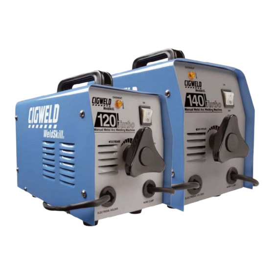
- Page 1 120 Turbo 140 Turbo Operation Manual Version No:1 Issue Date: Dec 22, 2006 Manual No: 719527 Operating Features...
- Page 2 LEADER IN ARC WELDING TECHNOLOGY We appreciate your business! Congratulations on your new CIGWELD product. We are proud to have you as our customer and will strive to provide you with the best service and reliability in the industry. This product is backed by our extensive warranty and world-wide service network.
- Page 3 Spec Number W1002000 140 Turbo Manual Metal Arc Welder Spec Number W1002100 Published by: CIGWELD Pty Ltd 71 Gower Street Preston, Victoria, Australia, 3072 www.cigweld.com.au Copyright 2007 by CIGWELD All rights reserved. A reproduction of this work, in whole or in part, without written permission of the publisher is prohibited.
-
Page 4: Table Of Contents
120 Turbo, 140 Turbo TABLE OF CONTENTS SECTION 1: Arc Welding Safety Instructions and Warnings............5 SECTION 2: Introduction ........................10 SECTION 3: Electromagnetic Compatibility ...................10 SECTION 4: General Information .....................11 SECTION 5: Safe Practices For The Use Of Welding Equipment..........12 SECTION 6: Resuscitation For Electric Shock Victims..............13 SECTION 7: Specifications.......................15... -
Page 5: Arc Welding Safety Instructions And Warnings
120 Turbo, 140 Turbo SECTION 1: Arc Welding Safety Instructions and Warnings WARNING 2 ARC WELDING can be hazardous. Protect yourself and others from possible serious injury or death. Keep children away. Pace maker wearers keep away until consulting your doctor. Do not lose these instructions. Read operating / instruction manual before installing, operating or servicing this equipment. - Page 6 120 Turbo, 140 Turbo FUMES AND GASES can be hazardous to your health. 5. Work in a confined space only if it is well ventilated, or while wearing an Welding produces fumes and gases. Breathing these air-supplied respirator. Shielding gases used for welding can displace air fumes and gases can be hazardous to your health.
- Page 7 120 Turbo, 140 Turbo 1. Keep all doors, panels, covers, and guards closed and securely in place. 6. Re-install panels or guards and close doors when servicing is finished and 2. Stop engine before installing or connecting unit. before starting engine. SPARKS can cause BATTERY GASES 1.
- Page 8 LIMITED WARRANTY: CIGWELD, A Thermadyne Company, hereafter, “CIGWELD” warrants to customers of its authorized distributors hereafter “Purchaser” that its products will be free of defects in workmanship or material. Should any failure to conform to this warranty appear within the time period applicable to the CIGWELD products as stated below, CIGWELD shall, upon notification thereof and substantiation that the product has been stored, installed, operated, and maintained in accordance with CIGWELD’s specifications, instructions, recommendations and recognized standard industry practice, and not subject to misuse, repair, neglect, alteration, or accident,...
- Page 9 Replacement parts or accessories which may affect product safety or performance and which are not manufactured, distributed or approved by CIGWELD. CIGWELD declares that, to the extent permitted by law, it hereby limits its liability in respect of the supply of goods which are not of a kind ordinarily acquired for personal, domestic or household use or consumption to any one or more of the following (the choice of which shall be at the option of CIGWELD).
-
Page 10: Introduction
If there is any damage, notify the carrier immediately to file a claim. Furnish complete information CAUTION concerning damage claims or shipping errors to: CIGWELD, Customer Care Department, 71 Gower St, Preston, Refers to possible equipment damage. Cautions will be Victoria, Australia, 3072. shown in bold type. -
Page 11: General Information
120 Turbo, 140 Turbo Safety critical equipment, e.g. guarding of industrial equipment. The health of people around, e.g. the use of pacemakers and hearing aids. Equipment used for calibration and measurement. vii) The time of day that welding or other activities are to be carried out. viii) The immunity of other equipment in the environment: the user shall ensure that other equipment being used in the environment is compatible: this may require additional protection measures. -
Page 12: Safe Practices For The Use Of Welding Equipment
Distributor. This equipment or any of its parts should not be altered from standard specification without prior written approval of CIGWELD. The user of this equipment shall have the sole responsibility for any malfunction which results from improper use or unauthorised modification from standard specification, faulty maintenance, damage or improper repair by anyone other than appropriately qualified persons approved by CIGWELD. -
Page 13: Resuscitation For Electric Shock Victims
120 Turbo, 140 Turbo 5.02 Personal Protection The radiation from an electric arc during the welding process can seriously harm eyes and skin. It is essential that the following precautions be taken: ♦ Gloves should be flameproof gauntlet type to protect hands and wrists from heat burns and harmful radiations. They should be kept dry and in good repair. - Page 14 120 Turbo, 140 Turbo 3 Place victim flat on their back on a hard surface, open 4 Begin artificial breathing - 5 full breaths in 10 seconds, airway - using head tilt and jaw support as shown. sealing nostrils with cheek or holding nose closed. 5 Check carotid pulse in neck.
-
Page 15: Specifications
120 Turbo, 140 Turbo SECTION 7: Specifications 7.01 120 Turbo and 140 Turbo Specifications Description (Refer NOTE 2) 120 Turbo 140 Turbo Product Part Number W1002000 W1002100 Cooling Fan Cooled Fan Cooled Light Duty, Medium Duty, Welder Type & Welding process Leakage reactance, Leakage reactance, Manual Metal Arc Welding... - Page 16 120 Turbo, 140 Turbo In locations in which freedom of movement is restricted, so that the operator is forced to perform the work in a cramped (kneeling, sitting or lying) position with physical contact with conductive parts; In locations which are fully or partially limited by conductive elements, and in which there is a high risk of unavoidable or accidental contact by the operator, or iii) In wet or damp hot locations where humidity or perspiration considerable reduces the skin resistance of the...
-
Page 17: Operation
120 Turbo, 140 Turbo SECTION 9: Operation Conventional operating procedures apply when using the Welding Power Source, i.e. connect work lead directly to workpiece and electrode lead is used to hold electrode. Wide safety margins provided by the coil design ensure that the Welding Power Source will withstand short term overload without adverse effects. -
Page 18: Section 11: Arc Welding Electrodes
Always store electrodes in a dry place and in their original containers. 11.05 Electrode Polarity Electrodes are generally connected to the ELECTRODE HOLDER and the WORK LEAD to the work piece but if in doubt consult your nearest accredited CIGWELD Distributor. Dec 22, 2006... -
Page 19: Section 12: Arc Welding Practice
120 Turbo, 140 Turbo 11.06 Effects of Arc Welding Various Materials a) High tensile and alloy steels The two most prominent effects of welding these steels are the formation of a hardened zone in the weld area, and, if suitable precautions are not taken, the occurrence in this zone of under-bead cracks may result. Hardened zone and under- bead cracks in the weld area may be reduced by using the correct electrodes, preheating, using higher current settings, using larger electrodes sizes, short runs for larger electrode deposits or tempering in a furnace. - Page 20 120 Turbo, 140 Turbo Figure 7 -Vertical position, butt weld Figure 8 - Vertical position, fillet weld Figure 9 - Overhead position, butt weld Figure 10 - Overhead position fillet, weld Joint Preparations 12.02 In many cases, it will be possible to weld steel sections without any special preparation. For heavier sections and for repair work on castings, etc., it will be necessary to cut or grind an angle between the pieces being joined to ensure proper penetration of the weld metal and to produce sound joints.
-
Page 21: Section 13: Arc Welding Technique
120 Turbo, 140 Turbo Open Square Butt Single Vee Butt Joint Not less than 70° Joint 1.6mm max Gap varies from 1.6mm to 4.8mm depending on plate thickness 1.6mm Not less than Single Vee Butt Joint Double Vee Butt Joint Not less than 45°... - Page 22 120 Turbo, 140 Turbo 13.03 Striking the Arc Practice this on a piece of scrap plate before going on to more exacting work. You may at first experience difficulty due to the tip of the electrode “sticking” to the work piece. This is caused by making too heavy a contact with the work and failing to withdraw the electrode quickly enough.
- Page 23 120 Turbo, 140 Turbo b) Fillet Welds These are welds of approximately triangular cross-section made by depositing metal in the corner of two faces meeting at right angles. Refer to Figure 6. A piece of angle iron is a suitable specimen with which to begin, or two lengths of strip steel may be tacked together at right angles.
-
Page 24: Section 14: Distortion
120 Turbo, 140 Turbo iii) Overhead Welds Apart from the rather awkward position necessary, overhead welding is not much more difficult that downhand welding. Set up a specimen for overhead welding by first tacking a length of angle iron at right angles to another piece of angle iron or a length of waste pipe. - Page 25 120 Turbo, 140 Turbo b) Distribution of Stresses: Distortion may be reduced by selecting a welding sequence which will distribute the stresses suitably so that they tend to cancel each other out. See Figure 26 to Figure 29 for various weld sequences. Choice of a suitable weld sequence is probably the most effective method of overcoming distortion, although an unsuitable sequence may exaggerate it.
-
Page 26: Section 15: Routine Maintenance & Inspection
If major complex subassemblies are faulty, then the Welding Power Source must be returned to an Accredited CIGWELD Service Agent for repair. - Page 27 120 Turbo, 140 Turbo 16.01 Welding Problems FAULT CAUSE REMEDY 1 Gas pockets or voids in Electrodes are damp. Dry electrodes before use. weld metal (Porosity). Welding current is too high. Reduce welding current. Surface impurities such as oil, grease, Clean joint before welding.
- Page 28 120 Turbo, 140 Turbo Welding Problems (continued) FAULT CAUSE REMEDY A groove has been Welding current is too high. Reduce welding current formed in the base metal Welding arc is too long. Reduce the length of the welding arc. adjacent to the toe of a Electrode should not be inclined less weld and has not been Angle of the electrode is incorrect.
- Page 29 Switch ON the Welding Power Source. The Welding Power Source switch is illuminated. switched OFF. C The transformer secondary has poor C Have an Accredited CIGWELD Service electrical connections. Agent repair the connection. 2 The Mains supply voltage The Welding Power Source’s duty cycle...
- Page 30 Telephone: (0 3) 9474 740 0 Facsim ile: (0 3) 9474 7391 Custom er Service & Technical Support Line: 130 0 654 674 In the interest of continuous improvement, CIGWELD Pty. Ltd. reserves the right to change International Enquiries: Telephone +61 3 9474 750 8...
Need help?
Do you have a question about the WeldSkill 120 Turbo and is the answer not in the manual?
Questions and answers