
Related Manuals for CIGWELD 170Pi


Summary of Contents for CIGWELD 170Pi
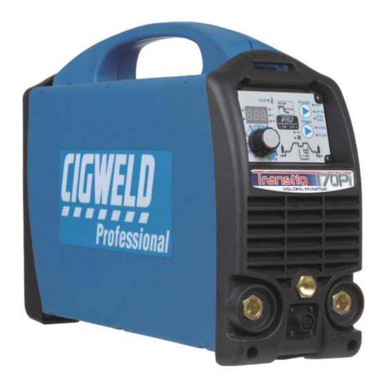
- Page 1 170Pi TRANSTIG WELDING INVERTER A-11643 Operating Manual Revision: AA Issue Date: January 10, 2013 Manual No.: 0-5241 Operating Features:...
- Page 2 To locate your nearest distributor or service provider call +1300 654 674, or visit us on the web at www.cigweld.com.au This Operating Manual has been designed to instruct you on the correct use and operation of your CIGWELD product.
- Page 3 While the information contained in this Manual represents the Manufacturer’s best judgement, the Manufacturer assumes no liability for its use. Operating Manual Number 0-5241 for: Cigweld Transtig 170Pi Inverter Plant Part Number W1007190 Cigweld Transtig 170Pi Power Source (packed) Part Number W1007189 Published by: CIGWELD Pty Ltd 71 Gower Street...
-
Page 4: Table Of Contents
3.04 Mains Supply Voltage Requirements .............. 3-1 3.05 Electromagnetic Compatibility ................ 3-1 3.06 Transtig 170Pi Power Source Controls, Indicators and Features ....3-3 3.07 Shielding Gas Regulator Operating Instructions ........... 3-14 3.08 Setup for TIG (GTAW) Welding ..............3-16 3.09 Foot Control Part No. - Page 5 KEY SPARE PARTS ................... 6-1 6.01 Power Source ....................6-1 6.02 TIG Torch W4014604 ..................6-3 APPENDIX: TRANSTIG 170Pi CIRCUIT DIAGRAM ............. A-1 CIGWELD - LIMITED WARRANTY TERMS TERMS OF WARRANTY – January 2013 WARRANTY SCHEDULE – January 2013 GLOBAL CUSTOMER SERVICE CONTACT INFORMATION...
-
Page 7: Arc Welding Safety Instructions And Warnings
TRANSTIG 170Pi SECTION 1: ARC WELDING SAFETY INSTRUCTIONS AND WARNINGS WARNING PROTECT YOURSELF AND OTHERS FROM POSSIBLE SERIOUS INJURY OR DEATH. KEEP CHILDREN AWAY. PACEMAKER WEARERS KEEP AWAY UNTIL CONSULTING YOUR DOCTOR. DO NOT LOSE THESE INSTRUCTIONS. READ OPERATING/INSTRUCTION MANUAL BEFORE INSTALLING, OPERATING OR SERVICING THIS EQUIPMENT. - Page 8 TRANSTIG 170Pi 2. Wear approved safety glasses. Side shields recom- mended. 3. Use protective screens or barriers to protect others WARNING from flash and glare; warn others not to watch the arc. ARC RAYS can burn eyes and skin; NOISE can damage hearing.
- Page 9 TRANSTIG 170Pi 3. Remove all flammables within 35 ft (10.7 m) of the welding arc. If this is not possible, tightly cover them with approved covers. WARNING 4. Be alert that welding sparks and hot materials from FUMES AND GASES can be hazardous to welding can easily go through small cracks and your health.
- Page 10 TRANSTIG 170Pi 5. Use only correct shielding gas cylinders, a very large volume of scientific findings based on regulators, hoses, and fittings designed for the experiments at the cellular level and from studies specific application; maintain them and associated with animals and people which clearly establish that parts in good condition.
-
Page 11: Principal Safety Standards
TRANSTIG 170Pi 1.02 Principal Safety Standards Safety in Welding and Cutting, ANSI Standard Z49.1, from American Welding Society, 550 N.W. LeJeune Rd., Miami, FL 33126. Safety and Health Standards, OSHA 29 CFR 1910, from Superintendent of Documents, U.S. Government Printing Office, Washington, D.C. 20402. -
Page 12: Declaration Of Conformity
71 Gower St, Preston Victoria 3072 Australia Description of equipment: Welding Equipment (GTAW, MMAW) including, but not limited to CIGWELD Transtig 170Pi Welding Inverter and associated accessories. Serial numbers are unique with each individual piece of equipment and details description, parts used to manufacture a unit and date of manufacture. -
Page 13: Introduction
Use care to avoid damaging the Additional copies of this manual may be purchased by equipment when using bars, hammers, etc., to un- contacting Cigweld at the address and phone number crate the unit. for your location listed in the inside back cover of this manual. -
Page 14: Symbol Chart
TRANSTIG 170Pi 2.04 Symbol Chart Note that only some of these symbols will appear on your model. Wire Feed Function Single Phase Wire Feed Towards Workpiece With Three Phase Output Voltage Off. Three Phase Static Frequency Converter- Dangerous Voltage Welding Gun... -
Page 15: Description
TRANSTIG 170Pi 2.05 Description 2.07 Transporting Methods The Cigweld Transtig 170Pi is a self contained single This unit is equipped with a handle for carrying phase multi process welding inverter that is capable purposes. of performing MMAW (Stick) and GTAW (HF and Lift TIG) welding processes. -
Page 16: Duty Cycle
(170A) for 3.0 minutes, i.e. arc welding time, out of every 10 minute period (30% of 10 minutes is 3.0 minutes). During the other 7.0 minutes of the 10 minute period the Welding Power Source must idle and be allowed to cool. A-11644 Figure 2-1: Transtig 170Pi Duty Cycle INTRODUCTION Manual 0-5241... -
Page 17: Specifications
130A @ 60%, 15.2V 100A @ 100%, 14.0V Protection Class IP23S Table 2-1: Transtig 170Pi Specifications NOTE 1 Due to variations that can occur in manufactured products, claimed performance, voltages, ratings, all capacities, measurements, dimensions and weights quoted are approximate only. Achievable capacities and ratings in use and operation will depend upon correct installation, use, applications, maintenance and service. -
Page 18: Options And Accessories
Minimum Generator Recommendation at the Maximum Output Duty Cycle. Due to large variations in performance and specifications of different brands and types of genera- tors, Cigweld cannot guarantee full welding output power or duty cycle on every brand or type of generator. -
Page 19: Installation, Operation And Setup
TRANSTIG 170Pi SECTION 3: INSTALLATION, OPERATION AND SETUP conditions. For further information please refer 3.01 Environment to AS 60529. These units are designed for use in environments with H. Precautions must be taken against the power increased hazard of electric shock as outlined in AS source toppling over. - Page 20 TRANSTIG 170Pi action may be as simple as earthing the welding C. Methods of Reducing Electromagnetic circuit, see NOTE below. In other cases it could Emissions involve constructing an electromagnetic screen 1. Mains Supply enclosing the Welding Power Source and the work, complete with associated input filters.
-
Page 21: Transtig 170Pi Power Source Controls, Indicators And Features
Selective screening and shielding of other cables and equipment in the surrounding area may alleviate problems of interference. Screening the entire welding installation may be considered for special applications. 3.06 Transtig 170Pi Power Source Controls, Indicators and Features A-11646 A-11645... - Page 22 If you are in "amps display" mode, when not welding, long press of more than 2 seconds on the Multi Function Control will set the 170Pi to "volts display" mode, the meter will show actual output volts for 5 seconds, then revert to "amps display" and allows adjustment of parameters. During welding, the meter will show actual welding volts when selected.
- Page 23 TRANSTIG 170Pi A-11647 Figure 3-3: Programming Mode STICK Programming Mode Programming Parameter Control Panel Display Hot Start Th is pa ra me ter ope rate s i n STICK mode to improve the start characteristics for stick electrodes HOT START current is on top of the BASE current.
- Page 24 TRANSTIG 170Pi Programming Parameter Control Panel Display Arc Force Arc Force is effective when in STICK mode only. Arc Force control provides an adjustable amount of Arc Force (or "dig") control. This feature can be particularly beneficial in providing the operator the ability...
- Page 25 TRANSTIG 170Pi Up Slope This parameter operates in TIG modes only and is used to set the time for the weld current to ramp up from INITIAL current to BASE current. Range is 0.0 to 15.0 seconds. Factory default is 1.0 second.
- Page 26 TRANSTIG 170Pi Pulse Mode / Direct DC mode This parameter selects PULSE operating mode or DIRECT DC (-) operating mode. Range is DC or Pulse Mode. Factory default is DC. Trough Current This parameter sets the TIG TROUGH current. The lowest point in the pulse is called the Trough.
- Page 27 TRANSTIG 170Pi Pulse Width This parameter sets the percentage “on” time of the PULSE FREQUENCY for BASE weld current when in PULSE operating mode. Range is 15 to 80%. Factory default is 50%. Pulse Frequency This parameter sets the PULSE FREQUENCY when in PULSE operating mode.
- Page 28 TRANSTIG 170Pi Crater Current This parameter operates in TIG modes only. In 2T mode this is the current at the end of the down slope current ramp. When the welding current reaches the Crater Current value, the welding current will cease and the unit will enter Post Flow mode.
- Page 29 TRANSTIG 170Pi CAUTION Loose welding terminal connections can cause overheating and result in the male plug being fused in the bayonet terminal. 7. Remote Control Socket The 8 pin Remote Control Socket is used to connect remote control devices to the welding power source.
- Page 30 TRANSTIG 170Pi A-11663 4T Latch Mode This mode of welding is mainly used for long welding runs to reduce operator fatigue. In this mode the operator can press and release the torch trigger and the output will remain active. To deactivate the power source, the trigger switch must again be depressed and released, thus eliminating the need for the operator to hold the torch trigger.
- Page 31 14. Fan on Demand The Transtig 170Pi is fitted with a fan on demand feature. Fan on demand automatically switches the cooling fan off when it is not required. This has two main advantages; (1) to minimize power consumption, and (2) to minimize the amount of contaminants such as dust that are drawn into the power source.
-
Page 32: Shielding Gas Regulator Operating Instructions
TRANSTIG 170Pi 3.07 Shielding Gas Regulator Operating Instructions WARNING This equipment is designed for use with welding grade (Inert) shielding gases only. Shielding Gas Regulator Safety This regulator is designed to reduce and control high pressure gas from a cylinder or pipeline to the working pressure required for the equipment using it. - Page 33 TRANSTIG 170Pi Installation 1. Remove cylinder valve plastic dust seal. Clean the cylinder valve outlet of impurities that may clog orifices and damage seats before connecting the regulator. Crack the valve (open then close) momentarily, pointing the outlet away from people and sources of ignition.
-
Page 34: Setup For Tig (Gtaw) Welding
TRANSTIG 170Pi Shutdown Close cylinder valve whenever the regulator is not in use. To shut down for extended periods (more than 30 minutes). 1. Close cylinder or upstream valve tightly. 2. Open downstream equipment valves to drain the lines. Bleed gas into a well ventilated area and away from any ignition source. -
Page 35: Foot Control Part No. W4015800 (Optional Accessory)
TRANSTIG 170Pi A-11666 Figure 3-7: Setup for TIG Welding 3.09 Foot Control Part No. W4015800 (Optional Accessory) Art # A-11338 Figure 3-8: Foot Control Art # A-11339 Art # A-11340 Figure 3-9: 8 Pin Control Plug Description Not Used Trigger Switch... - Page 36 TRANSTIG 170Pi Description The CIGWELD Foot Control is a foot operated switch and potentiometer which starts and stops the welding process and controls welding current through operation of the foot pedal. Refer to list below for compatible Cigweld power sources.
-
Page 37: Setup For Manual Arc (Mmaw) Welding
TRANSTIG 170Pi 3.10 Setup for Manual Arc (MMAW) Welding A. Connect the Electrode Holder lead to the positive welding terminal (+). If in doubt, consult the electrode manufacturer. Welding current flows from the Power Source via heavy duty bayonet type terminals. It is essential, however, that the male plug is inserted and turned securely to achieve a sound electrical connection. - Page 38 TRANSTIG 170Pi INSTALLATION, OPERATION AND SETUP 3-20 Manual 0-5241...
-
Page 39: Basic Welding Guide
Electrodes are generally connected to the ELECTRODE HOLDER with the Electrode Holder connected positive polarity. The WORK LEAD is connected negative polarity and is connected to the work piece. If in doubt consult the electrode data sheet or your nearest Accredited CIGWELD Distributor. Effects of Arc Welding Various Materials A. - Page 40 TRANSTIG 170Pi Welding Position The electrodes dealt with in this publication can be used in most positions, i.e. they are suitable for welding in flat, horizontal, vertical and overhead positions. Numerous applications call for welds to be made in positions intermediate between these.
- Page 41 TRANSTIG 170Pi Art# A-07693 Figure 4-7: Overhead Position, Butt Weld Art # A-07694 Figure 4-8: Overhead Position, Fillet Weld Joint Preparations In many cases, it will be possible to weld steel sections without any special preparation. For heavier sections and for repair work on castings, etc., it will be necessary to cut or grind an angle between the pieces being joined to ensure proper penetration of the weld metal and to produce sound joints.
- Page 42 TRANSTIG 170Pi Arc Welding Technique - A Word to Beginners For those who have not yet done any welding, the simplest way to commence is to run beads on a piece of scrap plate. Use mild steel plate about 6.0mm thick and a 3.2mm electrode. Clean any paint, loose scale or grease off the plate and set it firmly on the work bench so that welding can be carried out in the downhand position.
- Page 43 TRANSTIG 170Pi If the travel is too fast, the bead will be narrow and strung out and may even be broken up into individual globules. If the travel is too slow, the weld metal piles up and the bead will be too large.
- Page 44 TRANSTIG 170Pi from the vertical. Some electrodes require to be sloped about 20º away from the perpendicular position to prevent slag from running ahead of the weld. Refer to Figure 4-13. Do not attempt to build up much larger than 6.4mm width with a 3.2mm electrode, otherwise the weld metal tends to sag towards the base, and undercut forms on the vertical leg.
- Page 45 TRANSTIG 170Pi Art # A-07702 Figure 4-16: Multi Run Vertical Fillet Weld Art # A-07703 Figure 4-17: Examples of Vertical Fillet Welds 2. Vertical Down The Ferrocraft 21 electrode makes welding in this position particularly easy. Use a 3.2mm electrode at 100 amps.
- Page 46 TRANSTIG 170Pi Distortion Distortion in some degree is present in all forms of welding. In many cases it is so small that it is barely perceptible, but in other cases allowance has to be made before welding commences for the distortion that will subsequently occur.
- Page 47 TRANSTIG 170Pi B. Distribution of Stresses Distortion may be reduced by selecting a welding sequence which will distribute the stresses suitably so that they tend to cancel each other out. See Figures 4-20 through 4-23 for various weld sequences. Choice of a suitable weld sequence is probably the most effective method of overcoming distortion, although an unsuitable sequence may exaggerate it.
- Page 48 TRANSTIG 170Pi Art # A-07710_AB Block Sequence. The spaces between the welds are filled in when the welds are cool. Figure 4-24: Welding Sequence Art # A-07711_AB Figure 4-25: Step back Sequence Art # A-07712 Figure 4-26: Chain Intermittent Welding...
- Page 49 It Blisterpack Blisterpack 322217 has better “wetting” action than Castcraft 55. 4.0mm 2.5 kg 611734 Table 4-1: Cigweld Electrode Selection Chart Further information on CIGWELD electrodes can be found at the website www.cigweld.com.au. Manual 0-5241 4-11 BASIC WELDING GUIDE...
-
Page 50: Stick (Mmaw) Welding Troubleshooting
TRANSTIG 170Pi 4.02 Stick (MMAW) Welding Troubleshooting FAULT CAUSE REMEDY 1 Welding current ARC FORCE is set at a val- Reduce the ARC FORCE until welding current is varying ue that causes the welding reasonably constant while prohibiting the elec-... - Page 51 TRANSTIG 170Pi 5 Portions of the A Small electrodes used on A Use larger electrodes and preheat the plate. weld run do not heavy cold plate. fuse to the surface B Welding current is too low. B Increase welding current.
-
Page 52: Tig (Gtaw) Basic Welding Technique
TRANSTIG 170Pi 4.03 TIG (GTAW) Basic Welding Technique Gas Tungsten Arc Welding (GTAW) or TIG (Tungsten Inert Gas) as it is commonly referred to, is a welding process in which fusion is produced by an electric arc that is established between a single tungsten (non- consumable) electrode and the work piece. - Page 53 TRANSTIG 170Pi Tungsten Electrode Types Electrode Type Welding Application Features Colour Code (Ground Finish) DC welding of mild Excellent arc starting, Thoriated 2% steel, stainless steel Long life, High current and copper carrying capacity High quality AC weld- Self cleaning, Long...
-
Page 54: Tig (Gtaw) Welding Problems
Arc Welding section are applicable a comprehensive outline of the TIG Welding process is outside the scope of this Operating Manual. For further information please refer to www. cigweld.com.au or contact Cigweld. 4.04 TIG (GTAW) Welding Problems... - Page 55 Electrode Selection Chart. B The wrong electrode B Select the right size tungsten electrode is being used for the type. Refer to Table 4-5 Cigweld Tungsten welding job. Electrode Selection Chart. C Gas flow rate is too C Select the right shielding gas flow rate for high.
- Page 56 TRANSTIG 170Pi BASIC WELDING GUIDE 4-18 Manual 0-5241...
-
Page 57: Power Source Problems And Routine Service Requirements
D Empty gas cylinder. D Replace gas cylinder. 5 Gas flow continues after A Gas valve has jammed open A Have an accredited CIGWELD the torch trigger switch has due to impurities in the gas service provider repair or replace been released (TIG mode). -
Page 58: Routine Service And Calibration Requirements
The inspection and testing of the power source and associated accessories shall be carried out in accordance with Section 5 of AS 1674.2 - 2007: Safety in Welding and Allied Processes-Part 2 Electrical. This includes an insulation resistance test and an earthing test to ensure the integrity of the unit is compliant with Cigweld's original specifications. - Page 59 2. The earth terminal of the associated plug of a transportable power source Note that due to the dangers of stray output currents damaging fixed wiring, the integrity of fixed wiring supplying Cigweld welding power sources should be inspected by a licensed electrical worker in accordance with the requirements below - 1.
- Page 60 Output current (A) to be checked to ensure it falls within applicable Cigweld power source specifications Output Voltage (V) to be checked to ensure it falls within applicable Cigweld power source specifications Accuracy of digital meters to be checked to ensure it falls within applicable Cigweld power source specifi- cations...
-
Page 61: Cleaning The Welding Power Source
TRANSTIG 170Pi 5.03 Cleaning the Welding Power Source WARNING There are dangerous voltage and power levels present inside this product. Do not attempt to open or repair unless you are a qualified electrical tradesperson. Disconnect the Welding Power Source from the Mains Supply Voltage before disassembling. - Page 62 TRANSTIG 170Pi POWER SOURCE PROBLEMS AND ROUTINE SERVICE REQUIREMENTS 5-6 Manual 0-5241...
-
Page 63: Key Spare Parts
TRANSTIG 170Pi SECTION 6: KEY SPARE PARTS 6.01 Power Source A-11668 Figure 6-1 Manual 0-5241 KEY SPARE PARTS... - Page 64 TRANSTIG 170Pi TRANSTIG 170Pi POWER SOURCE SPARE PARTS ITEM PART NUMBER DESCRIPTION W7005815 PCB Power W7005801 PCB Control W7005802 PCB HF Generator W7005803 PCB Front Panel (Display) W7005805 Knob Control W7004909 Dinse Socket 50mm Control Socket 8 pin (Note that 8 pin control plug is part number...
-
Page 65: Tig Torch W4014604
TRANSTIG 170Pi 6.02 TIG Torch W4014604 TIG Torch W4014604 spare parts diagram A-11669 Figure 6-2 TIG TORCH SPARE PARTS ITEM PART NO. DESCRIPTION W7005900 Trigger assembly for 26F torch W7005901 Handle assembly for 26F torch W7005902 Dinse 50mm for 26F torch... -
Page 66: Appendix: Transtig 170Pi Circuit Diagram
TRANSTIG 170Pi APPENDIX: TRANSTIG 170Pi CIRCUIT DIAGRAM SOU HF A-11670 Manual 0-5241 APPENDIX... -
Page 67: Cigweld - Limited Warranty Terms
WELD whether arising out of contract, negligence, strict tort, or under any warranty, or otherwise, shall not, except as expressly provided herein, exceed the price of the goods upon which such liability is based. No employee, agent, or representative of CIGWELD is authorized to change this warranty in any way or grant any other warranty. - Page 68 CIGWELD. 4. CIGWELD declares that, to the extent permitted by law, it hereby limits its liability in respect of the supply of goods which are not of a kind ordinarily acquired for personal, domestic or household use or consumption to any one or more of the following (the choice of which shall be at the option of CIGWELD).
- Page 69 Accredited Distributor of the equipment. Notwithstanding the foregoing, in no event shall the warranty period extend more than the time stated plus one year from the date CIGWELD delivered the product to the Accredited Distributor. Unless otherwise stated the warranty period includes parts and labour. CIGWELD reserves the right to request documented evidence of date of purchase.
- Page 70 To make a claim under the warranty, take the product (with proof of purchase from a Cigweld Accredited Seller) to the store where you purchased the product or contact Cigweld Customer Care 1300 654 674 for advice on your nearest Service Provider.
- Page 71 GLOBAL CUSTOMER SERVICE CONTACT INFORMATION CIGWELD, Australia Victor Technologies, China No 100 Lao Hongjing Rd 71 Gower Street Preston, Victoria Minhang District Australia, 3072 Shanghai, PR, 200235 Telephone: 86-21-64072626 Telephone: 61-3-9474-7400 Fax: 61-3-9474-7391 Fax: 86-21-64483032 Email: enquiries@cigweld.com.au Victor Technologies Asia Sdn Bhd...
- Page 72 Asia Pacific Regional Headquarters 71 Gower Street Preston, Victoria, Australia, 3072 Telephone: +61 3 9474 7400 FAX: +61 3 9474 7391 Email: enquiries@cigweld.com.au www.cigweld.com.au...
Need help?
Do you have a question about the 170Pi and is the answer not in the manual?
Questions and answers