Table of Contents
Advertisement
1
2
3
4
EASY
EXTENDED
81801G_MHW_1200-1300_07-2011_ENG
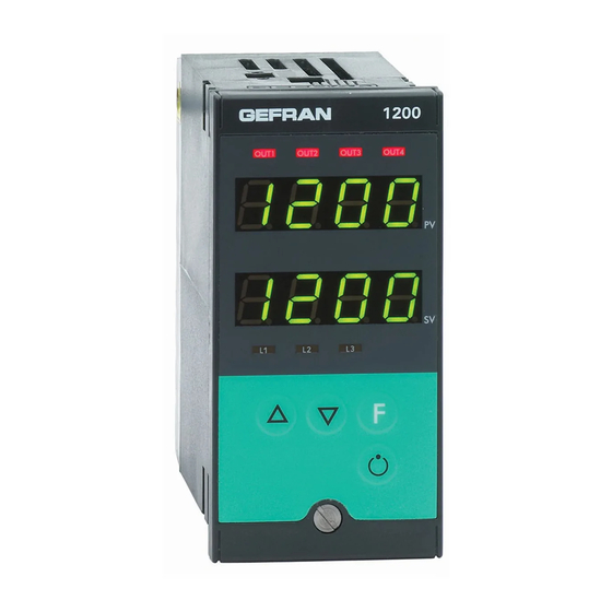
1200 / 1300
TEMPERATURE CONTROLLER
GENERAL INDEX
page
2
2
2
2
2
2
3
3
4
4
4
4
5
6
6
6
6
6
7
9
10
10
11
12
13
14
19
INSTRUCTIONS FOR USE
AND WARNINGS
Software Version 4.0x
code 81801G / Edition 08 - 07/2011 ENGLISH
Twin setpoint application (Ramp +
Hold + Time expiration alarm)
Heating/Cooling control with
Relative gain
5
6
7
Accessories
RS232/TTL interface for Gefran
Instrument configuration
The contents of each section are summarized
immediately following the section heading
page
30
30
30
30
30
31
31
31
32
32
33
33
33
34
35
35
35
35
35
36
36
37
37
37
38
1
Advertisement
Table of Contents

Related Manuals for gefran 1200


Summary of Contents for gefran 1200
-
Page 1: Table Of Contents
1200 / 1300 TEMPERATURE CONTROLLER INSTRUCTIONS FOR USE AND WARNINGS Software Version 4.0x code 81801G / Edition 08 - 07/2011 ENGLISH GENERAL INDEX page page Application notes Graphic symbol used Preliminary instructions HB Alarm General description HOLD function Basic version controller... -
Page 2: Graphic Symbol Used
They represent an exclusive combination • 1 universal input for TC, 2/3 wire RTD, PTC, NTC, performance, reliability and applicational flexibility. In particular, this new line of Gefran tempera- and linear thermocouples, supplied with current and ture controllers is the ideal solution for application voltage with accuracy better than 0.2% f.s. -
Page 3: Operator Interface
Lexan that guarantees IP65 level protection. • Mains voltage supply • 4 buttons to be used for manual regulation/ Example: 1200 – RT – RR – 00 – 0 – 1 configuration/selection Model 1200 controller • 2 green four-digit displays Output 1 - Relay; Output 2 - Triac (1A) (Process Variable and Set point Variable) Output 3 - Relay;... -
Page 4: Installation And Connection
2 • INSTALLATION AND CONNECTION This section contains the instructions necessary damage to persons, machinery or materials, it is for correct installation of the 1200/1300 essential to connect it up to auxiliary alarm controllers into the machine control panel or the equipment. -
Page 5: Instrument Power Supply
• Fit a 1N4007 diode in parallel with the coil of the - the Ohmic resistance must be <6W; inductive loads that operate in Direct Current. • If the mains voltage fluctuates strongly, use a volta- GEFRAN S.p.A. declines all responsibility for ge stabilizer. any damage to persons or property caused • In the proximity of high frequency generators or arc by tampering, neglect, improper use or any welders, use adequate mains filters. -
Page 6: Dimensions And Cut-Out
Example: 1200/1300 – xx – xx – xx – x – 1 = 100..240Vac/dc 1200/1300 – xx – xx – xx – x – 0 = 11..27Vac/dc 81801G_MHW_1200-1300_07-2011_ENG... -
Page 7: Electrical Connections
Electrical Connections 1200 Outputs Out3 - Out4 Outputs Out1 - Out2 Digital inputs CT Input Serial line Inputs Always make the connections using cable types suitable for the voltage and current limits given in Section 5 - Technical Specifications. If the Controller has faston terminals these must be protected and isolated. - Page 8 Inputs Linear input (V) PTC/NTC/Pt100/JPT100 input Jumper S2 closed on CPU board Linear input in (see CAP. 6 Direct Current Maintenance) 60 mV, 1V (Ri > 1MW) 5V, 10V (Ri > 10KW) Use wires of adeguate diameter (min. 1mm 2-wire connection 3-wire connection Outputs Out1, Out 2 User configurable generic outputs...
-
Page 9: Example Of Connection With Tc Input Electric Heating With Power Solid State Relay And Water Cooling With Solenoid Valve
Serial line Modbus 2 wires (Standard) Modbus 4 wires / Cencal RS485 isolated serial line RS485 isolated serial line For configuration Modbus 4 wires/Cencal. (data -) (data +) Example of connection with TC Input Electric heating with power solid state relay and water cooling with solenoid valve OUT1 relay OUT2 logic 81801G_MHW_1200-1300_07-2011_ENG... -
Page 10: Functions
This section illustrates the functions and operating modes of the displays, the indicator lights and the buttons that make up the operator interface of series 1200/1300 controllers. It is therefore an essential requirement for programming and configuring the controllers correctly. -
Page 11: General Operating Notes
General Operating Notes Switching on and using the Controller Self-diagnostics • Immediately after switching on the controller carries out a self-diagnostic test. During the test, all the display segments and the 7 indicator lights will flash. • If the self-diagnostics procedure does not detect any errors the controller enters the normal working status (Level 1) • Any errors found by the self-diagnostics are memorized in a record and can be displayed with the ERR function in the INF menu Normal Working - Level 1 PV Displays the value of the Process Variable. -
Page 12: Navigating Through The Controller Menu
Navigating through the Controller Menu Keep pressed down to scroll through the menus in sequence and release it when the required menu appears. Press to access the parameters of the selected menu. Keep to return immediately to level 1. Level 1 Display Menu 39. -
Page 13: Configuration And Programming
Integral heating time [0.0 ... 99.99] % f.s. 4. 0 0 Optimal working operation of the 1200/1300 Controller in the field of application it is intended for depends largely on correct (default value) configuration and programming of the relevant control parameters. - Page 14 EASY Configuration/Programming Standard for instrument with 2 Outputs: OUT1 = AL1 / OUT2 = MAIN HEAT In the EASY configuration, the general navigation flow shown at the end of Section 3 - Functions is considerably simplified, as illustrated in the following figure. Level 1 display Menu 39.
- Page 15 -Easy- Configuration Fourth menu to set up This menu is used to configurare the control parameters in the Easy mode. S.tun Continuous Selftuning Softstart autotunig Enabling self-tuning, autotuning, S. v softstart (**) S.tun Single action Selftuning Softstart Autotuning WAIT WAIT WAIT *) By adding the following figures to the value indicated in the table it is possible to enable a series of supplementary functions:...
- Page 16 -Easy- Inputs Settings Third menu to set up Probe type Without dec. With dec. point point DP. S = 0 DP. S = 1 Sensore: TC J °C 0/1000 0.0/999.9 TC J °F 32/1832 32.0/999.9 TC K °C 0/1300 0.0/999.9 Type of probe, signal, custom line- arization enabling and main scale input...
- Page 17 -Easy- Outputs Settings Second menu to set up This menu is used to configure the type of Alarm 1 and the Output 2 cycle time. Direct A1. T (high limit Normal Inverse Absolute/Relative Symmetric (low limit) to active Setpoint (window) AI.
- Page 18 -Easy- Protection code This menu is used to enable or disable the display and/or editing of certain parameters and to access the exten- ded configuration. Display Modification SP, alarms SP, alarms SP, alarms By adding the following amounts to the values shown in the table a series of supplementary functions can be enabled: to disable INP, 0VT...
-
Page 19: Configuration/Programming
Information display Extended programming configuration This menu provides information on the status and hardware configuration of the controller (number and type of inputs/outputs, software version, etc.). Software version 2. 0 i Instrument code Self diagnostic error code no error Where there is an error in recognising the boards the value displayed is increased by +8: Configuration G. - Page 20 Configuration Fourth menu to set up This menu makes it possible to configure various control parameters. S.tun Continuous Selftuning Softstart autotunig Enabling self-tuning, autotuning, S. v softstart (**) Proportional band for heating or hysteresis h. P b for ON/OFF control 1.
- Page 21 [ gfg ] c. L Minimum power limit for cooling (not available for heating/cooling double action 0. 0 [0.0 ... 100.0] % Manual Reset S r t [-999 ... +999] scale points Reset power P. S 0. 0 [-100.0 ... +100.0] % Antireset A.
- Page 22 This menu makes it possible to configure the various parameters that control serial communication between the controller and the supervisor. Instrument identification code [0 ... 247] Serial interface protocol Serial protocol SR. P [0 ... 1] CENCAL Gefran MODBUS RTU Select Baudrate Baudrate 1200 [0 ... 4] 2400 4800...
- Page 23 InP Input settings third menu to set up This menu makes it possible to configure the parameters for the Controller input signals. Type of remote setpoint, Absolute / Relative SP. R Digital (from serial line) Absolute Def. remote setpoint Digital (from serial line) Relative to SP or SP1 or SP2 sets [0 ...
- Page 24 DP.S Format Decimal point position for input xxxx dP. S scale xxx.x xx.xx (*) x.xxx (*) not available for TC, RTD, PTC, NTC probes Lo. S Minimum limit of main input scale Min... Max value associated with the input selected with the TYP parameter Ki .
- Page 25 0VT Output settings Second menu to set up This menu makes it possible to configure the parameters of the Controller outputs. A 1. R Select reference signal for alarm i. A A2. R Variable to compare Alarm setpoint A3. R PV (process variable) SV (active setpoint) AL only absolute...
- Page 26 RL. 1 ; RL. 2 RL. 3 ; RL. 4 Function HEAT (control output for heating) COOL (control output for cooling) OUT 1 AL1 – alarm 1 Allocation of reference signal AL2 – alarm 2 AL3 – alarm 3 AL. HB – HB alarm LBA –...
- Page 27 Protection code P R O This menu makes it possible to enable/disenable the display and/or modification of specific parameters and to access the Easy configuration. (For the access to this menu please refer to the section “Navigation in the menus of the controller”) Display Modification SP, IN2, alarms, 0VP, INF...
- Page 28 Alarm 1 Alarm 2 Alarm 3 AL. N disabled disabled disabled enabled disabled disabled Select number of enabled alarms disabled enabled disabled enabled enabled disabled disabled disabled enabled enabled disabled enabled disabled enabled enabled enabled enabled enabled By adding the following figures to the value in the table it is possible to enable a series of supplementary functions: to enable HB alarm +16:...
-
Page 29: User Calibration
Input linearization L ’ N This menu makes it possible to carry out custom linearization for the main input. i L n Step 0 (beginning of scale value) Display limits: [-1999 ... 9999] ..The “n” step value corresponds to input: mV beginning scale + n* mV mV = (mV full scale - mV beginning scale) / 32 Step 32 (full scale value) -
Page 30: Hb Alarm
Application Notes HB Alarm This type of alarm depends on use of the current transformer (C.T.) input. It can signal variations in load input by identifying the current value in ammeter input in the range (0 ... HS.2). It is enabled by means of configuration code (AL.n);... -
Page 31: Manual Tuning
If the Integral Time value is too long (Weak integral action), deviation between the controlled variable and the set- point may persist. Contact GEFRAN for more information on control actions. Manual Tuning A) Enter the setpoint at its working value. -
Page 32: Software On/Off Switching Function
Software ON/OFF switching function How to switch the unit OFF: hold down the “F” and “Raise” keys simultaneously for 5 seconds to deactivate the unit, which will go to the OFF state while keeping the line supply connected and keeping the process value displayed. The SV display is OFF. -
Page 33: Auto-Tuning
Auto-Tuning Enabling the auto-tuning function blocks the PID parameter settings. It can be one of two types: permanent (continuous) or single-action (one-shot). * Continuous auto-tuning is activated via the Stu parameter (values 1, 3, 5). It continuously reads system oscillations, immediately seeking the PID parameter values that reduce the current oscillation. It does not engage if the oscillations drop below 1.0% of the proportional band. -
Page 34: Technical Specifications
5 • TECHNICAL SPECIFICATIONS This section contains a list of the Technical Specifications for the 1200/1300 Controller. Display 2x4 digits, green, height 10 and 7mm Keys 4 mechanical keys (Man/Auto, INC, DEC, F) Accuracy 0.2% f.s. ±1 at 25°C room temperature Thermal drift 0.005% f.s. -
Page 35: Maintenance
When it is switched on again a self- illegible diagnostic test is performed that checks intermittent start up of all the segments (displays the value 8888). If one or more segments do not light up contact your Gefran dealer. When pressing down none... -
Page 36: Technical-Commercial Information
Gefran Customer Care Service is contacted for assistance with any problems. Order code - Temperature Controller 1200/1300... -
Page 37: Ptc
• ORDER CODE Wire material: Unipolar in PVC (12/0,18) Wire length: 5,50m PTC 7 x 25 5m • Interface for GEFRAN instrument configuration Kit for PC via the USB port (Windows environment) for GEFRAN instruments configuration: KIT PC USB / RS485 o TTL Lets you read or write all of the parameters • A single software for all models • Easy and rapid configuration • Saving and management of parameter recipes... -
Page 38: Appendix
APPENDIX The appendix contains the list of all the abbreviations of parameters which appear in the various configu- ration/programming menus with the respective default values and meanings. The CONF column can be used to indicate the user’s modified values with respect to the default configu- ration, on the basis of application requirements. - Page 39 Display Default CONF Acronym Description Menu SER Instrument Code Instrument identification code Serial Protocol Serial interface protocol SR. P bAudrate Baudrate selection PArity Parity selection S. Input Virtual instrument inputs S. I N S. Output Virtual instrument outputs S. 0 V S.
- Page 40 L’ N Menu - S00 – S35 Inputs linearization N° Default CONF N° Default CONF N° Default CONF N° Default CONF N° Default CONF S.00 S.08 S.16 S.24 S.32 1000 S.01 S.09 S.17 S.25 0.00 S.02 S.10 S.18 S.26 S.34 0.00 S.03 S.11...
Need help?
Do you have a question about the 1200 and is the answer not in the manual?
Questions and answers