Table of Contents
Advertisement
Quick Links
Advertisement
Table of Contents

Related Manuals for Quest Engineering Q1K


Summary of Contents for Quest Engineering Q1K
- Page 1 Owner’s Manual...
-
Page 2: Product Overview
Product Overview Ultra small in size and big on features, this small footprint high fidelity amplifier is an audio powerhouse. Either as a standalone studio quality stereo amplifier, or as a part of a more complex multi channel system, the Q is the system designer’s ideal solution. -
Page 3: General Caution
General Caution • Do not expose the unit to any moisture • When cleaning the unit, ensure it has been whether rain, water or other liquids. Exposure disconnected from any power source and to moisture could result in damage to internal that only a dry cloth is used. -
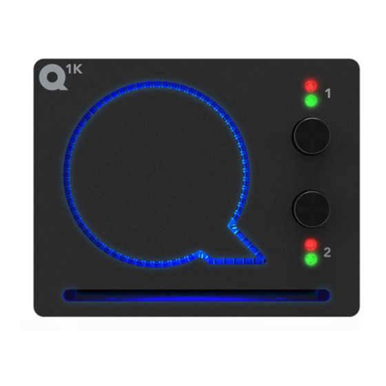
Page 4: Front Panel Controls
Front Panel Controls Channel 1 Clip Indicator Channel 1 Signal Indicator Channel 1 Level Control Channel 2 Level Control Channel 2 Clip Indicator Channel 2 Signal Indicator Figure 1.00 Amplifier Connections Balanced Input Connectors Plug: 2x 5.08mm 3-Way Captive Screw Plug Speaker Output Connector Plug: 5.08mm 4-Way Locking Captive Screw Plug Figure 1.01... - Page 5 Ampli er Wiring Unbalanced Wiring Balanced Wiring + Hot - Cold Ground Unbalanced Wiring Balanced Wiring + Positive - Negative Speaker Wiring + Positive - Negative Bridged Speaker Wiring Figure 1.02...
-
Page 6: Amplifier Operation
Amplifier Operation Behind the Q ’s ‘Q’ device is an impressive selection of switchable functions. Simply remove the badge (with the provided Quest TL02 tool), and an installer can configure a range of filter settings and amplifier modes. The ‘Q’ device also provides some security when it comes to setting selection, as it appears to be a fixed item, and also requires the TL_02 to remove adds piece of mind to your installation. -
Page 7: Dip Switch Settings
DIP Switch Settings DIP Switch Settings: CH1 85Hz High Pass Filter CH1 100Hz Low Pass Filter CH2 85Hz High Pass Filter CH2 100Hz Low Pass Filter Low Impedance Bridge Mode (summed inputs - ganged gain controls) DIP Switch Settings: High Impedance Bridge Mode (summed inputs - ganged gain controls) DIP Switch Settings: Summing Mode... -
Page 8: Amplifier Configurations
Amplifier Configurations INPUT AMPLIFIER FILTERS SUMMING CIRCUIT INPUT AMPLIFIER FILTERS Figure 1.05 (Normal Dual Channel Mode) INPUT AMPLIFIER FILTERS SUMMING CIRCUIT INPUT AMPLIFIER FILTERS CONTROLS LINKED Figure 1.06 (Bridged Mode (both low and high impedance variants)) INPUT AMPLIFIER FILTERS SUMMING CIRCUIT INPUT AMPLIFIER... -
Page 9: Cooling And Ventilation
Cooling and Ventilation Air is drawn in from the front panel and passed out the rear panel. It is essential that while the amplifier is running air is able to circulate around it freely. The efficiency of the cooling system will depend on the immediate environment (e.g. -
Page 10: Specifications
* Quest Engineering reserves the right to make changes in specifications, or products without prior notice. ** The figures shown above are ‘real world’, usable specifications and are conservative as a result. Quest Engineering does not believe in portraying misleading or exaggerated specifications. - Page 12 Register Your Product Thank you for choosing Quest. Please take the time to complete your product registration. Registering your Quest Engineering product will: • CONFIRM YOUR WARRANTY • REGISTER YOUR PRODUCT • PROTECT YOUR NEW PRODUCT REGISTER ONLINE: www.questengineering.com.au/registration For spare parts and service, contact your local authorised Quest Dealer.
Need help?
Do you have a question about the Q1K and is the answer not in the manual?
Questions and answers