Table of Contents
Advertisement
Quick Links
Advertisement
Table of Contents

Related Manuals for Quest Engineering M120


Summary of Contents for Quest Engineering M120
- Page 1 Owner’s Manual M120...
- Page 2 WARNING TO PREVENT THE RISK OF SHOCK OR FIRE. DO NOT USE THIS CORD WITH AN EXTENSION, RECEPTACLE OR ANY OTHER OUTLET UNLESS THE BLADES CAN BE FULLY CUT. PLEASE MATCH THE WIDE BLADE WITH THE WIDE SOCKET OPENING. TO PREVENT THE RISK OF SHOCK OR FIRE. DO NOT EXPOSE THIS APPLIANCE TO RAIN OR MOISTURE.
-
Page 3: Table Of Contents
M120 Table of Contents Introduction .................................... 2 Features ....................................3 Controls ....................................4 Installation ....................................6 Wiring Guide ................................... 9 Operations .................................... 12 Music on Hold (MoH) ................................13 Media Module ..................................15 Block Diagram ..................................16 Specifications ..................................17 21000 Transcanadienne Baie d’Urfé, Québec, H9X 4B7... -
Page 4: Introduction
These models have a constant voltage power amplifier allowing use at 25/70V or at low impedance of 4 or 8 Ohms. The M120 can deliver a power of 120 Watts. It offers three input... -
Page 5: Features
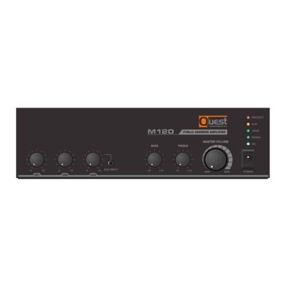
M120 Features The M120 mixer amplifiers are complete all-in-one mixer amplifier solutions for commercial and industrial applications. These low-cost units offer all the necessary features in a simple format. • Three (3) microphone inputs and two (2) line inputs ( , RCA and 3.5mm on the front panel). - Page 6 M120 M-Series – Front Panel Presentation [Figure 1.1 Front panel diagram] 1. Input Channel Volume – These three knobs determine the level of the sound sources connected to the inputs. 2. Tone Control – These two knobs adjust the overall frequency response of the system. They allow up to 10dB of cut/boost on the 100Hz and 10kHz bands.
- Page 7 M120 M-Series – Back Panel Presentation [Figure 1.2 Rear panel diagram] 1. Power Cable. 2. Speaker output connector – This 5-contact terminal block connector allows the use of 25V or 70V constant voltage loudspeakers, as well as low impedance loudspeakers of 4 or 8 ohms.
-
Page 8: Installation
Location: Take the unit out of its packaging (keep it for any return to the workshop). The M120 mixing amplifier can be installed in a standard 19” equipment rack or on a shelf. To install the unit in a standard 19” equipment rack, the optional RK- M3565 Rack Bracket Kit must be ordered at time of purchase. - Page 9 A simple way to represent a constant voltage is to divide the power in Watts of the amplifier by the number of loudspeakers used. For example, to connect ten loudspeakers to the output of an M120 amplifier, use a loudspeaker whose transformer provides a tap point of approximately 10 Watts.
- Page 10 M120 Installation Connecting sound sources Then connect the sound source to the terminal block input connectors on the back. If your console has balanced outputs, use balanced three-conductor connections and connectors (you can use unbalanced connections, but you'll get better sound quality and less noise if you use balanced connections).
-
Page 11: Wiring Guide
M120 Wiring Guide Wiring plans Choose the input connector and the appropriate cable for each source. We recommend the use of pre-assembled or professionally assembled 22-to-24-gauge balanced cables. Figure 2.1 shows the connection diagrams for the different connectors. RCA input connectors can also be used as unbalanced inputs. - Page 12 M120 Wiring Guide Wiring plans – Continued Choose the output connector and the appropriate cable for each source. For the amplifier output connectors, we recommend the use of pre-assembled or professionally assembled speaker cables of high quality and of sufficient gauge. You can use pluggable terminal blocks for your output connectors.
- Page 13 M120 Wiring Guide Speaker connections are shown in Figure 2.2 [Figure 2.2 How to connect speakers] WARNING: Never use the low impedance (4Ω / 8Ω) and high impedance (25V, 70V) outputs simultaneously. [Figure 2.3 Wrong connection]...
-
Page 14: Operations
M120 Operations Power On Press the power switch on the front to turn on the device. The Power indicator lights up, as well as the Protection indicator. The Protection indicator turns off after approximately five seconds (a click is then heard). -
Page 15: Music On Hold (Moh)
Operations Input Signals Gain Control. The Quest Commercial Mixer Amplifier can accept wide range and variable input signals thanks to the gain adjustment potentiometers. Adjust the gain potentiometer within a range of 44dB to accommodate different external equipment. Figure 3.2 shows the detail of input sensitivity. - Page 16 M120 Operations Using the Music on Hold (MoH) output to power a 2nd zone For use for 2 or more zones, the example below illustrates the installation that can be done when the unit is used in conjunction with a 2nd unit. The MOH connector of the first is used to power the second and so on.
-
Page 17: Block Diagram
Block Diagram M120... -
Page 18: Specifications
Specifications Performance M120 Input Sensitivity for full output at maximum gain Balanced Microphone inputs -50dB ± 3dB Unbalanced & AUX inputs -30dB ± 3dB Telephone Paging -21dB ± 3dB Frequency Response at 1watt from speaker out tap, 80Hz ~18kHz +1.5/-3dB...
Need help?
Do you have a question about the M120 and is the answer not in the manual?
Questions and answers