Table of Contents
Advertisement
Instruction Manual
D104016X012
Fisher
8590 Rotary Valve
™
Contents
. . . . . . . . . . . . . . . . . . . . . . . . . . . . . . . . . . .
. . . . . . . . . . . . . . . . . . . . . . . . . . . .
. . . . . . . . . . . . . . . . . . . . . . . . . . . . . . . .
. . . . . . . . . . . . . . . . . . . . . . . . . . . . . .
. . . . . . . . . . . . . . . . . . . . . . . . . . . . . . . . . . . .
. . . . . . . . . . . . . . . . . . . . . . . . . . . . . . . . . .
. . . . . . . . . . . . . . . . . . . . . . . . .
. . . . . . . . . . . . . . . . . . . . . . . . . . . . . . . .
. . . . . . . . . . . . . . . . . . . . . . . . . . . . . . . . . . .
. . . . . . . . . . . . . . . . . . . . . . . . . . . . . . . . . . .
Introduction
Scope of Manual
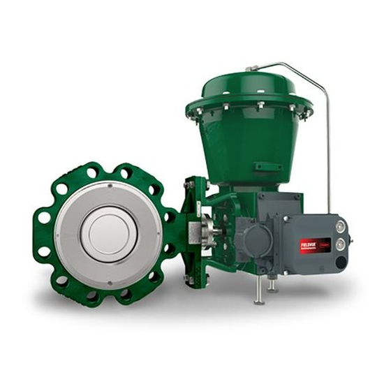
This instruction manual includes installation, maintenance, and parts information for the Fisher 8590 valve, NPS 3
through NPS 24 (figure 1). Refer to separate instruction manuals for information covering the power actuator and
accessories.
Do not install, operate, or maintain an 8590 valve without being fully trained and qualified in valve, actuator, and
accessory installation, operation, and maintenance. To avoid personal injury or property damage, it is important to
carefully read, understand, and follow all the contents of this manual, including all safety cautions and warnings. If you
have any questions about these instructions, contact your
proceeding.
Description
The Fisher 8590 High-Performance Butterfly Valve maintains tight shutoff, and can be specified for a wide range of
pressure and temperature conditions.
The 8590 valve is available in a lugged body design. A splined shaft can combine with a variety of
spring-and-diaphragm or pneumatic piston actuators. A square or keyed shaft can combine with a variety of
handlevers, handwheels, or pneumatic piston actuators. These combinations help make the 8590 valve a reliable,
high-performance butterfly valve for both throttling and on-off applications in the process industries.
www.Fisher.com
. . . . . . . . . . . . . . . . . . . . . . . . .
. . . . . . . . . . . . . . . . . . . . . . .
. . . . . . . . . . . . .
. . . . . . . . .
Figure 1. Fisher 8590 Valve with 2052 Actuator
and DVC6200 Digital Valve Controller
1
1
1
2
2
4
9
10
13
15
20
21
21
21
X0955-1
Emerson sales office
or Local Business Partner before
8590 Valve
June 2017
Advertisement
Table of Contents

Related Manuals for Fisher 8590


Summary of Contents for Fisher 8590
-
Page 1: Table Of Contents
NPS 24 (figure 1). Refer to separate instruction manuals for information covering the power actuator and accessories. Do not install, operate, or maintain an 8590 valve without being fully trained and qualified in valve, actuator, and accessory installation, operation, and maintenance. To avoid personal injury or property damage, it is important to carefully read, understand, and follow all the contents of this manual, including all safety cautions and warnings. -
Page 2: Specifications
Linear Disk Rotation Clockwise (CW) to close Educational Services For information on available courses for Fisher 8590 valves, as well as a variety of other products, contact: Emerson Automation Solutions Educational Services - Registration Phone: 1-641-754-3771 or 1-800-338-8158 E-mail: education@emerson.com emerson.com/fishervalvetraining... - Page 3 Instruction Manual 8590 Valve June 2017 D104016X012 Figure 2. Available Seal Configurations BACK-UP ANTI-EXTRUSION BACK-UP BODY BODY ANTI-EXTRUSION RING RING RING RING RETAINING SEAL RING RING SEAL RING RETAINING HIGH PRESSURE RESILIENT RING AT SHUTOFF INSERT VALVE DISK VALVE DISK...
-
Page 4: Installation
-325 to 1000 ENVIRO-SEAL Graphite -198 to 371 -325 to 700 1. The maximum temperature for a standard design of the 8590 valve is 538_C (1000_F). Contact your Emerson sales office or Local Business Partner for use in higher temperature applications. - Page 5 CAUTION 8590 disk rotation is counterclockwise to open (when viewed from the actuator side of the valve body, see figure 10) through 90 degrees of disk rotation. 6. With the disk in the closed position, install line flange gaskets, and insert the valve between the pipeline flanges.
- Page 6 Instruction Manual 8590 Valve June 2017 D104016X012 Lifting Guidelines Threaded holes for lifting are standard on the NPS 6 - 24 valve bodies. It is required that swivel hoists rings be used to lift the valve or valve and actuator assembly. An eyebolt cannot accommodate all lifting angles required to install or maintain the valve.
- Page 7 Instruction Manual 8590 Valve June 2017 D104016X012 Figure 3. Lifting Thread Locations (NPS 10 shown) LIFTING THREAD LIFTING THREAD Notes: Holes on opposite side are identical. NPS 10-24 only. Table 5. Valve Body Lifting Thread Information THREAD SIZE THREAD DEPTH...
- Page 8 WARNING An 8590 valve body is not necessarily grounded when installed in a pipeline. If the valve is used in a flammable or hazardous atmosphere or for oxygen service, an explosion could result due to a discharge of static electricity from the valve components.
-
Page 9: Maintenance
Instruction Manual 8590 Valve June 2017 D104016X012 Figure 5. Optional Shaft‐to‐Valve Body Bonding Strap Assembly Valves with ENVIRO‐SEAL packing systems will not require this initial re‐adjustment. See ENVIRO‐SEAL Packing System for Rotary Valves Instruction Manual (D101643X012) for packing instructions. If you wish to convert your present packing arrangement to ENVIRO‐SEAL packing, refer to the retrofit kits listed in the parts kit sub‐section on page 21 of... -
Page 10: Packing Maintenance
Packing may be PTFE V‐ring or graphite. An ENVIRO‐SEAL packing system is also available with the 8590 valve. To install the ENVIRO‐SEAL packing system in an existing valve, follow the instructions in the instruction manual included with the packing system (D101643X012). To remove packing parts in a valve with the ENVIRO‐SEAL packing system, follow the procedures for valves with the... - Page 11 Instruction Manual 8590 Valve June 2017 D104016X012 For valves with the ENVIRO‐SEAL packing system: Optimum performance of the ENVIRO‐SEAL packing system is obtained when the Belleville springs are tightened to their “target load.” The target load is the point where the springs are compressed to 85% of their maximum deflection, or nearly flat.
- Page 12 Instruction Manual 8590 Valve June 2017 D104016X012 3. Remove the packing flange nuts (key 27) and the packing flange (key 25) and pull out the packing follower (key 24). 4. Remove the anti‐blowout ring, if used (NPS 3-8) (key 23) from the drive shaft (key 7).
-
Page 13: Replacing The Seal Ring Assembly
Instruction Manual 8590 Valve June 2017 D104016X012 4. Remove the packing flange and spring pack assembly. The spring pack assembly consists of the spring stack and packing follower. The spring stack is retained on the packing follower by an O‐ring. Remove the anti‐blowout ring, if used (NPS 3-8) (key 23) from the drive shaft (key 7). - Page 14 Instruction Manual 8590 Valve June 2017 D104016X012 6. Remove the retainer gasket and clean the body gasket groove and retainer surface. 7. Remove the seal ring assembly (key 19). Soft Seal Installation 1. Locate the replacement seal ring (key 19) and note the shape of the ring. The ring is wider across one edge diameter and narrower across the other edge diameter as shown in figure 7.
-
Page 15: Replacing The Disk, Shafts, Or Bearings
Instruction Manual 8590 Valve June 2017 D104016X012 2. Place the retainer gasket (key 18) in the groove in the valve body. CAUTION The retainer gasket (key 18) is a thin graphite material. Take care to avoid damaging the gasket during handling. - Page 16 Instruction Manual 8590 Valve June 2017 D104016X012 CAUTION When removing the actuator in the following step, use a wheel puller to separate the actuator parts from the valve shaft. Do not drive the actuator parts off the valve shaft because this could damage valve trim components.
- Page 17 Instruction Manual 8590 Valve June 2017 D104016X012 10. If any of the bearings (keys 14 and 15) require replacement, remove them. 11. Clean the packing box. Assembly WARNING Do not lubricate bearings that will be used for oxygen service, or where the lubrication is incompatible with the process media.
- Page 18 Instruction Manual 8590 Valve June 2017 D104016X012 Figure 9. Orientation of NPS 3, 4, and 6 Thrust Bearings 1. If new bearings (keys 14 and 15) are required, install them in the valve body. Install the journal bearings (key 14) before installing the thrust bearing (key 15).
- Page 19 Instruction Manual 8590 Valve June 2017 D104016X012 CAUTION Once the final preload torque is applied, do not loosen or remove the blind flange nuts (key 5). If nut removal is necessary, a new gasket is required. Soft Seal Installation 1. Locate the replacement seal ring (key 19) and note the shape of the ring. The ring is wider across one edge diameter and narrower across the other edge diameter as shown in figure 7.
-
Page 20: Actuator Mounting
1. Screws must be lubricated to achieve proper preload. CAUTION 8590 valve disk rotation is counterclockwise to open (when viewed from the actuator side of the valve body, see figure 10). Rotating the disk (key 6) past the fully closed position will damage the seal ring (key 18). -
Page 21: Parts Ordering
Use only genuine Fisher replacement parts. Components that are not supplied by Emerson Automation Solutions should not, under any circumstances, be used in any Fisher valve, because they may void your warranty, might adversely affect the performance of the valve, and could cause personal injury and property damage. - Page 22 31 Mounting Cap Screw (NPS 3, 2 req'd, NPS 4-24, 4 req'd) *Recommended spare parts Figure 11. Fisher 8590, NPS 3-6, CL600 Valve Assembly NOTES: USE ONLY WITH PHOENIX III AND SOFT SEAL USE ONLY WITH NPS 3 SOFT SEAL AND PHOENIX III SEAL...
- Page 23 Instruction Manual 8590 Valve June 2017 D104016X012 Figure 12. Fisher 8590, NPS 8, CL600 Valve Assembly NOTES: USE ONLY WITH PHOENIX III AND SOFT SEAL PARTS NOT SHOWN: 32, 33, 34, 37, 38, 39, 41, 42 GE69177-A...
-
Page 24: D104016X012 June
Responsibility for proper selection, use, and maintenance of any product remains solely with the purchaser and end user. Fisher and ENVIRO-SEAL are marks owned by one of the companies in the Emerson Automation Solutions business unit of Emerson Electric Co. Emerson Automation Solutions, Emerson, and the Emerson logo are trademarks and service marks of Emerson Electric Co.
Need help?
Do you have a question about the 8590 and is the answer not in the manual?
Questions and answers