Table of Contents
Advertisement
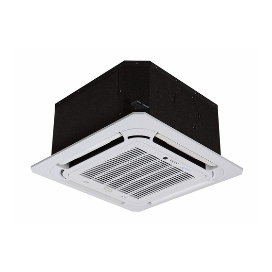
619R*C
Cassette Ductless System
Sizes 09 to 18
NOTE: The images in this manual are for illustration purposes
only. The actual model may differ slightly.
NOTE: Read the entire instruction manual before starting the
installation.
Installation Instructions
TABLE OF CONTENTS
. . . . . . . . . . . . . . . . . . . . . . . . . . . . . . . . . . . . . . .
. . . . . . . . . . . . . . . . . . . . . . . . . . . .
. . . . . . . . . . . . . . . . . . . . . . . . . . . . . . . .
. . . . . . . . . . . . . . . . . . . . . . . . . . . . . . .
. . . . . . . . . . . . . . . . . . . . . . . . . . . . . . . . . . . . . . . .
. . . . . . . . . . . . . . . . . . . . . . . . . . . . . .
. . . . . . . . . . . . . . . . . . . . . . . . .
. . . . . . . . . . . . . . . . . . . . . . . . . . .
. . . . . . . . . . . . . . . . . . . . . . . . . . .
. . . . . . . . . . . . . . . . . . . . . . .
. . . . . . . . . . . . . . . . . . . . . . . . .
PAGE
2
3
4
5
6
7
7
13
13
15
16
Advertisement
Table of Contents

Related Manuals for Bryant 619REQ012CBMA


Summary of Contents for Bryant 619REQ012CBMA
-
Page 1: Table Of Contents
619R*C Cassette Ductless System Sizes 09 to 18 Installation Instructions TABLE OF CONTENTS PAGE SAFETY CONSIDERATIONS ......PARTS LIST . -
Page 2: Safety Considerations
SAFETY CONSIDERATIONS WARNING Installing, starting up, and servicing air−conditioning equipment can be hazardous due to system pressures, electrical components, ELECTRICAL SHOCK HAZARD and equipment location (roofs, elevated structures, etc.). Failure to follow this warning could result in personal Only trained, qualified installers and service mechanics should injury or death. -
Page 3: Parts List
- Piping and the interconnecting wiring are field supplied. - Fig.1 is only a sketch. Different models may differ slightly. See Table 2 for the units covered in these installation instructions. Table 2—Indoor Units kBTUh V-Ph-Hz ID Model No. 208/230-1-60 619REQ009CBMA 208/230-1-60 619REQ012CBMA 208/230-1-60 619REQ018CBMA... -
Page 4: System Requirements
SYSTEM REQUIREMENTS Allow sufficient space for airflow and unit servicing. See Fig. 3 for the minimum required distances between the unit and the walls or ceilings. PIPING IMPORTANT: Both refrigerant lines must be insulated separately. S Minimum refrigerant line length between the indoor and outdoor units is 10 ft. (3 m). S Table 3 lists the pipe sizes for the indoor unit. -
Page 5: Dimensions − Indoor
DIMENSIONS − INDOOR Liquid side Gas side Body Drain hole Wiring connection port ( for Service ) E-parts box 4-Screw hole (for install panel) 4-install hanger 21.46(545) 10.24(260) 22.44(570) Drain pipe Outside Air Intake Wiring connection port 1.65(42) 2.67(68) Panel 1.97(50) 25.47(647) Fig. -
Page 6: Clearances − Indoor
CLEARANCES − INDOOR Fig. 3 - Cassette Unit Clearance... -
Page 7: Installation Tips
INSTALLATION TIPS Indoor Unit 2.8in(70mm) Installation locations include: S A location where no obstacles exist near the inlet and outlet areas. S A location which can bear the indoor unit’s weight is critical. 0.6in(15mm) 23.6in(600mm) 0.6in(15mm) S Do not install the indoor units near a direct source of heat such as direct sunlight or a heating appliance. - Page 8 INDOOR UNIT MAIN BODY INSTALLATION 3. Install the indoor unit temporarily. a. Attach the hanger bracket to the suspension bolt. Be sure 1. Prepare the ceiling opening needed for installation where to fix it securely by using a nut and washer from the upper applicable (for existing ceilings).
-
Page 9: Drain Piping Work
DRAIN PIPING WORK 1~1.5m Drain Piping Installation 300/11.8in 3~5ft Install the drain piping (see Fig. 10) and take steps to eliminate condensation. Improperly rigged piping could lead to leaks and eventually wet furniture and belongings. 1-1.5m 3~5ft Unit: mm Fig. 10 - Drain Piping Installation Fig. - Page 10 DRAIN PIPE TESTING Electrical Wiring 1. Remove the indoor unit control box lid. After the piping work is finished, check if the drainage flows smoothly. 2. Follow the “Wiring Diagram” label attached to the indoor unit’s control box lid to wire the outdoor unit, indoor unit Add approximately 1 liter of water gradually through the air and the wired remote controller.
-
Page 11: Installation Of The Decoration Panel
INSTALLATION OF THE DECORATION PANEL 3. After installing the decoration panel, ensure there is no space between the unit body and the decoration panel. Otherwise air Detach the intake grill may leak through the gap and cause dewdrops (see Fig. 20). 1. - Page 12 Grille Louver Motor Power. Grille Display 5 Pin Port 10 Pin Port CN40 Connector Used for Wired Remote Control with a 4 Pin Molex plug Wired Remote Controller Grille Display. (Available as Accessory) 10 pin Molex plug to be 5 Pin Molex plug to be connected to Control Board.
-
Page 13: Electrical Data
ELECTRICAL DATA Table 5—Electrical Data OPER. VOLTAGE OPER. VOLTAGE INDOOR FAN UNIT SIZE MAX FUSE CB AMP MAX FUSE CB AMP MAX / MIN* V-PH-HZ 0.146 0.061 Refer to outdoor unit installation instructions – 253 / 187 208-230/1/60 0.146 0.061 Indoor unit powered by the outdoor unit Indoor unit powered by the outdoor unit 0.146... -
Page 14: Wired Remote Controller
INSTALL ALL POWER, INTERCONNECTING Flare nut WIRING, AND PIPING TO INDOOR UNIT 1. Run interconnecting piping and wiring from the outdoor unit to the indoor unit. Copper tube 2. Connect wiring from the outdoor unit per the connection diagram (see Fig. 26). 3. -
Page 15: Start−Up
START−UP INDOOR UNIT 1. Do all the remote control buttons function properly? Test Operation 2. Do the display panel lights work properly? Perform a test operation after completing a gas leak and electrical 3. Does the air deflection louver function properly? safety check. -
Page 16: Troubleshooting
Outdoor IGBT temperature sensor error O (light) X (off) ☆ (flash) For additional diagnostic information, refer to the Service Manual. E2016 Bryant Heating & Cooling Systems D 7310 W. Morris St. D Indianapolis, IN 46231 Catalog No. II619RC-03 Edition Date: 08/16 Manufacturer reserves the right to discontinue, or change at any time, specifications or designs without notice and without incurring obligations.
Need help?
Do you have a question about the 619REQ012CBMA and is the answer not in the manual?
Questions and answers