Advertisement
Quick Links
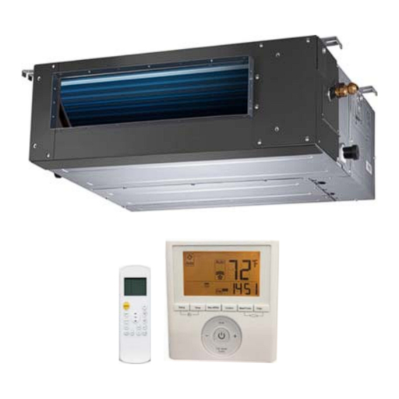
619R*D
Ducted Style Ductless System
Sizes 09 to 48
NOTE: Read the entire instruction manual before starting the
installation.
NOTE: Images are for illustration purposes only. Actual models
may differ slightly.
Installation Instructions
TABLE OF CONTENTS
SAFETY CONSIDERATIONS
PARTS LIST
. . . . . . . . . . . . . . . . . . . . . . . . . . . . . . . . . . . . . . .
SYSTEM REQUIREMENTS
WIRING
. . . . . . . . . . . . . . . . . . . . . . . . . . . . . . . . . . . . . . . . . . .
DIMENSIONS
. . . . . . . . . . . . . . . . . . . . . . . . . . . . . . . . . . . . . .
CLEARANCES
. . . . . . . . . . . . . . . . . . . . . . . . . . . . . . . . . . . . .
INSTALLATION LOCATION REQUIREMENTS
INDOOR UNIT INSTALLATION
FAN PERFORMANCES
. . . . . . . . . . . . . . . . . . . . . . . . . . . . . .
ELECTRICAL DATA
. . . . . . . . . . . . . . . . . . . . . . . . . . . . . . .
CONNECTION DIAGRAMS
WIRELESS REMOTE CONTROL INSTALLATION
START−UP
. . . . . . . . . . . . . . . . . . . . . . . . . . . . . . . . . . . . . . . .
TROUBLESHOOTING
. . . . . . . . . . . . . . . . . . . . . . . . . . . . . .
. . . . . . . . . . . . . . . . . . . . . . . . .
. . . . . . . . . . . . . . . . . . . . . . . . . . .
. . . . . . . . . .
. . . . . . . . . . . . . . . . . . . . . . .
. . . . . . . . . . . . . . . . . . . . . . . . .
. . . . . .
PAGE
2
3
4
4
5
6
7
7
9
17
17
19
20
21
Advertisement

Related Manuals for Bryant 619R D Series


Summary of Contents for Bryant 619R D Series
- Page 1 619R*D Ducted Style Ductless System Sizes 09 to 48 Installation Instructions TABLE OF CONTENTS PAGE SAFETY CONSIDERATIONS ......PARTS LIST .
- Page 2 SAFETY CONSIDERATIONS WARNING Installing, starting up, and servicing air−conditioning equipment can be hazardous due to system pressures, electrical components, ELECTRICAL SHOCK HAZARD and equipment location (roofs, elevated structures, etc.). Failure to follow this warning could result in personal Only trained, qualified installers and service mechanics should injury or death.
- Page 3 PARTS LIST Table 1—Parts List PART NO. NAME OF PART AIR OUTLET AIR INLET AIR FILTER ELECTRIC CONTROL CABINET WIRED CONTROLLER DRAIN PIPE (FIELD SUPPLIED) WIRELESS REMOTE Fig. 1 - Parts List Notes: - If the outdoor unit is higher than the indoor unit, prevent rain from flowing into the indoor unit along the connection pipe by creating a downward arc in the connection pipe before it enters the wall to the indoor unit.
- Page 4 SYSTEM REQUIREMENTS WIRING All wires must be sized per NEC (National Electrical Code) or Allow sufficient space for airflow and servicing unit. See Fig. 3 for CEC (Canadian Electrical Code) and local codes. Use the minimum required distances between the unit and the walls or Electrical Data table MCA (minimum circuit amps) and MOCP ceilings.
- Page 5 DIMENSIONS − INDOOR air inlet from rear side Air filter 4-install hanger Liquid side Ø 1 (25) Gas side Drain pipe Ø 1 (25) Drain pipe Test mouth & Test cover Ø 1 (25) Drain connecting pipe ( for pump ) Outside Air Intake Electric control box Air filter...
- Page 6 CLEARANCES − INDOOR Fig. 3 - Indoor Unit Clearances Table 5—Indoor Unit Clearance Capacity (Kbtu) 27.56 in. (70cm) 8.27 in. (21cm) 11.81 in. (30cm) 27.56 in. (70cm) 8.27 in. (21cm) 11.81 in. (30cm) 36.22 in. (92cm) 8.27 in. (21cm) 11.81 in. (30cm) 36.22 in.
- Page 7 5. Secure the unit in position with lock nuts and washers on INSTALLATION LOCATION both sides of the mounting bracket. Ensure the threaded REQUIREMENTS rod does not extend more than 2 in. below the mounting Indoor Unit brackets (see Fig. 5). S Confirm that the ceiling is able to support the weight of the unit.
- Page 8 4. Install the filter brackets to lock the filter in place. A150673 Fig. 12 - Condensate piping without a pump DRAIN PUMP AND DRAINAGE TEST Follow these steps to perform the test: 1. Remove the test cover by rotating it counter−clockwise as shown in Fig.
- Page 9 NOTE: In case the factory installed drain pump has to be disabled, place a Jumper (field supplied) on the Pin CN5 ”WATER” connector and disconnect the Pin CN13 ”PUMP” (see Fig 15). Disconnect Pin CN13 “PUMP” Add Jumper Pin CN5 “WATER”...
- Page 10 FAN PERFORMANCES AT VARYING STATIC PRESSURES (DUCTED UNITS) The static pressure of the indoor unit has been set in the factory according to Table 6. Table 6—Static Pressure Switch Static Pressure Range In. WG (Pa) Size 0.02 0.04 0.08 0.12 0.16 0-0.18 9 &...
- Page 11 STATIC PRESSURE CURVES SIZE 9...
- Page 12 STATIC PRESSURE CURVES SIZE 12...
- Page 13 STATIC PRESSURE CURVES SIZE 18...
- Page 14 STATIC PRESSURE CURVES SIZE 24...
- Page 15 STATIC PRESSURE CURVES SIZE 36...
- Page 16 STATIC PRESSURE CURVES SIZE 48...
- Page 17 ELECTRICAL DATA Table 8—Electrical Data INDOOR FAN MAX FUSE CB AMP UNIT SIZE V-PH-HZ 1.03 0.07 1.03 0.07 Refer to outdoor unit installation instructions – 0.83 0.12 Indoor unit powered by the outdoor unit 208-230/1/60 0.83 0.12 1.26 0.20 2.23 0.32 LEGEND FLA - Full Load Amps...
- Page 18 f. Apply a small amount of refrigerant oil to the flare INSTALL ALL POWER, INTERCONNECTING connection on the tubing. WIRING, AND PIPING TO INDOOR UNIT g. Align center of the pipes and/or service valve. 1. Run interconnecting piping and wiring from the outdoor unit to the indoor unit.
- Page 19 WIRELESS REMOTE CONTROL INSTALLATION Mounting Bracket (if installed on the wall) 1. Use the two screws supplied with control to attach the mounting bracket to the wall in a location selected by customer and within operating range. 2. Install batteries in the remote control. 3.
- Page 20 SYSTEM CHECKS CAUTION 1. Conceal the tubing where possible. 2. Make sure that the drain tube slopes downward along its UNIT DAMAGE HAZARD entire length. Failure to follow this caution may result in equipment 3. Ensure all tubing and connections are properly insulated. damage or improper operation.
- Page 21 TROUBLESHOOTING For ease of service, the systems are equipped with diagnostic code The indoor diagnostic display is a combination of flashing LEDs display LEDs on both the indoor and outdoor units. The outdoor on the display panel (IR Receiver). If possible, always check the diagnostic display consists of two LEDs (Red and Green) on the diagnostic codes displayed on the indoor unit first.
- Page 22 E2017 Bryant Heating & Cooling Systems D 7310 W. Morris St. D Indianapolis, IN 46231 Catalog No. II-619RD-05 Edition Date: 01/17 Manufacturer reserves the right to discontinue, or change at any time, specifications or designs without notice and without incurring obligations.
Need help?
Do you have a question about the 619R D Series and is the answer not in the manual?
Questions and answers