Table of Contents
Advertisement
SERVICE MANUAL
Ver. 1.3 2005. 09
With SUPPLEMENT-1
(9-927-910-81)
With SUPPLEMENT-2
(9-927-910-82)
AUDIO POWER SPECIFICATIONS
POWER OUTPUT AND TOTAL HARMONIC DISTORTION
With 3.2-ohm loads, both channels driven from 150 - 10,000 Hz; rated
1.3 W per channel-minimum RMS power, with no more than 10 % total
harmonic distortion in AC operation.
Other Specifications
CD player section
System
Compact disc digital audio system
Laser diode properties
Material: GaAlAs
Wave length: 780 nm
Emission duration: Continuous
Laser output: Less than 44.6 µW
(This output is the value measured at a distance of about 200 mm
from the objective lens surface on the optical pick-up block with 7
mm aperture.)
Spindle speed
200 r/min (rpm) to 500 r/min (rpm) (CLV)
Number of channels
2
Frequency response
20 - 20,000 Hz +1/–2 dB
Wow and flutter
Below measurable limit
9-927-910-13
Sony Corporation
Personal Audio Group
2005I02-1
© 2005.09
Published by Sony Engineering Corporation
Model Name Using
Similar Mechanism
Optical Pick-up Type
Tape Transport Mechanism Type
SPECIFICATIONS
Radio section
Frequency range
FM: 87.6 - 108 MHz
AM: 530 - 1,710 kHz
Antennas
FM: Telescopic antenna
AM: Built-in ferrite bar antenna
Cassette-corder section
Recording system
4-track 2 channel stereo
Fast winding time
Approx. 120 s (sec.) with Sony cassette C-60
Frequency response
TYPE I (normal): 70 - 10,000 Hz
General
Speaker
Full range: 10 cm dia., 3.2 ohms, cone type (2)
Outputs
Headphones jack (stereo minijack)
For 16 - 68 ohms impedance headphones
Power requirements
For CD radio cassette-corder:
120 V AC, 60 Hz
9 V DC, 6 size D (R20) batteries
Power consumption
AC 20 W
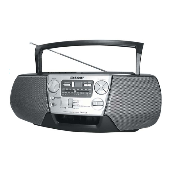
CD RADIO CASSETTE-CORDER
CFD-V5
US Model
CD Section
NEW
Tape Section
CFD-V17
DA-11
MF-V5-117
– Contimued on page 2 –
Advertisement
Table of Contents

Subscribe to Our Youtube Channel
Related Manuals for Sony CFD-V5


Summary of Contents for Sony CFD-V5
- Page 1 Laser diode properties 4-track 2 channel stereo Material: GaAlAs Fast winding time Wave length: 780 nm Approx. 120 s (sec.) with Sony cassette C-60 Emission duration: Continuous Frequency response Laser output: Less than 44.6 µW TYPE I (normal): 70 - 10,000 Hz...
-
Page 2: Table Of Contents
MARK ! ON THE SCHEMATIC DIAGRAMS AND IN THE PARTS 7. EXPLODED VIEWS LIST ARE CRITICAL TO SAFE OPERATION. REPLACE THESE COMPONENTS WITH SONY PARTS WHOSE 7-1. Front Cabinet Section ..........32 PART NUMBERS APPEAR AS SHOWN IN THIS MANUAL OR IN 7-2. -
Page 3: Servicing Notes
SECTION 1 SERVICING NOTES SAFETY CHECK-OUT NOTES ON HANDLING THE OPTICAL PICK-UP BLOCK OR BASE UNIT After correcting the original service problem, perform the following safety check before releasing the set to the customer : The laser diode in the optical pick-up block may suffer electro- Check the antenna terminals, metal trim, “metallized”... -
Page 4: General
SECTION 2 This section is extracted from GENERAL instruction manual. LOCATION AND FUNCTION OF CONTROLS REC PLAY REW FF STOP/EJECT PAUSE REPEAT RANDOM REPEAT Tape compartment CD compartment VOLUME PROGRAM Z PUSH OPEN/CLOSE OPR/BATT indicator TUNING MEGA BASS*1 .,> i (headphone) jack FUNCTION –... -
Page 5: Disassembly
SECTION 3 DISASSEMBLY The equipment can be removed using the following procedure. Cabinet (front) sub ASSY Control board, Connecter board Volume board, LCD board, Main board Cabinet (rear) Cabinet (upper) REC switch board, Mechanism deck, Optical pick-up section, CD motor board Belt, M601 (capstan/reel motor) Power board, Secondary board, Half battery board, battery board Note : Follow the disassembly procedure in the numerical order given. -
Page 6: Cabinet (Rear)
3-3. CABINET (REAR) 1 Screws 5 Screw +BVTP 3 × 12 +BVTP 3 × 12 3 Open the Lid (CD) 5 Screws +BVTP 3 × 10 2 Open the Holder assy, cassette by pressing STOP/EJECT button. Cabinet (Upper) STOP/EJECT button 4 Screw +BVTP 3 ×... -
Page 7: Volume Board, Lcd Board, Main Board
3-5. VOLUME BOARD, LCD BOARD, MAIN BOARD 8 Screws +BVTP 3 × 10 MAIN board 0 CNP301 7 Wire, parallel 5 CN701 (15 core) (optical pick-up) 4 S801 1 Wire, parallel (9 core) (CN706) LCD board 6 CNP302 Cabinet (Upper) VOLUME board 2 Screws +BVTP 3 ×... - Page 8 3-7. BELT, M601 (CAPSTAN / REEL MOTOR) 1 Screws +B 2.6 × 5 Mechanism deck 4 M601 3 Belt (Capstan/reel motor) – 8 –...
-
Page 9: Dial Pointer Installation
SECTION 4 DIAL POINTER INSTALLATION Note : Follow the installation procedure in the numerical order given. 1 Align the pointer with the groove of “cabinet (front) sub ASSY” and insert it as shown in the illustration. 2 Align knob (TU) with “cabinet (front) sub ASSY” and fasten the screw. Cabinet (front) sub ASSY 1 Pointer knob (Tu) -
Page 10: Adjustments
SECTION 5 ADJUSTMENTS 5-1. MECHANICAL ADJUSTMENTS Adjustment Location : Mechanism deck PRECAUTION 1. Clean the following parts with a denatured-alcohol-moistened swab : record/playback head pinch roller erase head rubber belts capstan 2. Demagnetize the record/playback head with a head demagne- tizer. - Page 11 VCO Adjustment • Repeat the procedures in each adjustment several times, and the frequency coverage and tracking adjustments should be finally Procedure : done by the trimmer capacitors. FM RF signal telescopic antenna generator terminal AM IF ADJUSTMENT Adjust for a maximum reading on level meter. 0.01µF 455kHz Carrier frequency : 98MHz...
- Page 12 CD SECTION How to put the set into CD Test Mode 1. Set the function switch to power off. 2. Set the function switch to CD while l key and x key pressing. The set is into CD test mode (88 is displayed). 3.
- Page 13 Adjustment Location : [MAIN BOARD] T1 : FM IF Adjustment (Component side) L3 : AM Tracking Adjustment RV1 : VCO Adjustment L4 : AM Frequency Coverage Adjustment L1: FM Tracking Adjustment L2 : FM Frequency Coverage Adjustment T2 : AM IF Adjustment CT4 : AM Frequency Coverage Adjustment [MAIN BOARD] CT2 : FM Frequency Coverage Adjustment...
-
Page 14: Diagrams
SECTION 6 DIAGRAMS 6-1. EXPLANATION OF IC TERMINALS IC702 LC78601E-MPB DIGITAL SIGNAL PROCESSOR, D/A CONVERTER, LCD DRIVE, SYSTEM CONTROL Pin No. Pin name Description DEFI DEF signal input. 3V/5V – Connect to ground. – Not used. VVSS – Not used (Ground terminal). ISET –... -
Page 15: Block Diagrams
CFD-V5 6-2. BLOCK DIAGRAMS Circuit Boards Location REC SWITCH board CONNECTOR board POWER board BATTERY board HALF BATTERY board SECONDARY board VOLUME board LCD board MOTOR board CONTROL board MAIN board • Signal path. : FM : AM : PB... -
Page 16: Printed Wiring Boards
CFD-V5 6-3. PRINTED WIRING BOARDS Refer to page 18 for Circuit Boards Location. Semiconductor ANT1 Location TELESCOPIC ANTENNA Ref. No. Location [CONNECTOR BOARD] [CONTROL BOARD] [MAIN BOARD] D302 D303 D304 S708 B C E S706 S705 RANDOM D308 PROGRAM REPEAT... -
Page 17: Schematic Diagram (Main Section 1/2)
CFD-V5 6-4. SCHEMATIC DIAGRAM – MAIN SECTION (1/2) – Refer to page 30 - 31 for IC Block Diagrams. Waveforms 3.7Vp-p 17.95 µ sec VOLT/DIV : 1 V AC Q301 C TIME/DIV : 5 µsec 34Vp-p 17.95 µ sec VOLT/DIV : 1 V AC... -
Page 18: Schematic Diagram (Main Section 2/2)
CFD-V5 6-5. SCHEMATIC DIAGRAM – MAIN SECTION (2/2) – Refer to page 30 - 31 for IC Block Diagrams. IC BLOCK DIAGRAMS IC1 CXA1238S Waveforms 28 27 26 25 24 23 22 21 FM FRONT-END 1.5–2.0Vp-p AM FRONT-END IC701 rj VOLT/DIV : 0.5 V AC... - Page 19 IC701 LA9250M-MPB LATCH RF AMP SLED SERVO SLEQ SPINDLE SERVO REF 1 F.SERVO &F.LOGIC T.SERVO &T.LOGIC IC703 LA6541L-TLM VREF MUTE 11kΩ 11kΩ LEVEL LEVEL SLIN SHIFT SHIFT DRIVER DRIVER DRIVER DRIVER 11kΩ LEVEL 11kΩ LEVEL SPIN SHIFT SHIFT REG OUT RESET REGULATOR RESET...
-
Page 20: Exploded Views
SECTION 7 EXPLODED VIEWS NOTE : • -XX, -X mean standardized parts, so they • The mechanical parts with no reference The components identified by mark 0 may have some difference from the original number in the exploded views are not or dotted line with mark 0 are critical one. -
Page 21: Rear Cabinet Section
7-2. REAR CABINET SECTION ANT1 T901 The components identified by mark 0 or dotted line with mark 0 are critical for safety. Replace only with part number specified. Ref. No. Part No. Description Remark Ref. No. Part No. Description Remark 3-043-835-01 CABINET (REAR) 3-031-540-81 HANDLE * 52... -
Page 22: Upper Cabinet Section
7-3. UPPER CABINET SECTION S801 LCD701 not supplied 103 108 Ref. No. Part No. Description Remark Ref. No. Part No. Description Remark * 101 A-3322-519-A MAIN BOARD, CONPLETE 3-922-112-41 DAMPER 4-960-167-01 SCREW (3X8) (DIA. 10), +WH 3-043-739-01 CABINET (UPPER) 3-031-560-01 SHAFT (MD) 1-792-640-11 WIRE, PARALLEL (FFC) (9 CORE) 3-031-541-61 BUTTON (REC) 4-951-620-01 SCREW (2.6X8), +BVTP... -
Page 23: Mechanism Deck Section (1)
7-4. MECHANISM DECK SECTION (1) (MF-V5-117) HRP901 HE901 Ref. No. Part No. Description Remark Ref. No. Part No. Description Remark 3-933-010-01 SPRING (S/P), TORSION * 162 3-008-587-01 SLIDER (STOP) 3-933-025-01 SPRING (P), TORSION * 163 3-008-591-01 SLIDER (PAUSE) 3-040-857-01 LEVER (P) 3-933-004-01 CLAW, REEL 3-933-024-01 ROLLER, PINCH * 165... -
Page 24: Mechanism Deck Section (2)
7-5. MECHANISM DECK SECTION (2) (MF-V5-117) S601 M601 Ref. No. Part No. Description Remark Ref. No. Part No. Description Remark 3-933-029-01 LEVER, ERASING PREVENTION 3-932-993-01 CHASSIS, OUTSERT 3-933-182-01 SPRING, CASSETTE 3-343-358-01 RING, RETAINING 3-932-995-01 GEAR (MID) 3-933-005-01 SPRING (CAM), COMPRESSION X-3371-667-1 CLUTCH ASSY 3-932-997-01 GEAR (CAM) 3-939-383-02 SPRING, COMPRESSION... -
Page 25: Cd Block Section
7-6. CD BLOCK SECTION (DA-11) Ref. No. Part No. Description Remark Ref. No. Part No. Description Remark A-3258-036-A CD BLOCK ASSY (DA-11) 3-931-379-31 RUBBER, VIBRATION PROOF (GREEN) 3-048-811-01 COVER, GEAR 3-931-379-21 RUBBER, VIBRATION PROOF (PINK) 3-048-741-01 GEAR, DRIVE 3-043-741-01 COVER (DA-11), CD 3-048-812-01 GEAR, MIDDLE 1-792-244-11 WIRE, PARALLEL (15 CORE) –... -
Page 26: Electrical Parts List
BATTERY CONNECTOR SECTION 8 ELECTRICAL PARTS LIST CONTROL HALF BATTERY MAIN NOTE : • Due to standardization, replacements in the • Items marked “ * ”are not stocked since they The components identified by mark 0 parts list may be different from the parts are seldom required for routine service. - Page 27 MAIN Ref. No. Part No. Description Remark Ref. No. Part No. Description Remark C154 1-126-925-11 ELECT 470uF C728 1-104-665-11 ELECT 100uF C155 1-136-165-00 MYLAR 0.1uF C729 1-104-665-11 ELECT 100uF C201 1-162-301-11 CERAMIC 0.0015uF 20% C730 1-161-494-00 CERAMIC 0.022uF C202 1-104-664-11 ELECT 47uF C203 1-127-883-21 CERAMIC...
- Page 28 MAIN Ref. No. Part No. Description Remark Ref. No. Part No. Description Remark <DIODE> 1-249-427-11 CARBON 6.8K 1/4W 1-249-427-11 CARBON 6.8K 1/4W 8-719-991-33 DIODE 1SS133T-77 1-249-421-11 CARBON 2.2K 1/4W 8-719-991-33 DIODE 1SS133T-77 1-249-429-11 CARBON 1/4W D302 8-719-991-33 DIODE 1SS133T-77 1-249-437-11 CARBON 1/4W D303 8-719-991-33 DIODE 1SS133T-77...
- Page 29 MAIN MOTOR POWER REC SWITCH Ref. No. Part No. Description Remark Ref. No. Part No. Description Remark R711 1-247-863-91 CARBON 1/4W <VIBRATOR> R712 1-247-863-91 CARBON 1/4W R713 1-249-431-11 CARBON 1/4W X701 1-577-253-11 VIBRATOR, CERAMIC (16.93MHz) ************************************************************** R716 1-249-439-11 CARBON 1/4W R717 1-249-419-11 CARBON 1.5K...
- Page 30 CFD-V5 Ver. 1.3 REC SWITCH SECONDARY VOLUME Ref. No. Part No. Description Remark Ref. No. Part No. Description Remark 1-677-112-11 VOLUME BOARD ************** ************** HARDWARELIST ************** <CAPACITOR> 7-685-647-79 SCREW +BVTP 3X10 TYPE2 N-S C123 1-115-870-11 ELECT 0.47uF 7-685-648-79 SCREW +BVTP...
- Page 31 CFD-V5 US Model SERVICE MANUAL 2000.09 SUPPLEMENT - 1 File this Supplement with the Service Manual. Subject : CHANGE OF BOARDS ELECTRICAL PARTS LIST (ECN-RCA01794) CHANGE OF BOARDS The main board and power board have been changed. Printed wiring board and schematic diagram of new type, and changed parts list are described in this Supplement-1.
- Page 32 CHANGED PARTS LIST EXPLODED VIEWS (Service Manual See page 32 to 34) Before Change Afrer Change Ref No. Part No. Description Part No. Description * 1-677-107-11 CONNECTOR BOARD CONNECTOR BOARD *1-679-067-11 * 1-677-106-11 CONTROL BOARD CONTROL BOARD *1-679-066-11 * 1-677-109-11 POWER BOARD POWER BOARD *1-679-069-11 * 1-677-108-11 SECONDARY BOARD...
- Page 33 CFD-V5 PRINTED WIRING BOARDS (Service Manual See page 20 to 21) ANT1 Semiconductor Location TELESCOPIC ANTENNA Ref. No. Location LCD BOARD CONNECTOR BOARD CN706 CNP707 MAIN BOARD D302 JW725 D303 JW705 B C E D304 JW735 D308 R792 FB701 JW729...
- Page 34 CFD-V5 SCHEMATIC DIAGRAM – MAIN SECTION (2/2) – (Service Manual See page 27 to 29) Refer to page 7 for Notes. Refer to page 7 for Waveforms. Refer to page 7 for IC Block Diagram. – 5 – – 6 –...
-
Page 35: Ic Block Diagram
Waveforms –MAIN SECTION (2/2) – 1.5–2.0Vp-p IC701 rj VOLT/DIV : 0.5 V AC TIME/DIV : 0.5 µsec 1.7Vp-p 16.9MHz IC702 y; VOLT/DIV : 0.5 V AC XOUT TIME/DIV : 20 nsec Note on Schematic Diagram: MAIN SECTION (2/2) • All capacitors are in µF unless otherwise noted. pF: µµF 50 WV or less are not indicated except for electrolytics and tantalums. - Page 36 POWER BOARD T901 POWER TRANSFORMER SECONDARY BOARD FB902 SECONDARY BOARD KH904 1-679-069- (11) MAIN BOARD BATTERY BOARD KH902 CNP907 Sony Corporation 2000I0212-1 9-927-910-81 Audio Entertainment Group Printed in Japan © 2000.9 – 8 – Published by PE General Engineering Dept.
- Page 37 CFD-V5 US Model SERVICE MANUAL 2001.03 SUPPLEMENT - 2 File this Supplement with the Service Manual. Subject : TEMPORARY CHANGE OF MECHANISM DECK MF-V5-117 t MF-V5-146 Applied Serial number : 1,390,001 to 1,540,000 (ECN-RCA01872) DIFFERENCE PARTS LIST EXPLODED VIEWS (Service Manual See page 33,34)
- Page 38 CFD-V5 Ver. 1.2 2001.03 (Service Manual See page 35) MECHANISM DECK SECTION (1) (MF-V5-146) M601 Ref. No. Part No. Description Remark Ref. No. Part No. Description Remark 3-933-843-01 BELT, MAIN 3-933-835-01 GEAR, FF 3-933-834-01 FLYWHEEL ASSY 3-915-796-01 REEL ASSY, TAKE UP...
- Page 39 CFD-V5 Ver. 1.2 2001.03 (Service Manual See page 36) HRP901 MECHANISM DECK SECTION (2) (MF-V5-146) HE901 S601 Ref. No. Part No. Description Remark Ref. No. Part No. Description Remark 3-915-751-01 LEVER, PAUSE BUTTON 3-933-818-01 PANEL, HEAD 3-915-750-01 LEVER, STOP BUTTON...
- Page 40 CFD-V5 REVISION HISTORY Clicking the version allows you to jump to the revised page. Also, clicking the version at the upper right on the revised page allows you to jump to the next revised page. Ver. Date Description of Revision 2000.04...
Need help?
Do you have a question about the CFD-V5 and is the answer not in the manual?
Questions and answers