Table of Contents
Advertisement
Quick Links
V I D E O
MIN
MAX
POWER
PHONES
LEVEL
PHONES
1. IMPORTANT SAFEGUARDS AND PRECAUTIONS ...................................................................... 1-1
2. FEATURES/3. SPECIFICATIONS .................................................................................................. 2-1
4. PART NAMES ................................................................................................................................. 4-1
5. MAINTENANCE CHECK ITEMS AND EXECUTION TIME ............................................................ 5-1
6. DISASSEMBLY AND REPLACEMENT OF MAIN PARTS ............................................................. 6-1
7. EXPLANATION OF MECHANISM .................................................................................................. 7-1
8. OPERATION OF PICKUP ............................................................................................................... 8-1
9. TEST MODE ................................................................................................................................... 9-1
10. TROUBLESHOOTING .................................................................................................................. 10-1
11. IC FUNCTION LIST ....................................................................................................................... 11-1
12. WIRING DIAGRAM ....................................................................................................................... 12-1
13. BLOCK DIAGRAMS ...................................................................................................................... 13-1
14. SCHEMATIC DIAGRAMS ............................................................................................................. 14-1
15. PRINTED WIRING BOARD ASSEMBLIES ................................................................................... 15-1
16. SEMICONDUCTOR LEAD IDENTIFICATION .............................................................................. 16-1
17. REPLACEMENT PARTS LIST ...................................................................................................... 17-1
18. PACKING OF THE SET ................................................................................................................ 18-1
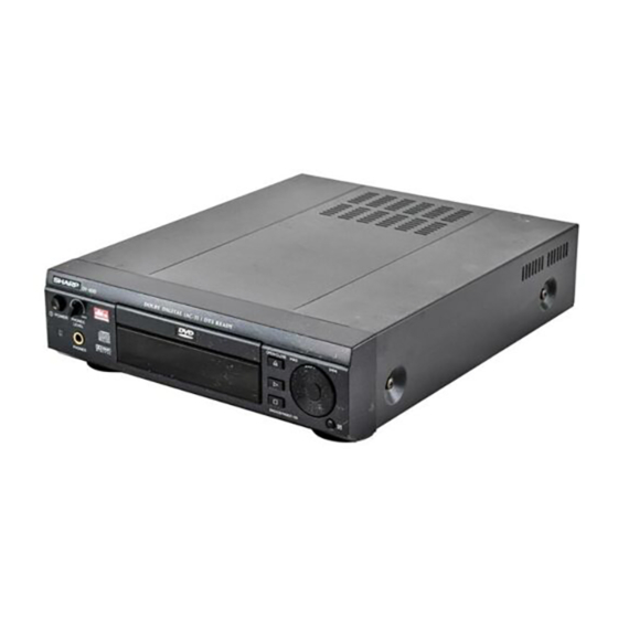
SERVICE MANUAL
DVD VIDEO PLAYER
DIGITAL
DIGITAL
GAMMA
S.PICTURE
OPEN/CLOSE
MODELS
In the interests of user-safety (Required by safety regula-
tions in some countries) the set should be restored to its
original condition and only parts identical to those specified
be used.
CONTENTS
SHARP CORPORATION
1
DV-660S
DV-660H
S59F9DV-600S/
DV-600S
DV-600H
Page
DV-600S
DV-600H
Advertisement
Table of Contents

Related Manuals for Sharp DV-600S


Summary of Contents for Sharp DV-600S
-
Page 1: Table Of Contents
DV-660S DV-600S DV-660H DV-600H SERVICE MANUAL S59F9DV-600S/ DVD VIDEO PLAYER DIGITAL DIGITAL GAMMA S.PICTURE DV-600S OPEN/CLOSE V I D E O POWER PHONES LEVEL PHONES DV-600H MODELS In the interests of user-safety (Required by safety regula- tions in some countries) the set should be restored to its original condition and only parts identical to those specified be used. -
Page 2: Important Safeguards And Precautions
DV-600S DV-600H 1. IMPORTANT SAFEGUARDS AND PRECAUTIONS... -
Page 3: Specifications
DV-600S DV-600H 2. FEATURES • Plays DVD, video CD and CD (Digital Audio) discs • Built-in Dolby Digital (AC-3) decoder supporting Dolby Pro Logic* decoding and Virtual Surround • MPEG 2-channel (STEREO) decoder (From AUDIO L/R) • MPEG MULTI digital out capability (5.1ch) •... -
Page 4: Part Names
DV-600S DV-600H 4. PART NAMES For details on the use of each control. -
Page 5: Maintenance Check Items And Execution Time
DV-600S DV-600H 5. MAINTENANCE CHECK ITEMS AND EXECUTION TIME MECHANICAL PARTS REGUIRING PERIODICAL INSPECTION Use the following table as a guide to maintain the mechanical parts in good operating condition. Maintained 1,000 hrs. 2,000 hrs. Parts Pickup Spindle Unit Sled Motor... -
Page 6: Disassembly And Replacement Of Main Parts
DV-600S DV-600H 6. DISASSEMBLY AND REPLACEMENT OF MAIN PARTS (A) 2 6-1. DISASSEMBLY (A) x2 1 1. Remove five screws (A), and remove the cabinet. Top Cabinet Note: When assembling it, tighten the screws in order of 1 - 2 . - Page 7 DV-600S DV-600H 6-2. REPLACEMENT OF MAIN PARTS Tray Decoration Panel <Disassembling and assembling procedure> · Removing the tray (emergency ejection) Removing the tray lock (set state) VIDEO Insert a thin plate into the hatching part, slowly move the it in the arrow direction so that the tray is moved out a little in the arrow direction.
- Page 8 DV-600S DV-600H 5. Disassembling the loading drive system (1) Remove the two M2 screws A . Remove relay gear 2 E . (2) Remove the tray pinion B . Remove the two M1.7 screws F . (3) Remove the relay gear 1 C together with the Remove the L motor G (with pulley) downward.
-
Page 9: Explanation Of Mechanism
DV-600S DV-600H 7. EXPLANATION OF MECHANISM (1) Tray loading mechanism When the tray loading motor rotates counterclockwise, motion is transmitted to the slide rack D through the intermediate gear 1 A , intermediate gear 2 B and tray pinion C , resulting in insignificant motion in the arrow direction. -
Page 10: Operation Of Pickup
DV-600S DV-600H 8. OPERATION OF PICKUP 8-1. CIRCUIT CONFIGURATION OF PICKUP The pickup unit reads signals from the disk, and the flexible cable is connected to the board. The following signals flow through the cable. 8-2. EQUIVALENT CIRCUIT OF PICKUP 8-3. - Page 11 DV-600S DV-600H...
- Page 12 DV-600S DV-600H...
- Page 13 DV-600S DV-600H...
- Page 14 DV-600S DV-600H...
- Page 15 DV-600S DV-600H 10-1...
- Page 16 DV-600S DV-600H 10-2...
- Page 17 DV-600S DV-600H 10-3...
-
Page 18: Ic Function List
DV-600S DV-600H 11. IC FUNCTION LIST 11-1. IC201 MC44724A DIGITAL VIDEO ENCODER Pin No. Terminal name Operation function CVBS/Cb/B1 Analog composite video signal output or Cb or B signal output current drive (positive) CVBS/Cb/B1 Analog composite video signal output or Cb or B signal output current drive (negative) - Page 19 DV-600S DV-600H • Block Diagram Y/G 1Vdd copy Sync_generator CVBS/Cb/B 1Vdd protection DVdd 30 37, 57 C/Cr/R 1Vdd 38, 56 DVss Y/G 1 CGMS, CC_gen WSS gen Y/G 1 CVBS/Cb/B 1 H, V off_set CVBS/Cb/B 1 39~46 DVIA [7:0] C/Cr/R 1...
- Page 20 DV-600S DV-600H • Block Diagram 11-3. IC303 IX1517GE RF SIGNAL PROCESSOR Pin No. Terminal name Operation function Terminal DC Voltage(TYP.) Remarks – GND terminal. – P2TP TE+input (CD) P2TN TE–input (CD) LDO2 O Drive ouput – MDI2 Monitor input –...
- Page 21 DV-600S DV-600H Pin No. Terminal name Operation function Terminal DC Voltage(TYP.) Remarks O RF total addition output 2.2[V] Boost adjustment When EQB is raised, the boost increases. Frequency adjustment When EQF is raised, shift to the high frequency side occurs.
- Page 22 DV-600S DV-600H 11-5. IC402 IX1474GE DEM/ECC (DVD) Pin No. Terminal name Operation function Remarks DPCK1 Signal processing reference clock input. 0.5-3.3Vp-p Feedback resistor built in. DVDD3 – Digital power. (3.3V) For logic cell SVCK1 Servo reference clock input. (Oscillation circuit input terminal) 3.3V-I/F Feedback...
- Page 23 DV-600S DV-600H Pin No. Terminal name Operation function Remarks MOEN External RAM output permission signal. MWEN External RAM read/write selection. DVSS – Digital power. (0V) For logic cell DVDD3 – Digital power. (3.3V) For logic cell External RAM address bus.
- Page 24 DV-600S DV-600H 11-6. IC501 IX1539GE FLASH Symbol Type Name and function Byte selection address: When the device is in the x8 mode, the low or high order byte is Input selected. It is not used in the x16 mode. (If BYTE# is high, DQ input circuit does not operate.)
- Page 25 DV-600S DV-600H 11-7. IC504 IX1478GE SYSCON Port D Port E /IRQ7 /IRQ6 /IRQ5 /IRQ4 EXTAL XTAL STBY H8S/2000 CPU WDTOVF Interruption controller /ø DMAC ROM * /HWR /LWR /LCAS/WAIT/BFEQO /BACK /BREQ /CS0 /CS1 /CS2 /CS3 /SCK1 /CAS /SCK0 /RxD1 /CS7/IRQ3...
- Page 26 DV-600S DV-600H 11-9. IC507 BR93L46F EEPROM Terminal Terminal name In/Output Function – Power – All input/output reference voltage, 0V Input Tip select input Input Sirial clock input Input Start bit, operation code, address and serial data input OCNT Output Serial data output, READY/BUSY internal status indication output •...
- Page 27 DV-600S DV-600H Terminal Terminal name In/Output Function MRST Input Reset signal – Digital GND – Digital power +3.3V PXDO (0) Output Pixel data output PXDO (1) Output 8-bit parallel video data conforming to ITU-R BT.601 and BT.656 standard (Cb/Y/Cr/Y) PXDO (2)
- Page 28 DV-600S DV-600H 11-11. IC512 IX1535GE HOST I/F Terminal Terminal name In/Output Function – Power +3.3V HADR0 Input CPU Address bus HADR1 Input CPU Address bus HADR2 Input CPU Address bus Input CPU Tip select Input CPU Write signal Input CPU Read signal...
- Page 29 DV-600S DV-600H Pin1~15 ..There is a possibility of simultaneous change. Operating frequency: Approx. 10 MHz Pin18~47 ..There is a possibility of simultaneous change.(Static signal) Operating frequency: Approx. 1 MHz Pin50~57 ..There is almost no possibility of simultaneous change.
- Page 30 DV-600S DV-600H Microcomputer interface terminal list Pin No. Pin name Type Direction Function Microcomputer interface HTYPE = L It works as HACK# (acknowledge) output terminal for connection to HACK# Motorola type microcomputer. (HR/W#) It can be used as the weight terminal for connection to the general pur pose microcomputer.
- Page 31 DV-600S DV-600H Microcomputer / CD·subcode interface terminal list Pin No. Pin name Type Direction Function Microcomputer interface / CD·subcode interface When 16-bit bus width is selected, (HWID=low) It works as the microcomputer data bus of 9th bit. When 8-bit bus width is selected, (HWID=high)
- Page 32 DV-600S DV-600H Video/OSD interface terminal list Pin No. Pin name Type Direction Function Video interface · OSD interface Video8 register = 0 Color difference signal output terminal of 2th bit. (OSDPEL2) (3-S) Video8 register = 1 It works as the OSD pallet data input terminal of 2rd bit.
- Page 33 DV-600S DV-600H DVD-DSP interface terminal list Pin No. Pin name Type Direction Function DVD-DSP interface DVDERR Data error input for DVD-DSP connection. DVDSOS Sector start input for DVD-DSP connection. DVDVALID Data valid input for DVD-DSP connection. DVDSTRB Data strobe input for DVD-DSP connection.
- Page 34 DV-600S DV-600H 11-13. IC602 IX1537GE 16M SDARM Terminal Terminal Name Name Input Function System Clock Active on the positive going edge to sample all inputs. Chip Select Disables or enables device operation by masking or enabling all inputs except CLK. CKE and L(U)DQM Clock Enable Masks system clock to freeze operation from the next clock cycle.
-
Page 35: Motor Driver
DV-600S DV-600H 11-14. IC702 BA6796FP MOTOR DRIVER Pin No. Terminal name Operation function Pin No. Terminal name Operation function OPOUT Ope amp. output terminal CH2-OUT- CH2 Negative output terminal CH4-IN CH4 Input terminal CH2-OUT+ CH2 Positive output terminal CH4-IN’ CH4 Gain adjustment input terminal... - Page 36 DV-600S DV-600H 11-15. IC707 IX1473GE SERVO PROCCESSOR Pin No. Terminal name Operation function Remarks – Digital ground terminal. Bit clock (1.4122MHz) output terminal. AOUT Audio data output terminal. DOUT Digital out output terminal. MBOB Buffer memory over signal output terminal. Over: “H”...
- Page 37 DV-600S DV-600H Pin No. Terminal name Operation function Remarks Tracking equalizer output terminal. VREF – Analog reference power terminal. RFGC RF amplitude adjustment control signal output terminal. Output of 3-pole PWM signal. (PWM carrier = 88.2 kHz) TEBC Tracking balance control signal output terminal.
- Page 38 DV-600S DV-600H Pin No. Terminal name Operation function Remarks BUS3 – Digital + power terminal. – Digital ground terminal. BUCK Microcomputer interface clock input terminal. Schmidt input /CCE Microcomputer interface chip enable signal input terminal. Schmidt input BUS0 to 3 is active in “L” state.
- Page 39 DV-600S DV-600H 11-16. IC801 PCM1716E AUDIO D/A CONVERTER Pin No. Terminal name Operation function LRCIN LRCK clock input (fs) Data input BCKI Bit clock input for data. CLKO System clock buffered output. Connection of crystal oscillator or external clock input.
- Page 40 DV-600S DV-600H 11-17. IC5001 IMN12510F FL DRIVER Terminal Terminal Name Name In/Output Function Power supply terminal Input VDD: +5V±0.5V VSS: 0V FLP driver power Input VPP: VDD –35V The voltage to be supplied to the SEG 0 to 7, DGT 0 to 7 pull-down resistor is applied.
-
Page 41: Wiring Diagram
DV-600S DV-600H 12. WIRING DIAGRAM 12-1... -
Page 42: Block Diagrams
DV-600S DV-600H 13. BLOCK DIAGRAMS 13-1. MAIN BLOCK DIAGRAM 13-1... - Page 43 DV-600S DV-600H 13-2...
- Page 44 DV-600S DV-600H 13-2. POWER BLOCK DIAGRAM 13-3...
- Page 45 DV-600S DV-600H 13-4...
-
Page 46: Schematic Diagrams
DV-600S DV-600H 14. SCHEMATIC DIAGRAMS 14-1. MAIN (1) CIRCUIT SCHEMATIC DIAGRAM LOCATION MAP: (1/4) 14-1... - Page 47 DV-600S DV-600H LOCATION MAP: (2/4) 14-2...
- Page 48 DV-600S DV-600H LOCATION MAP: (3/4) 14-3...
- Page 49 DV-600S DV-600H LOCATION MAP: (4/4) 14-4...
- Page 50 DV-600S DV-600H 14-2. MAIN (2) CIRCUIT SCHEMATIC DIAGRAM LOCATION MAP: (1/4) 14-5...
- Page 51 DV-600S DV-600H LOCATION MAP: (2/4) 14-6...
- Page 52 DV-600S DV-600H LOCATION MAP: (3/4) 14-7...
- Page 53 DV-600S DV-600H LOCATION MAP: (4/4) 14-8...
- Page 54 DV-600S DV-600H 14-3. TERMINAL/21-PIN EURO-SCART CIRCUIT SCHEMATIC DIAGRAM 14-9...
- Page 55 DV-600S DV-600H å AND SHADED COMPONENTS=SAFETY RELATED PARTS 14-10...
- Page 56 DV-600S DV-600H 14-4. DISPLAY/OPERATE/VOLUME CIRCUIT SCHEMATIC DIAGRAM 14-11...
- Page 57 DV-600S DV-600H 14-12...
-
Page 58: Printed Wiring Board Assemblies
DV-600S DV-600H 15. PRINTED WIRING BOARD ASSEMBLIES 15-1. MAIN P.W.B. Componet Side 15-1... - Page 59 DV-600S DV-600H 15-2...
- Page 60 DV-600S DV-600H 15-2. MAIN P.W.B. Wiring Side 15-3...
- Page 61 DV-600S DV-600H 15-4...
- Page 62 DV-600S DV-600H 15-3. TERMINAL/OPERATE/VOLUME P.W.B. TERMINAL OPERATE 15-5...
- Page 63 DV-600S DV-600H VOLUME 15-6...
- Page 64 DV-600S DV-600H 15-4. DISPLAY/21-PIN EURO-SCART P.W.B. DISPLAY 15-7...
- Page 65 DV-600S DV-600H 21-PIN EURO-SCART 15-8...
-
Page 66: Semiconductor Lead Identification
DV-600S DV-600H 16. SEMICONDUCTOR LEAD IDENTIFICATION IC301 RH-iX1461GEZZ IC702 IC707 VHiBA6796FP-1 RH-iX1473GEZZ IC801 VHiPCM1716E-1 IC201 X601 VHiMC44724A-1 RCRSC0031GEZZ IC2302 X702 VHiNJM2286M-1 RCRSC0035GEZZ IC303 IC2006 IC2005 RH-iX1517GEZZ IC401 IC704 RH-iX1484GEZZ RH-iX1531CEZZ IC2002 IC2003 VHiNJM2268M-1 IC402 IC501 IC2303 IC2304 RH-iX1474GEZZ RH-iX1539GEZZ VHiNJM2267M-1... -
Page 67: Replacement Parts List
DUNTK5766TE6A - Main PWB Unit(DV-600S) — FL501 RFiLC0196GEZZ Filter, FiLC0196GE DUNTK5766TE6B - Main PWB Unit(DV-600H) — DUNTK5667TEV3 - Terminal PWB Unit(DV-600S) — COILS DUNTK5667TEV4 - Terminal PWB Unit(DV-600H) — L201 VP-NM470K2R0N Peaking, 47µH DUNTK5668TEV3 - Display PWB Unit(DV-600S) — L202 VP-NM100KR42N Peaking, 10µH... - Page 68 DV-600S DV-600H Ref. No. Part No. Description Code Ref. No. Part No. Description Code DUNTK5766TE6A(DV-600S) C347 VCKYCY1HB222K 2200p 50V Ceramic DUNTK5766TE6B(DV-600H) C348 VCKYCY1HB222K 2200p 50V Ceramic MAIN PWB UNIT(Continued) C349 VCKYCY1HB102K 1000p 50V Ceramic C353 VCEAPF0JW476M 6.3V Electrolytic C354 VCKYCY1CB104K...
- Page 69 DV-600S DV-600H Ref. No. Part No. Description Code Ref. No. Part No. Description Code DUNTK5766TE6A(DV-600S) C7005 VCKYCY1HB103K 0.01 50V Ceramic DUNTK5766TE6B(DV-600H) MAIN PWB UNIT(Continued) RESISTORS R201 VRS-CY1JF820J 1/16W Metal Oxide AA C605 VCKYCY1CB104K 16V Ceramic R202 VRS-CY1JF820J 1/16W Metal Oxide AA...
- Page 70 DV-600S DV-600H Ref. No. Part No. Description Code Ref. No. Part No. Description Code DUNTK5766TE6A(DV-600S) R597 VRS-CY1JF472J 4.7k 1/16W Metal Oxide AA DUNTK5766TE6B(DV-600H) R603 VRS-CY1JF102J 1/16W Metal Oxide AA MAIN PWB UNIT(Continued) R630 VRS-CY1JF000J 1/16W Metal Oxide AA R632 VRS-CY1JF000J...
- Page 71 DV-600S DV-600H Ref. No. Part No. Description Code Ref. No. Part No. Description Code DUNTK5766TE6A(DV-600S) DUNTK5667TEV3(DV-600S) DUNTK5766TE6B(DV-600H) DUNTK5667TEV4(DV-600H) MAIN PWB UNIT(Continued) TERMINAL PWB UNIT R884 VRS-CY1JF100J 1/16W Metal Oxide AA INTEGRATED CIRCUITS R885 VRS-CY1JF100J 1/16W Metal Oxide AA IC2002 VHiNJM2268M-1...
- Page 72 DV-600S DV-600H Ref. No. Part No. Description Code Ref. No. Part No. Description Code DUNTK5667TEV3(DV-600S) R2010 VRS-CY1JF102J 1/16W Metal Oxide AA DUNTK5667TEV4(DV-600H) R2012 VRS-CY1JF750J 1/16W Metal Oxide AA TERMINAL PWB UNIT(Continued) R2013 VRS-CY1JF750J 1/16W Metal Oxide AA R2015 VRS-CY1JF102J 1/16W Metal Oxide AA...
- Page 73 DV-600S DV-600H Ref. No. Part No. Description Code Ref. No. Part No. Description Code DUNTK5667TEV3(DV-600S) RESISTORS DUNTK5667TEV4(DV-600H) JP6601 VRS-CY1JF000J 1/16W Metal Oxide AA TERMINAL PWB UNIT(Continued) R5001 VRS-CY1JF333J 33k 1/16W Metal Oxide AA R5009 VRS-CY1JF102J 1/16W Metal Oxide AA MISCELLANEOUS PARTS...
- Page 74 DV-600S DV-600H Ref. No. Part No. Description Code Ref. No. Part No. Description Code CAPACITOR R2308 VRD-RA2BE102J 1/8W Carbon R2309 VRS-CY1JF102J 1/16W Metal Oxide AA C6661 VCKYCY1HF103Z 0.01 50V Ceramic R2310 VRS-CY1JF682J 6.8k 1/16W Metal Oxide AA R2311 VRS-CY1JF682J 6.8k 1/16W Metal Oxide AA...
- Page 75 DV-600S DV-600H Ref. No. Part No. Description Code Ref. No. Part No. Description Code CABINET PARTS SUPPLIED ACCESSORIES GCABA3115AJSJ Top Cabinet å QACCB0016TAZZ AC Power Cord(600H) å JBTN-2861AJSD Power Button QACCK0002TAZZ AC Power Cord(600S) NSFTZ0202AJFW Shaft QCNW-1688TAZZ S-Video Cord CDECQ1959TEV1...
- Page 76 DV-600S DV-600H MECHANISM EXPLODED VIEW Ref. No. Part No. Description Code Ref. No. Part No. Description Code Dry Coading Dry Coading Grease Grease 1-10 Grease 1-11 1-12 1-13 å Caution When touching the pickup, Grease • wear an earth band to p revent breakage by static electricity.
- Page 77 DV-600S DV-600H CABINET EXPLODED VIEW Ref. No. Part No. Description Code Ref. No. Part No. Description Code 17-11...
- Page 78 DV-600S DV-600H FRONT PANEL PARTS EXPLODED VIEW Ref. No. Part No. Description Code Ref. No. Part No. Description Code 501-12 501-11 501-4 501-7 501-2 501-2-1 501-13 501-3 501-11 501-5 501-6 501-10 501-9 501-8 17-12...
-
Page 79: Packing Of The Set
(Remote Control Unit) SPAKX1006AJZZ (Packing Add.) ÷ : PS SSAKA0160CEZZ (Polyethylene Bag, Accessories) ÷ : PS å QACCK0002TAZZ (DV-600S) (AC Cord) QCNW-7581GEZZ (Video/Audio Cable) TiNS-3614AJZZ (DV-600S) TiNS-3613AJZZ (DV-600H) (Operation Manual) SPAKL0030GEZZ (Handle) SPAKC4110AJZZ (DV-600S) SPAKC4109AJZZ (DV-600H) (Packing Case) Not Replacement Items 18-1... - Page 80 Code Ref. No. Part No. Description Code COPYRIGHT C 1999 BY SHARP CORPORATION ALL RIGHTS RESERVED. No part of this publication may be reproduced, stored in a retrieval system, or transmitted in any form or by any means, electronic, mechanical, photocopying, recording, or otherwise, without prior written permission of the publisher.
Need help?
Do you have a question about the DV-600S and is the answer not in the manual?
Questions and answers