Table of Contents
Advertisement
Advertisement
Table of Contents

Related Manuals for Fluke 279 FC


Summary of Contents for Fluke 279 FC
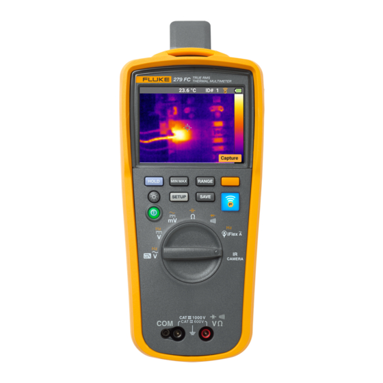
- Page 1 Test Equipment Depot - 800.517.8431 - 99 Washington Street Melrose, MA 02176 - TestEquipmentDepot.com 279 FC True-rms Thermal Multimeter Users Manual March 2016 ©2016 Fluke Corporation. All rights reserved. All product names are trademarks of their respective companies.
- Page 2 LIMITED WARRANTY AND LIMITATION OF LIABILITY Each Fluke product is warranted to be free from defects in material and workmanship under normal use and service. The warranty period is three years and begins on the date of shipment. Parts, product repairs, and services are warranted for 90 days. This warranty extends only to...
-
Page 3: Table Of Contents
Fluke Connect™ Wireless System........ - Page 4 279 FC Users Manual Temperature Units..............11 Image Memory Management.
- Page 5 Contents (cont.) Maintenance................33 Multimeter Care .
- Page 6 279 FC Users Manual...
- Page 7 List of Tables Table Title Page Symbols ..............4 Setup Menu Functions .
- Page 8 279 FC Users Manual...
- Page 9 Fluke Connect™ ........
- Page 10 279 FC Users Manual viii...
-
Page 11: Introduction
Introduction The Multimeter supports the Fluke Connect™ Wireless The 279 FC True-rms Thermal Multimeter (the Multimeter or System (may not be available in all regions). Fluke Connect™ Product) is a digital multimeter with an integrated thermal is a system that wirelessly connects your Multimeter with an imaging camera. -
Page 12: How To Contact Fluke
279 FC Users Manual Safety Information A Warning identifies conditions and procedures that are dangerous to the user. A Caution identifies conditions and procedures that can cause damage to the Product or the equipment under test. XW Warning To prevent possible electrical shock, fire, or personal injury: Carefully read all instructions. - Page 13 True-rms Thermal Multimeter Safety Information Examine the case before you use the Product. Measure a known voltage first to make sure that • • Look for cracks or missing plastic. Carefully the Product operates correctly. look at the insulation around the terminals. •...
- Page 14 This product contains a Lithium-ion battery. Do not mix with the solid waste stream. Spent batteries should be disposed of by a qualified recycler or hazardous materials handler per local regulations. Contact your authorized Fluke Service Center for recycling information.
-
Page 15: Fluke Connect™ Wireless System
Fluke Connect™ Wireless System Fluke Connect™ Wireless System Set Up for Fluke Connect App The Fluke Connect app works with Apple and Android mobile The Multimeter supports the Fluke Connect™ Wireless products. The app is available for download from the Apple System (may not be available in all regions). -
Page 16: Before You Start
On your smartphone, go to Settings > Bluetooth. Multimeter. Verify that Bluetooth is turned on. Warning Go to the Fluke Connect App and in the list of connected To prevent possible electrical shock, fire, or Fluke tools, select 279 FC. personal injury: You can now take, save, and share measurements with the •... -
Page 17: On/Off
True-rms Thermal Multimeter Before You Start On/Off Push to turn on or turn off the Multimeter. Hanging Strap The Multimeter includes a hanging strap that allows you to hang your Multimeter so you can take measurements hands- free. See Figure 2. Display Information Hazardous Voltage The hazardous voltage warning X shows on the display... -
Page 18: Battery Charge
279 FC Users Manual Battery Charge The Multimeter is packaged with the battery pack at <30 % charge. Before first use, make sure the battery pack is fully Warning charged. The battery pack must be removed and charged outside of the Multimeter. See Figure 3. - Page 19 True-rms Thermal Multimeter Before You Start Figure 3. Battery Charge...
-
Page 20: Setup Menu
279 FC Users Manual Setup Menu Table 2. Setup Menu Functions The Setup Menu includes these functions: • on/off for the audible beeper • on/off for automatic backlight dimming • on/off for automatic power off (battery save) • unit selection for temperature measurements •... -
Page 21: Beeper
Auto Off is always disabled when MIN MAX AVG Push (Select) to open the submenu. recording or a Fluke Connect session is in progress. Use to set as OFF or ON. Push (Exit) to close the Setup Menu. -
Page 22: Image Memory Management
For information about the calibration of your Multimeter, see memory, the Multimeter will prompt you to overwrite the first the 279 FC True-rms Thermal Multimeter Calibration Manual. (oldest) image before you can continue to save. Or, you can Device Information go to the Setup Menu to delete all the images in memory. -
Page 23: Inputs
True-rms Thermal Multimeter Before You Start Inputs Rotary Switch and Pushbuttons Table 3 is a list of the inputs for the Multimeter. Use the rotary switch to select a function on the Multimeter. The position of the rotary switch can have more than one Table 3. - Page 24 279 FC Users Manual Table 4. Rotary Switch Positions Function AC voltage measurement from 0.060 V to 1000 V. Push to measure frequency from 2 Hz to 999.9 Hz. Push again to measure Volts/Hertz. DC voltage from 0.001 V to 1000 V.
- Page 25 True-rms Thermal Multimeter Before You Start Table 5. Pushbuttons Button Switch Position Function Not related to switch Turn on and turn off the Multimeter. position Set the Multimeter to manual range and scroll through each range. Push and hold for ...
-
Page 26: Ir Camera Mode
The IR Camera mode uses the ironbow palette. The display shows a center point marker for the temperature With the Fluke Connect app you can expand your use of these measurement. Temperature units of measurement are images. See Set Up for Fluke Connect App on page 5 for selected in the Setup Menu. -
Page 27: Basic Measurements
True-rms Thermal Multimeter Basic Measurements Basic Measurements Basic measurements and tests: • AC and DC Voltage Measurements. See Figure 4. XW Warning • Volts/Hertz Ratio. See Figure 6. To prevent possible electrical shock, fire, or • Resistance Measurements. See Figure 7. personal injury, disconnect power and discharge all high-voltage capacitors before •... - Page 28 279 FC Users Manual Volts AC Volts DC Millivolts DC Volts AC Volts DC Millivolts DC iFlex iFlex iFlex Figure 4. AC and DC Voltage Measurements...
-
Page 29: Volts/Hertz Ratio
True-rms Thermal Multimeter Basic Measurements Volts/Hertz Ratio The Multimeter can show the ratio of volts to frequency of the ac signal. See Figure 6. When the Multimeter is set to the Volts/Hz function, the voltage range is set to manual. If the voltage increases to a value larger than the range, the Multimeter shows in the display. -
Page 30: Resistance Measurements
279 FC Users Manual Resistance Measurements XW Warning To prevent possible electrical shock, fire, or personal injury, disconnect power and discharge all high-voltage capacitors before you measure resistance, continuity, capacitance, or a diode junction. The Multimeter sends a small current through the circuit for resistance measurements. -
Page 31: Capacitance Measurements
True-rms Thermal Multimeter Basic Measurements Capacitance Measurements XW Warning To prevent possible electrical shock, fire, or personal injury, disconnect power and discharge all high-voltage capacitors before you measure resistance, continuity, capacitance, or a diode junction. The Multimeter makes a capacitance measurement by charging a capacitor with a known current, measures the resulting voltage, then calculates the capacitance. -
Page 32: Continuity Test
279 FC Users Manual Continuity Test XW Warning To prevent possible electrical shock, fire, or personal injury, disconnect power and discharge all high-voltage capacitors before you measure resistance, continuity, capacitance, or a diode junction. The continuity test uses a beeper that sounds when a closed circuit is sensed. -
Page 33: Ac Current Measurements
True-rms Thermal Multimeter Basic Measurements AC Current Measurements To measure: Connect the iFlex Current Probe to the input on the XW Warning Multimeter. See Figure 10. To prevent possible electrical shock, fire, or personal injury: Center the conductor perpendicularly inside the flexible probe area. - Page 34 279 FC Users Manual AC Current Current Frequency iFlex iFlex Figure 10. AC Current Measurements...
-
Page 35: Diode Test
True-rms Thermal Multimeter Basic Measurements Diode Test In a circuit, a good diode has a forward-bias measurement of 0.5 V to 0.8 V. A reverse-bias measurement includes the XW Warning resistance of other pathways between the probes. To prevent possible electrical shock, fire, or A short beep sounds if the diode is good (<0.85 V). - Page 36 279 FC Users Manual Reverse Bias Forward Bias Reverse Bias Good Diode Good Diode Good Diode Good Diode Bad Diode Bad Diode Bad Diode Bad Diode iFlex OPEN OPEN BEEP BEEP and Shorted and Shorted Figure 11. Diode Test...
-
Page 37: Frequency Measurements
True-rms Thermal Multimeter Basic Measurements Frequency Measurements Hints for frequency measurements: A frequency measurement is a count of the number of times • If a measurement shows 0 Hz or is not stable, the input an ac voltage or current signal passes through a threshold signal can be below or near a trigger level. - Page 38 279 FC Users Manual AC/DC Voltage Frequency AC Current Frequency AC/DC Voltage Frequency AC Current Frequency iFlex iFlex iFlex HzAC Figure 12. Frequency Measurement...
-
Page 39: Measurement Features
True-rms Thermal Multimeter Measurement Features Measurement Features To start a MIN MAX AVG record session: Make sure the Multimeter is set to the correct This section is about the Multimeter features you can use for measurement function and on the correct range. measurements. -
Page 40: Display Hold
279 FC Users Manual To exit and erase the MIN, MAX, and AVG values, push Display Hold for 1 second or turn the rotary switch. XW Warning To see the other recorded values (minimum and To prevent possible electrical shock, fire, or average), push . -
Page 41: Auto Range And Manual Range
True-rms Thermal Multimeter Measurement Features Auto Range and Manual Range AC Zero Input Behavior of True-rms Meters The Multimeter has auto range and manual range. Average responding meters can accurately measure only pure sinewaves. A true-rms meter can accurately measure When you turn on the Multimeter, it is set to auto range and distorted waveform signals. -
Page 42: Smartview® Software
279 FC Users Manual ® SmartView Software Firmware Updates To download firmware: ® Firmware updates are available through SmartView desktop software installed on your PC. Open SmartView ® on the PC. To download Smartview: Connect a USB 2.0 (High Speed) cable to the Multimeter. -
Page 43: Ir Image Management
True-rms Thermal Multimeter Maintenance Maintenance IR Image Management Warning You can manage your IR images through SmartView ® desktop To prevent a possible electrical shock, fire, or software installed on your PC. Use SmartView to download personal injury: and delete the IR images from the Multimeter. •... -
Page 44: Multimeter Care
Replacement parts and accessories are shown in Table 6 and delicate anti-reflective coating. Figure 13. • Do not clean too vigorously as this can damage For more information about parts and accessories, see How the anti-reflective coating. to Contact Fluke on page 2. - Page 45 Battery Door Assembly (includes tilt stand) 4693466 Test Lead Set TL175 Alligator Clip, Black AC175 Alligator Clip, Red 279 FC Quick Reference Guide 4694103 279 FC Safety Information 4717467 9-inch Hanger Strap TPAK80-4-8001 Hanging Clip TPAK80-2003 ...
- Page 46 279 FC Users Manual Figure 13. Accessories and Replacement Parts...
-
Page 47: Specifications
True-rms Thermal Multimeter Specifications Specifications Maximum Voltage between any Terminal and Earth Ground ....... . . 1000 V Temperature Operating . - Page 48 279 FC Users Manual Safety General ..........IEC 61010-1: Pollution Degree 2 Measurement .
-
Page 49: Detailed Specifications
True-rms Thermal Multimeter Detailed Specifications Detailed Specifications For all specifications: Accuracy is specified for 1 year after calibration, at operating temperatures of 18 °C to 28 °C, with relative humidity at 0 % to 90 %. Accuracy specifications take the form of ±([% of Reading] + [Number of least significant digits]). AC Voltage Measurements [2][3][4] Measurement... -
Page 50: Dc Voltage, Continuity, Resistance, Diode Test, And Capacitance Measurements
279 FC Users Manual DC Voltage, Continuity, Resistance, Diode Test, and Capacitance Measurements Function Range Resolution Measurement 600.0 mV 0.1 mV 0.09 % + 2 6.000 V 0.001 V 60.00 V 0.01 V 0.09 % + 2 600.0 V 0.1 V... -
Page 51: Ac Current With Iflex I2500
True-rms Thermal Multimeter Detailed Specifications AC Current with iFlex i2500 Range ........... 1.0 A ac to 2500 A ac Resolution 1.0 A to 999.9 A . -
Page 52: Input Characteristics
279 FC Users Manual Input Characteristics Common Mode Overload Input Impedance Function Rejection Ratio Normal Mode Rejection Protection (nominal) (1 kΩ unbalance) 1100 V rms >10 MΩ <100 pF >120 dB at dc, 50 Hz or 60 Hz >60 dB at 50 Hz or 60 Hz ... -
Page 53: Infrared Camera
Image Transfer ........ - Page 54 279 FC Users Manual...
Need help?
Do you have a question about the 279 FC and is the answer not in the manual?
Questions and answers