Table of Contents
Advertisement
Quick Links
Advertisement
Table of Contents

Subscribe to Our Youtube Channel
Related Manuals for Roc Hobby WACO


Summary of Contents for Roc Hobby WACO
- Page 1 OPERATING MANUAL f!l ·...
-
Page 2: Safety Precautions And Warnings
.,,.. """ ROCHOBBY Friendly Reminder � Thank you for purchasing a ROC HOBBY product. Our goal is to provide high quality products and offer great customer service. If you have any problems with your product or want to offer suggestions for improvements (such as plane design, packaging, building instructions, etc.), please feel free to contact... -
Page 3: Table Of Contents
Index 1. Photo of Unassembled Kit 2. Kit Contents 3. Spare Parts List/ Item Numbers 4. Illustration of Spare Parts 5. Kit Inspection 6. Electrical Parameters 7. Charging the Flight Battery 8. Low Voltage Cut Off (LVC) 9. Airplane Assembly: 10. -
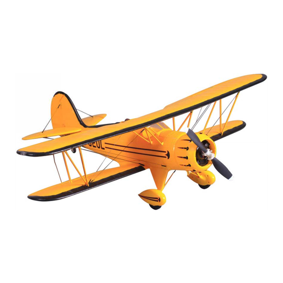
Page 4: Photo Of Unassembled Kit
7. lnterplane struts and cabane Spare Parts List Replacement parts for the ROCHOBBY WACO are available using the order numbers in the Spare parts list that follows. The fastest, most economical service can be provided by your hobby dealer or mail-order company. -
Page 5: Illustration Of Spare Parts
KE-110. MotorBoard KE-111. Spinner (Propeller hub and spinner) KE-112. Propeller(11*7) KE-113. Cabane Yellow/Red KE-114. lnterwing strut Yellow/Red KE-115. Pushrods KE-116. MotorShaft KE-117. Motor(D3536-KV850) KE-118. 9g Servo (With arm) KE-119. ESC(35A/4ASBEC) KE-120. Battery(11.1v, 1800mAh,25C) KE-121. Decal sheet Yellow/Red The illustration of the spare parts �? 1111'"' -�... -
Page 6: Kit Inspection
Kit Inspection J Before beginning assembly, inspect all of the parts for any damage or defects. If any parts are missing or defective or damaged, or if you need assistance with setup and assembly, please feel free to contact the ROC TEAM. Please write down the name and item number of the parts when you are reporting a damaged, defective or missing item. -
Page 7: Electrical Parameters
Charging the Flight Battery Electrical Parameters Parameter Type Unit Working Voltage Input Power Work Temperature Store Temperature - 20 Charging Stop Voltage 4. 19 4.20 4.21 Charging Current 1000 Balancing Current Activate Current Using Steps: 1. Connect the charger to adapter with enough voltage and wattage, then the Power LED will turn on; Connect 2S/3S battery pack to the corresponding balance port (Do not connect two battery packs at the same time), then the Charge LED will flicker (1 Hz) and start charging. -
Page 8: Charging The Flight Battery
Charging the Flight Battery Protection Function 1. Reverse connection protection of input Reverse connection protection of output Short circuit protection of output Over voltage protection of output Troubleshooting 1. Power LED does not shine-Adapter isn't connected correctly. Please check the polarity and reconnect adapter. -
Page 9: Low Voltage Cut Off (Lvc)
Low voltage cut off (LVC) When a Li-Po is discharged below 3V per cell, it will not hold a charge. The ESC protects the flight battery from over-discharge using Low Voltage Cutoff. Before the battery charge decreases too much, LVC removes power from motor in two ways: (1) Reduces power - ESC reduces motor power (recommended), (2) Hard cutoff - ESC instantly cuts motor power when the pre-set Low Voltage Protection Threshold value is reached. -
Page 10: Installing The Lower Wing
OSBY Airplane Assembly J Installing the lower wing 5. The aileron control horns are contained in 1. Insert the Leads of the main wing from the the spare parts bag with the linkage rod. hole on the bottom of the wing mounting bay to the cockpit hatch before mounting the lower wing into the bay. -
Page 11: Main Landing Gear Installation
'BBY Main Landing Gear Installation 3. Secure the plate using the provided self 1. Fully insert the landing gear strut into the tapping screws. slot on the landing gear base . • 2. Place the landing gear securing fairing Mount the top wing plate in place, facing the right direction. - Page 12 C1BBY Airplane Assembly J 3. Secure the strut using two self tapping 5. Secure the strut using two self tapping screws screws with the LED wire slot toward the as shown in the picture, repeat this step for leading edge of the wing. Repeat this step mounting the other cabane.
-
Page 13: Arranging The Led Wires
Airplane Assembly 8. Turn the plane over, so the bottom of the plane faces up and secure the top wing to the ca bane using self tapping screws. (Screws: PA2.0*8 4PCS) • 2. Secure the wire into the slot using the included wire tape covering. - Page 14 Airplane Assembly 2. Insert the left (port) side stabilizer into place. 4. Secure the wing joiner to the bottom of Make sure the elevator joiners interlock the elevator. (PA2.0*8 1 PCS) to each other before fully sliding the stabilizer into place. �;...
-
Page 15: Installing The Receiver And Battery
Airplane Assembly Installing the Receiver and Battery 1. Plug the leads to the receiver as shown 3. Open the battery hatch cover by raising in the diagram. the tape at the front, install the battery with • the cable toward the rear of the plane . Receiver Aileron Channel-1... - Page 16 Airplane AssemblyJ 2. Put the Z-bend end of the of the aileron Tip: Snap the clevis shut and locked, then make sure to secure the it with the pushrods into the desired servo control horn hole. It is a tight fit and should allow rubber O ring to keep it from coming the linkage to move just slightly within loose.
-
Page 17: Preflight
The motor has an optional brake setting. The ESC comes with the brake switched off and we recommended that the WACO be flown with the brake off. However, the brake could be accidentally switched on if the motor battery is connected to the ESC while the throttle stick is set at full throttle. -
Page 18: The Transmitter And Model Setup
Preflight The transmitter and model setup CAUTION: To prevent personal injury, DO NOT install the propeller assembly onto the motor shaft while testing the control surfaces . DO NOT arm the ESC and do not turn on the transmitter until the Transmitter Manual instructs you to do so. Tips: Make sure all control sticks on your radio are in the neutral position (rudder, elevator, ailerons) and the throttle in the OFF position. - Page 19 Preflight 2. Make sure all servo arms are fully vertical. If not, adjust the servo arm by using the trim function on your radio. Note: For computerized transmitters, use the servo/channel sub-trim feature to make each servo arm fully vertical. The standard hole settings for linkage connections are shown by the black arrows in the the diagram below.
-
Page 20: Check The Control Throws
OSBY Preflight Check the control throws : The suggested control throw settings for RocHOBBY Waco are as follows (Dual rate settings): High Rate Low Rate Elevator 15mm up/down 10mm up/down Aileron 18mm up/down 12mm up/down Rudder 12mm left/right 8mm left/right Tips: For the first flight, fly the model in low rate. -
Page 21: Flying Wires And Pilots Installation
'l3BY Preflight 2. Verify the completed stabilizer flying wire 2. Snap the clevis into the eyelet on bottom linkage. of top wing aileron control horn and secure it using the rubber O ring. '· • 3. Verify the completed wing flying wire 3. -
Page 22: Center Of Gravity (Cg)
Preflight Check the C.G. (Center of Gravity) Center of Gravity When balancing your model, slide the motor battery forward or backwards as necessary so the model is level or slightly nose down. This the correct balance point for your model. After the first flights, the CG position can be adjusted for your personal preference. -
Page 23: Preflight Recommendations
' "1 � c� � '/11:4 Preflight Recommendations Find a suitable flying site Find a flying site clear of buildings, trees, power lines and other obstructions. Until you know how much area will be required and have mastered flying your plane in confined spaces, choose a site which is at least the size of two to three football fields - a flying field specifically for R/C planes is best. - Page 24 While applying power slowly, steer to keep the model straight, the model should accelerate quickly. As the model gains flight speed, you will want to climb at a steady and even rate. Waco will climb out at a nice angle of attack (AOA).
-
Page 25: Trouble Shooting
Trouble Shooting Problem Possible Cause Solution Aircraft will not - Lower throttle stick and throttle - ESC is not armed. respond to the trim to lowest settings. Throttle channel is reversed. throttle but responds Reverse throttle channel on to other controls. transmitter. -
Page 26: Ama
OSBY AMA J If you are not already a member of the AMA, please join, The AMA is the governing body of model aviation and membership provided liability insurance coverage, protects modelers' rights and interests and is required to fly at most R/C sites. Academy of Model Aeronautics 5151 East Memorial Drive Muncie, IN 47302-9252... - Page 27 OSBY Exceptions: 1. Free Flight fuses or devices that burn producing smoke and are securely attached to the model aircraft during flight. 2. Officially designated AMA Airshow Teams(AST) are authorized to use devices and practices as defined within the Team AMA Program Document (AMA Document #718) 3.
- Page 28 Email:info@rochobby.com Http ://www.rochobby.com MADE IN CHINA...
Need help?
Do you have a question about the WACO and is the answer not in the manual?
Questions and answers