Table of Contents
Advertisement
WARNING: FIRE OR EXPLOSION HAZARD
Failure to follow safety warnings exactly could result in serious injury, death, or property damage.
- Do not store or use gasoline or other flammable vapors and liquids in the vicinity of this or any
other appliance.
- WHAT TO DO IF YOU SMELL GAS
• Do not try to light any appliance.
• Do not touch any electrical switch; do not use any phone in your building.
• Leave the building immediately
• Immediately call your gas supplier from a neighbor's phone. Follow the gas supplier's
instructions.
• If you cannot reach your gas supplier, call the fire department.
-
Installation and service must be performed by a qualified installer, service agency or the gas supplier.
A barrier designed to reduce the risk of burns from
the hot viewing glass is provided with this appliance
and shall be installed for the protection of children
and other at-risk individuals.
This appliance may be installed in an aftermarket, permanently located, manufactured home
(USA only) or mobile home, where not prohibited by local codes.
This appliance is only for use with the type of gas indicated on the rating plate. A conversion
kit is supplied with the appliance.
INSTALLER: Leave this manual with the appliance.
CONSUMER: Retain this manual for future reference.
Travis Industries, Inc.
Copyright 2016, T.I.
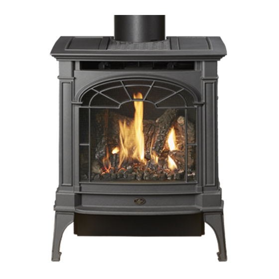
NorthField GSR2
Deluxe
Owner's Manual
HOT GLASS WILL CAUSE
BURNS
DO NOT TOUCH GLASS
UNTIL COOLED
NEVER ALLOW CHILDREN
TO TOUCH GLASS
12521 Harbour Reach Dr., Mukilteo, WA 98275
$10.00
Built-In Direct Vent Stove
Natural Gas or Propane
Residential or Mobile
French language manuals at travisindustries.com
Manuels de Français langue à travisindustries.com
4160713
Tested and Listed by
ANSI Z21.88-2014
CSA 2.33-2014
Home
www.travisproducts.com
100-01442
Advertisement
Table of Contents

Related Manuals for Lopi NorthField GSR2 Deluxe


Summary of Contents for Lopi NorthField GSR2 Deluxe
- Page 1 NorthField GSR2 Deluxe Owner’s Manual WARNING: FIRE OR EXPLOSION HAZARD Failure to follow safety warnings exactly could result in serious injury, death, or property damage. - Do not store or use gasoline or other flammable vapors and liquids in the vicinity of this or any other appliance.
-
Page 2: Introduction
Introduction Introduction We welcome you as a new owner of a Lopi Northfield GSR2 stove. In purchasing a Northfield you have joined the growing ranks of concerned individuals whose selection of an energy system reflects both a concern for the environment and aesthetics. The Northfield is one of the finest home heaters the world over. -
Page 3: Table Of Contents
Table of Contents Introduction .............. 2 Before You Begin ........... 34 Important Information ..........2 Remote Set-Up ............35 Listing Details ............2 Verify the Switch is on “REMOTE” ...... 35 Heating Specifications ..........6 Synchronize the Transmitter to the IFC .... - Page 4 Safety Precautions Failure to follow all of the requirements may result in property damage, bodily injury, or even death. Young children should be carefully supervised when they are in the same room as the appliance. Toddlers, young children and others may be susceptible to accidental contact burns.
- Page 5 Safety Precautions Safety Warnings (continued) Because this heater can be controlled by a thermostat there is a possibility of the heater turning on and igniting any items placed on or near the appliance. Light the heater using the built-in igniter. Do not use matches or any other external device to light your heater.
-
Page 6: Heating Specifications
Specifications Features: Installation Options: Ember Fyre™ Burner for "Wood Fire" Look Freestanding Stove Works During Power Outages (battery backup system) Horizontal or Vertical Vent High Efficiency Residential or Mobile Home Remote Control with Thermostat Includes Decorative Fireback Straight or Corner Placement Includes High-Tech Blower for Heat Distribution Bedroom Approved Convenient Operating Controls... -
Page 7: Installation Warnings
Installation (for qualified installers only) Installation Warnings Failure to follow all of the requirements may result in property damage, bodily injury, or even death. This heater must be installed by a qualified installer who has gone through a training program for the installation of direct vent gas appliances. -
Page 8: Packing List
Installation (for qualified installers only) Packing List Additional Items Required • Remote Control Vent (see “Venting Requirements” for details) • Propane Conversion Kit Gas Line Equipment (shutoff valve, pipe, etc.) • Log Set LP Units Require GSR Stepper Motor •... -
Page 9: Stove Clearances
Installation (for qualified installers only) Installation Hints If converting to LP, convert the appliance prior to installation. Install the logs last - they are fragile. When determining the location of the stove, locate the wall studs (for horizontal penetrations) and ceiling trusses (for vertical penetrations). -
Page 10: Top To Rear Vent Modification
Installation (for qualified installers only) Top to Rear Vent Modification NOTE: If using the rear vent configuration, make sure to review vent configuration before proceeding. Remove the cast iron stove top and flue cover to access the vent components (see page 28) NOTE: Use a magnetic-tipped nutdriver on these screws - take care to prevent the screws from... -
Page 11: Top To Rear Vent Modification (Continued)
Installation (for qualified installers only) Top to Rear Vent Modification (continued) Install the inner flue assembly and exhaust cover plate. Make sure the attached gaskets are in place and form an air-tight seal. NOTE: Install the flue assembly with the diffuser to the bottom. -
Page 12: Heater Placement Requirements
Installation (for qualified installers only) Heater Placement Requirements • Heater must be installed on a level surface capable of supporting the heater and vent • Due to the high temperature, the heater should be located out of traffic and away from furniture and draperies. -
Page 13: Gas Line Installation
Installation (for qualified installers only) Gas Line Installation The gas line must be installed in accordance with all local codes, if any; if not, follow current ANSI Z223.1 or NFPA 54 in the USA and the current CGA B149 in Canada. The heater and gas control valve must be disconnected from the gas supply piping during any pressure testing of that system at test pressures in excess of 1/2 psig (3.45 kPA). -
Page 14: Vent Requirements
Installation (for qualified installers only) Vent Requirements • The gas appliance and vent system must be vented directly to the outside of the building, and never be attached to a chimney serving a separate solid fuel or gas-burning appliance. Each direct vent gas appliance must use its own separate vent system. -
Page 15: Approved Vent Configurations
Installation (for qualified installers only) Approved Vent Configurations Overview This appliance has several components used to control the flow of intake air and exhaust gases. Depending upon vent configuration, you may be required to adjust the intake restrictor, exhaust restrictor, diffuser and/or install the intake dampers and extender plate. -
Page 16: Exhaust Restrictor
Installation (for qualified installers only) Exhaust Restrictor NOTE: Refer to the vent configuration (pages 17 to 22) to determine the correct restrictor position. Loosen these two screws on the exhaust restrictor. Slide the restrictor to the correct restrictor position (see the illustration below). -
Page 17: Rear Vent Configurations With Horizontal Termination And No Rise
Installation (for qualified installers only) Rear Vent Configurations with Horizontal Termination and No Rise • Use 8” Diameter Vent with a 6-5/8” to 8” adapter (increaser). We recommend using the minimum vent kit from Travis Industries (SKU 96200311). This kit contains the following components used to vent the stove through a typical exterior wall: -- 6-5/8”... -
Page 18: Rear Vent Configurations With Horizontal Termination And 1' Min. Rise
Installation (for qualified installers only) Rear Vent Configurations with Horizontal Termination and 1’ Min. Rise • Use 6-5/8” Diameter Vent • Horizontal sections require a ¼” (6mm) rise every 12” (305mm) of travel. • Maximum of one (1) 45° or 90° horizontal elbow may be used (see illustration). •... -
Page 19: Rear Vent Configurations With Vertical Termination
Installation (for qualified installers only) Rear Vent Configurations with Vertical Termination • Use 6-5/8” Diameter Vent • Horizontal sections require a ¼” (6mm) rise every 12” (305mm) of travel. • A maximum of three (3) elbows may be used (e.g.: one 90° and two 45° or three 90°). •... -
Page 20: Rear Vent Configuration Vented Into Stove With Co-Linear Adapter
Installation (for qualified installers only) Rear Vent Configuration Vented into Stove with Co-Linear Adapter • Attach the Co-Linear adapter directly to the back of the stove. Use two (2) 3” UL 441 or 1775 gas liners to vent the appliance through a code-conforming masonry or metal (zc) stove. All clearances to combustibles must be met and the flex vent must be vented through a non-combustible stove chimney. -
Page 21: Top Vent Configuration With Vertical Termination
Installation (for qualified installers only) Top Vent Configuration with Vertical Termination • Use 6-5/8” Diameter Vent • Horizontal sections require a ¼” (6mm) rise every 12” (305mm) of travel. • A maximum of four (4) 45° or 90° elbows may be used. Of these elbows, only one (1) may be a horizontal elbow (see illustration). -
Page 22: Top Vent Configuration With Horizontal Termination
Installation (for qualified installers only) Top Vent Configuration with Horizontal Termination • Use 6-5/8” Diameter Vent • Horizontal sections require a ¼” (6mm) rise every 12” (305mm) of travel. • A maximum of four (4) 45° or 90° elbows may be used. Of these elbows, only one (1) may be a horizontal elbow (see illustration). -
Page 23: Vent Termination Requirements (See Illustration Below)
Installation (for qualified installers only) Vent Termination Requirements (see illustration below) Venting terminals shall not be recessed into a wall or siding. Minimum 9" (229mm) clearance from any door or window Roof Minimum 12" (305mm) above any grade, veranda, porch, deck or balcony Surface Minimum 1"... -
Page 24: Class A Chimney Conversion Kit (Top Vent Configuration Only)
Installation (for qualified installers only) Class A Chimney Conversion Kit (top vent configuration only) Simpson Duravent provides a conversion kit for those wishing to use an existing wood stove chimney to vent this direct vent stove. The illustration below gives an overview of this type of installation. See the instructions included with the kit for details. -
Page 25: Interior Masonry Chimney Conversions (Top Vent Configuration Only)
Installation (for qualified installers only) Interior Masonry Chimney Conversions (top vent configuration only) • Follow the requirements and use the equipment listed in the illustration below to install this appliance into an interior masonry chimney. • Maximum vertical rise is 40' •... -
Page 26: Steps For Finalizing The Installation
Installation (for qualified installers only) Steps for Finalizing the Installation Remove the glass (see page 28). NOTE: If using propane (LP) convert the appliance prior to installing the logs. We recommend you purge the gas line at this time (with the glass removed). This allows gas to be detected once it enters the firebox, ensuring gas does not build up. -
Page 27: Air Shutter Adjustment
Installation (for qualified installers only) Install the logs (see page 30). Replace the glass. Start the heater. Leak test all gas joints. Check the air shutter following the directions below. Air Shutter Adjustment Let the heater burn for fifteen minutes (make sure the logs and glass are in place). The flames should be yellow with no sooting. -
Page 28: Face And Glass Removal
Finalizing the Installation (for qualified installers only) Face and Glass Removal A barrier designed to reduce the risk of burns from the hot viewing glass is provided with this appliance and shall be installed for the protection of children and other at-risk individuals. If the barrier becomes damaged, the barrier shall be replaced with the manufacturer’s barrier for this appliance. - Page 29 Finalizing the Installation (for qualified installers only) Glass Frame Removal and Installation (continued) The latch can come loose from glass frame anchor. This occurs when it is turned 1/4 turn when it is disengaged. Follow the directions below to re-install the latch if it becomes loose. Hold the latch at an angle and insert it into the slot on the glass frame anchor.
-
Page 30: Log Installation
Finalizing the Installation (for qualified installers only) Log Installation The logs are fragile, especially after being exposed to heat. Make sure the gas control valve is “OFF” and the heater is cool prior to conducting service. Failure to position the parts in accordance with these diagrams or failure to use only parts specifically approved with this appliance may result in property damage or personal injury. - Page 31 Finalizing the Installation (for qualified installers only) Left Log Placement The left log has one hole and one elevated pad on the bottom. Place the log so the pin on the burner inserts into the holes on the log and the pad inserts over the screw on the burner (see photos below). Right Log Placement The right log has two holes on the bottom.
- Page 32 Finalizing the Installation (for qualified installers only) Left Twig Placement The left twig is the shorter twig(see photo below). The bottom of the twig has two holes. Place the twig so the pins on the rear and left log insert into the holes on the twig. Left Twig Right Twig Right Twig Placement...
-
Page 33: Ember Placement
Finalizing the Installation (for qualified installers only) Ember Placement Place a layer of embers along the edges of the burner to achieve an aesthetic appearance. Also place an ember over the screw on the right side of the burner (see photos below). Rockwool Installation The included rock wool is placed on top of the burner to enhance the glow from the burner. -
Page 34: Before You Begin
Operation Before You Begin Read this entire manual before you use your new heater (especially the section "Safety Precautions" on pages 4 & 5). Failure to follow the instructions may result in property damage, bodily injury, or even death. Remote Control Warnings KEEP BATTERIES AND COVER INSTALLED AT ALL TIMES... -
Page 35: Remote Set-Up
Operation Remote Set-Up Verify the Switch is on “REMOTE” The battery holder has a switch built into it (see illustration below). This switch must remain in the REMOTE position for the remote to operate. Synchronize the Transmitter to the IFC The transmitter will need to be synchronized to the IFC (Integrated Fireplace Control) before the remote will work correctly. -
Page 36: Location Of Controls
Operation Location of Controls Most features will be controlled by the included remote. The battery holder / switch is on the right side, below the firebox. Direct Operation The fireplace may be directly operated from the battery holder. The three positions are below (see illustration below): ON –... -
Page 37: Starting The Stove For The First Time
Operation Starting the Stove for the First Time Burn the heater at a high setting with the blower off for an extended period (up to 48 hours). This will cure the painted surfaces. Fumes from the paint curing and oil burning off the steel will occur. This is normal. -
Page 38: Remote Operation
Operation Remote Operation When the switch on the battery holder is set to “REMOTE” the transmitter operates the fireplace. Once you understand how the transmitter works, you will be able to operate your fireplace quickly and easily. Display Overview The transmitter display has four main sections (see illustration below). Thermostat Display Room Temperature Display Read-Out (Thermostat Setting, Function, etc.) -
Page 39: Manual On-Off / Smart Thermostat / Standard Thermostat
Operation Manual On-Off / Smart Thermostat / Standard Thermostat Use the thermostat button to cycle through the three thermostat settings (see illustration below). Look here for the Press the thermostat button to cycle thermostat setting. through the thermostat settings. SMART ... -
Page 40: Mode Controls (Flame, Blower, Light, Comfort Control)
Operation Mode Controls (Flame, Blower, Light, Comfort Control) Use the mode button to cycle through the four mode controls (see illustration below). Press the mode button to cycle through the mode settings. Flame Comfort Height Control Look here for mode controls. Accent Optional Light... -
Page 41: Mode Controls - Continued
Operation Mode Controls - continued Accent Light The Accent Light (night light) inside the heater may be turned on and off using the up and down buttons when in Accent Light Mode (see illustration below). The center display will display the 7 settings, from “OFF”... -
Page 42: Low Battery Indicator
Operation Low Battery Indicator Transmitter Batteries The transmitter has a battery-level indicator. When it indicates low battery voltage (see illustration below), install three new AAA alkaline batteries into the transmitter (see “Transmitter Battery Installation” on page 42). Low Battery Indicator IFC Batteries The IFC (Integrated Fireplace Control) will “beep”... -
Page 43: Child-Proof Feature
Operation Child-Proof Feature The child proof feature disables the control buttons, preventing un-wanted use of the remote. Press both the MODE and UP buttons simultaneously to turn this feature on and off (see illustration below). HINT: This feature is especially useful while using the thermostat setting. Child Proof Indicator Normal Operating Sounds Extinction Pops... -
Page 44: Maintaining Your Stove's Appearance
Maintenance (for qualified service personnel only) DANGER HIGH VOLTAGE: Disconnect power before attempting maintenance or repair. Maintaining Your Stove's Appearance Painted Surfaces • Painted surfaces should be cleaned with a duster. If scratches occur, lightly sand the area with fine sandpaper. Clean the area and, with the stove cool, apply one or two thin coats of stove paint to the area (mask the area to avoid overspray). -
Page 45: Accent Light Replacement
Maintenance (for qualified service personnel only) Accent Light Replacement An accent light is included in your stove to provide additional lighting. This bulb will burn out over time. To replace, follow the directions below: Shut off gas to the stove and let it cool for 15 minutes. ... -
Page 46: Troubleshooting Table
Maintenance (for qualified service personnel only) Troubleshooting Table Don't Call for Service Until Problem: Possible Cause: You: The battery box switch is turned to "OFF" Turn the battery box switch to "ON". The remote control is not working correctly See the remote control instructions. Burner Will Not Start The thermostat is disconnected or set too low See "Thermostat Operation". -
Page 47: Wiring Diagram
Maintenance (for qualified service personnel only) Wiring Diagram Caution: Label all wires prior to disconnection when servicing controls. Wiring errors can cause improper and dangerous operation. Accessory Power Black White Black White Accent Light (s) Optional Blower(s) Power 3 Amp Fuse 3 Amp Fuse Appliance Ground... -
Page 48: Safety Label
Safety Label Safety Label The safety (listing) label is on the back of the stove. A copy is shown below. © Travis Industries 4160713 100-01442... -
Page 49: Conditions & Exclusions
Warranty Register your TRAVIS INDUSTRIES, INC. Limited 7 Year Warranty online at traviswarranty.com, or complete the enclosed Warranty card and mail it within ten (10) days of the appliance purchase date to: TRAVIS INDUSTRIES, INC., 12521 Harbour Reach Drive, Mukilteo, WA 98275. TRAVIS INDUSTRIES, INC. warrants this gas appliance (appliance is defined as the equipment manufactured by Travis Industries, Inc.) to be defect-free in material and workmanship to the original purchaser from the date of purchase as follows: Check with your dealer in advance for any costs to you when arranging a warranty call. -
Page 50: Lp Conversion Instructions
Optional Equipment (for qualified installers only) LP Conversion Instructions The GSR Stepper Motor Kit is required for converting this appliance to LP (4-pack = 94400999, single = 250-01463). The kit contains the stepper motor (regulator) and torx wrench. The burner orifices are shipped with the appliance. WARNING This conversion kit shall be installed by a qualified service agency in accordance with the manufacturer’s instructions and all applicable codes and requirements of the authority having jurisdiction. - Page 51 Optional Equipment (for qualified installers only) Follow the directions below to replace the orifices. 1/2" Wrench Apply thread sealant to the LP orifices prior to installation. Use the chart below to identify the Rear Burner Orifice correct orifices. Front Burner Orifice Use a 1/2"...
- Page 52 Optional Equipment (for qualified installers only) Install the LP pilot orifice following the instructions below. (a) Use a 7/16” open-end wrench to remove the pilot hood. (b) Remove and discard the Natural Gas (NG) orifice. Place the LP orifice in the pilot assembly then replace the pilot hood, tightening the pilot hood until it is snug (do not over-tighten).
- Page 53 Optional Equipment (for qualified installers only) © Travis Industries 4160713 100-01442...
-
Page 54: Index
Index Index Accent Light Replacement ....... 45 Maintaining Your Stove's Appearance ..... 44 Additional Items Required ........8 Mobile Home Requirements ......9 Approved Vent Configurations ......15 Normal Operating Odors ........43 Battery Replacement ........42 Normal Operating Sounds ....... 43 Before You Begin ..........
Need help?
Do you have a question about the NorthField GSR2 Deluxe and is the answer not in the manual?
Questions and answers
We have Northfield GSR2 Deluxe and the pilot has gone out. Can you help?
To relight the pilot on a Lopi NorthField GSR2 Deluxe, use the remote control:
1. Ensure the remote is in the off position (thermostat off, manual off).
2. Press the "MODE" button to switch between Intermittent Pilot Ignition (IPI) and Continuous Pilot Ignition (CPI).
3. If the appliance is in CPI mode, the pilot will remain lit continuously.
4. If in IPI mode, the pilot will ignite only when the heater is turned on.
If switching to CPI does not relight the pilot, ensure the gas supply is on and follow any additional troubleshooting steps in the manual.
This answer is automatically generated