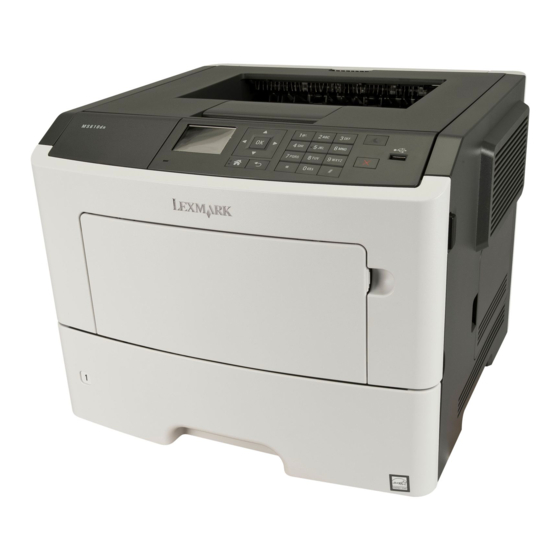
Lexmark MS510 Service Manual
Machine type 4514-630, -635, -646, -638, -639, -649
Hide thumbs
Also See for MS510:
- Service manual (344 pages) ,
- User manual (255 pages) ,
- Manual (20 pages)

Related Manuals for Lexmark MS510


Summary of Contents for Lexmark MS510
-
Page 1: Service Manual
MS510, MS610, M1145, & M3150 Machine Type 4514-630, -635, -646, -638, -639, -649 Service Manual • Start diagnostics • Maintenance • Safety and notices • Trademarks • Index December 04, 2014 www.lexmark.com P/N 12G2826... -
Page 2: December
December 04, 2014 The following paragraph does not apply to any country where such provisions are inconsistent with local law: LEXMARK INTERNATIONAL, INC., PROVIDES THIS PUBLICATION “AS IS” WITHOUT WARRANTY OF ANY KIND, EITHER EXPRESS OR IMPLIED, INCLUDING, BUT NOT LIMITED TO, THE IMPLIED WARRANTIES OF MERCHANTABILITY OR FITNESS FOR A PARTICULAR PURPOSE. - Page 3 4514-6xx Assembly 1: Covers Parts catalog...
- Page 4 4514-6xx Assembly 1: Covers Asm-index Units/mach Units/FRU Description Removal procedure 40X8520 Dust cover (250‑sheet tray) “Dust cover removal” on page 257 40X8521 Dust cover (550‑sheet tray) “Dust cover removal” on page 257 40X8054 Rear door and cover “Rear door and cover removal” on page 257 (MS510dn and M1145) 40X8270...
- Page 5 4514-6xx Asm-index Units/mach Units/FRU Description Removal procedure 40X8057 Control panel cover and buttons “Control panel assembly removals” on page 218 (MS610de and M3150) “UICC removals” on page 222 Note: Does not include the UICC. 40X8068 Bezel “Bezel removals” on page 214 (MS610de and M3150) 40X8060 Control panel cover and buttons...
- Page 6 4514-6xx Assembly 2: Electronics 1 Parts catalog...
- Page 7 4514-6xx Assembly 2: Electronics 1 Asm-index Units/mach Units/FRU Description Removal procedure 40X8080 Laser scanning unit “Laser scanning unit (LSU) removal” on page 265 (MS510dn and M1145) 40X8079 Laser scanning unit “Laser scanning unit (LSU) removal” on page 265 (MS610dn, MS610de, M3150dn, and M3150) 40X8343 Fuser, 100 V...
- Page 8 4514-6xx Assembly 3: Electronics 2 Parts catalog...
- Page 9 4514-6xx Assembly 3: Electronics 2 Asm-index Units/mach Units/FRU Description Removal procedure 40X8048 Front door sensor “Front door sensor removal” on page 235 40X8266 Cartridge smart chip “Toner cartridge smart chip contact contact removal” on page 204 40X8046 Toner density sensor “Toner density sensor removal”...
- Page 10 4514-6xx Assembly 4: Frame Parts catalog...
- Page 11 4514-6xx Assembly 4: Frame Asm-index Units/mach Units/FRU Description Removal procedure 40X8393 Transfer roll “Transfer roll removal” on page 210 40X8298 Redrive assembly “Redrive assembly removal” on page 260 (MS510dn and M1145) 40X8437 Redrive assembly “Redrive assembly removal” on page 260 (MS610dn and M3150dn) 40X8438 Redrive assembly...
- Page 12 4514-6xx Assembly 5: Option trays Parts catalog...
-
Page 13: Dust Cover Removal" On
4514-6xx Assembly 5: Option trays Asm-index Units/opt Units/FRU Description Removal procedure 40X8287 250-sheet tray 40X8286 550-sheet tray 40X9654 550-sheet tray, lockable 40X8520 Dust cover, 250‑sheet tray “Dust cover removal” on page 257 40X8521 Dust cover, 550‑sheet tray “Dust cover removal” on page 257 40X8262 ACM assembly “ACM assembly removal”... - Page 14 4514-6xx Assembly 6: Maintenance kits Asm-index Units/mach Units/FRU Description Removal procedure 40X8439 Maintenance kit, 100 V (MS510dn and M1145) • 100 V fuser (40X8343) • Paper exit guide (40X8298) • ACM pick roll (40X8297) • Transfer roll (40X8393) • Tray separator roll assembly (40X8444) •...
- Page 15 4514-6xx Asm-index Units/mach Units/FRU Description Removal procedure 40X8435 Maintenance kit, 220 V (MS610dn and M3150dn) • 220 V fuser (40X8024) • Paper exit guide (40X8437) • ACM pick roll (40X8297) • Transfer roll (40X8393) • Tray separator roll assembly (40X8444) •...
- Page 16 4514-6xx Assembly 7: Power cords Asm-index Units/mach Units/FRU Description Removal procedure 40X0269 Power cord, 2.5 m (straight)—USA, Canada 40X0289 Power cord, 1.8 m (straight)—USA 40X3141 Power cord, 2.5 m (straight)—Europe and others 40X0288 Power cord, 2.5 m (straight)—Argentina 40X0271 Power cord, 2.5 m (straight)—United Kingdom 40X0275 Power cord, 2.5 m (straight)—Israel 40X1772...
- Page 17 4514-6xx Assembly 8: Miscellaneous Asm-index Units/mach Units/FRU Description Removal procedure 40X8737 RFID card reader 40X8330 MarkNet N8352 802.11 b/g/n Wireless Print Server 40X4819 Adapter, RS232C serial 40X5315 Screw, Ship with ISP (2) 40X5316 Cable, 14 pin JST for ISP 40X5317 Standoff, Tee with thumbscrew 40X4826 Adapter, N8120 GB INA...
- Page 18 Units/mach Units/FRU Description Removal procedure 40X8557 Font card, Simplified Chinese 40X8555 256MB flash card 40X7856 160GB hard disk (MS610de and M3150) 40X1368 USB cable, packaged (2 m) 40X8695 Relocation kit (MS510) 40X8696 Relocation kit (MS610dn) 40x8697 Relocation kit (MS610de) Parts catalog...
-
Page 19: Product Power Consumption
The product is plugged into an electrical outlet, but the power switch is turned off. The power consumption levels listed in the previous table represent time-averaged measurements. Instantaneous power draws may be substantially higher than the average. Values are subject to change. See www.lexmark.com for current values. Electrical specifications Low-voltage models •... -
Page 20: Operating Clearances
4514-6xx Operating clearances Right 30 cm (12 in.) Front 51 cm (20 in.) Left 20 cm (8 in.) Rear 20 cm (8 in.) 30 cm (12 in.) Allow additional clearance around the printer for adding the optional input trays. Acoustics All measurements are made in accordance with ISO 7779 and conform with ISO 9296. -
Page 21: Operating Environment
4514-6xx Status 1 meter average sound pressure Declared sound power level (Bels) Idle (Standby) Inaudible Inaudible Quiet Mode 51 dBA 6.6 Bels Simplex Printing 54 dBA 6.9 Bels Sleep/Hibernate Mode Inaudible Inaudible Measurements apply to 300 dpi, 600 dpi and 1200 dpi printing. Status 1 meter average sound pressure Declared sound power level (Bels) -
Page 22: Available Internal Options
MarkNet N8130 10/100 fiber interface – RS‑232‑C serial interface This internal option is available only in the MS610de printer model. Media handling options • Standard output bin – 150‑sheet bin (MS510) – 250‑sheet bin (MS610) • Standard tray – 250‑sheet tray (MS510) –... -
Page 23: Por Sequence
4514-6xx Appendix C: Theory of operation POR sequence At power on, the engine code goes through a series of tests to verify hardware integrity. If a hardware failure is detected, then it is reported to the printer. If the POR sequence cannot be completed successfully, then the printer may post an error message identifying that service may be needed. -
Page 24: Simplex Printing
4514-6xx Part First input roller Secondary input roller Separator roller Pick rollers Option tray Multipurpose feeder (MPF) The driving force from the main drive motor is transmitted through the MPF gearbox. When the MPF solenoid activates, it allows the MPF sector gear linked to the MPF gearbox to rotate. The MPF pick roll shaft is connected to the MPF sector gear. -
Page 25: Duplex Printing
4514-6xx The media with the embedded toner image goes through the fuser assembly to permanently bond the toner to the media. When it passes between the heat belt and pressure roll of the fuser assembly, the combination of heat and pressure fuses the toner image to the media. -
Page 26: Media Handling Components
4514-6xx Part First input roller Secondary input roller Duplex front deliver roller Duplex rear deliver roller Paper exit roller Media handling components Main drive gearbox The gearbox supplies all mechanical power requirements of the printer. Its motor, through several gears, transfers power to following paths: photoconductor drum, transfer roll, fuser, paper exit, input, duplex, and MPF. -
Page 27: Key Components
Duplex sensor Trailing edge sensor Pass through sensor Index sensor Media present Trailing edge sensor sensor MS510/MS610 sensors Bin full sensor Input sensor Fuser exit MPF paper present sensor sensor Duplex sensor Index sensor Media present Trailing edge sensor... -
Page 28: Other Key Components
4514-6xx Trailing edge sensor Detects the media’s trailing edge as it passes the pick tires. Among other capabilities, this sensor can be used to determine the paper size sensor and the media stack height. MPF sensor Detects the presence of media in the MPF tray. Media present sensor Detects the presence of media in the tray. -
Page 29: Controller Board
MPF pick roller Secondary input roller Duplex rear deliver roller Transfer roll Pick rollers Duplex front deliver roller Separator roll Pick rollers MS510/MS610 rollers Paper exit roller Photoconductor drum Fuser assembly First input roller Fuser exit roller Secondary input roller Duplex rear... - Page 30 4514-6xx Electrophotographic process (EP process) Printhead The printhead scans the photo conductor drum surface with a laser beam. It consists of the following components: • Laser diode (LD) card assembly • Oscillator • Start of scan card assembly When a laser beam is scanned across the photoconductor drum surface from one end to the other while turning on and off the beam, one line of latent image is created.
- Page 31 4514-6xx Step 2: Expose The laser fires a focused beam of light at the surface of the photoconductor and writes an invisible image, called a latent image. The laser beam only discharges the surface where the beam hits the photoconductor. This creates a difference in charge potential between the exposed area and the rest of the photoconductor surface.
- Page 32 4514-6xx This process would be similar to using glue to write on a can and then rolling it over glitter. The glitter sticks to the glue but not to the rest of the can. HVPS Developer Metering Roll Blade Toner DRUM -VDC Drum Surface...
- Page 33 4514-6xx Step 5: Clean The cleaning blade removes any toner that remains on the photoconductor after the transfer process. The toner removed is collected inside the imaging unit. Used Toner Cleaning Blade Charge roll DRUM Appendix C: Theory of operation...
- Page 34 4514-6xx Appendix D: Acronyms Acronyms ASIC Application-Specific Integrated Circuit BLDC Brushless DC Motor Black Only Retract Cyan Charge Coupled Device Carbonless Copy Paper Cyclic Redundancy Check Customer Setup CTLS Capacitance Toner Level Sensing DIMM Dual Inline Memory Module DRAM Dynamic Random Access Memory Enhanced Data Out Electrophotographic Process EPROM...
- Page 35 4514-6xx Microswitch Nonvolatile Memory NVRAM Nonvolatile Random Access Memory Original Equipment Manufacturer Optical Sensor Photoconductor pel, pixel Picture element Power-On Reset POST Power-On Self Test Position Sensing Device Pulse Width Modulation Raster Imaging Processor Read Only Memory SDRAM Synchronous Dual Random Access Memory SIMM Single Inline Memory Module SRAM...
- Page 36 4514-6xx Index accessing 145 Symbols action for prompts 149 [x]‑page jam, clear manual feeder. [25y.xx] 72 automatically display error screens 153 [x]‑page jam, clear standard bin. [20y.xx] 55 clear supply usage history 153 [x]‑page jam, open front door. [20y.xx] 47 clearing custom status 153 [x]‑page jam, open rear door.
- Page 37 4514-6xx quick disk 139 electrophotographic process, theory 316 diagnostics electrostatic‑sensitive parts 157 print tests 133 embedded solutions 163 registration 132 energy diagnostics menu conserving 148 accessing 132 envelopes automatic darkness adjustment 143 tips on using 28 base sensor test 139 environment specifications 305 button test 134 EP process, theory 316...
- Page 38 4514-6xx event log in duplex area 59 print log 144 in front door 47 exterior of the printer in manual feeder 72 cleaning 280 in standard bin 55 in tray 1 62 in tray [x] 66 firmware card 307 labels, paper tips on using 29 hardware tests laser notices 13...
- Page 39 4514-6xx network SE menu print quality troubleshooting accessing 155 blank pages 37 Non‑Lexmark [supply type], see User’s Guide gray background on prints 36 [33.xy] 81 repeating defects 39 Not enough free space in flash memory for resources shadow images appear on prints 39...
- Page 40 ACM assembly, option tray 270 Memory full [38] 80 bail 231 Network [x] software error [54] 80 bezel 214 Non‑Lexmark [supply type], see User’s Guide cartridge gearbox 191 [33.xy] 81 cartridge plunger 211 Not enough free space in flash memory for resources...
- Page 41 4514-6xx main drive gearbox 182 selecting paper 27 media present sensor 247 Serial option [x] error [54] 83 media present sensor flag 249 service checks troubleshooting MPF assembly 227 network service check 122 MPF gearbox 187 service engineer (SE) menu 155 MPF pick tire 230 accessing 155 MPF pick tire cover 230...
- Page 42 4514-6xx troubleshooting, print quality blank pages 37 gray background on prints 36 repeating defects 39 shadow images appear on prints 39 skewed print 40 solid black pages 38 streaked vertical lines appear on prints 42 toner rubs off 42 toner specks appear on prints 43 troubleshooting, service checks network service check 122 unacceptable paper 26...
-
Page 43: Part Number Index
4514-6xx Part number index Part name Page 40X0269 Power cord, 2.5 m (straight)—USA, Canada..................299 40X0270 Power cord, 2.5 m (straight)—Japan......................299 40X0271 Power cord, 2.5 m (straight)—United Kingdom..................299 40X0273 Power cord, 2.5 m (straight)—Traditional Italy..................299 40X0275 Power cord, 2.5 m (straight)—Israel......................299 40X0288 Power cord, 2.5 m (straight)—Argentina....................299 40X0289 Power cord, 1.8 m (straight)—USA......................299 40X0301 Power cord, 2.5 m (straight)—Australia....................299... -
Page 44: X8051
4514-6xx Part name Page 40X8023 Fuser, 110 V............................288 40X8024 Fuser, 220 V............................288 40X8029 Controller board (MS510dn and M1145)....................288 40X8030 Controller board (MS610dn and M3150dn)...................288 40X8043 Duplex sensor and input sensor......................290 40X8044 Index sensor............................290 40X8045 Trailing edge sensor..........................290 40X8046 Toner density sensor..........................290 40X8048 Front door sensor...........................290 40X8050 Narrow media/bin full sensor........................288 40X8051 Nameplate (MS510dn and M1145)......................284... - Page 45 4514-6xx Part name Page 40X8269 Left cover (MS610dn, MS610de, M3150dn, and M3150)..............285 40X8270 Rear door and cover (MS610dn, MS610de, M3150dn, and M3150).............284 40X8271 Top cover (MS610dn, MS610de, M3150dn, and M3150)..............285 40X8272 Nameplate (MS610de and M3150)......................284 40X8273 Rubber foot............................285 40X8275 Duplex assembly............................293 40X8276 Cooling fan (MS510dn, MS610dn, M1145, and M3150dn)..............288 40X8277 Duplex gear assembly..........................293 40X8279 Jam access cover............................293...
- Page 46 40X8605 Prescribe Card (MS510dn, MS610dn, M1145, and M3150dn)..............301 40X8606 Forms and Barcode Card (MS610de and M3150)..................301 40X8607 IPDS card (MS610de and M3150)......................301 40X8608 Prescribe Card (MS610de and M3150)....................301 40X8695 Relocation kit (MS510)...........................302 40X8696 Relocation kit (MS610dn)........................302 40x8697 Relocation kit (MS610de)........................302 40X8737 RFID card reader.............................301...
-
Page 47: X0005
4514-6xx Part name Page 40X8837 Forms and Barcode + Japanese Font (MS510dn, MS610dn, M1145, and M3150dn)......301 40X8850 Redrive shaft............................293 40X9131 MPF assembly (100 sheets)........................284 40X9148 Cartridge plunger...........................284 40X9181 Cooling fan (MS610de and M3150)......................288 40X9651 Right cover (MS610de and M3150)......................284 40X9654 550-sheet tray, lockable.........................296 41X0003 Power supply, 100 V/110 V Latin America.....................290 41X0005 Nameplate (MS610dn and M3150dn)....................284 41X0239 Rear door and cover (MS610de and M3150)..................284... -
Page 48: Part Name Index
4514-6xx Part name index Part name Page 40X8524 1284-B Parallel Interface Card........................301 40X7856 160GB hard disk (MS610de and M3150)....................302 40X7567 1GB DDR3 RAM............................301 40X8305 250-sheet tray............................284 40X8287 250-sheet tray............................296 40X8305 250-sheet tray insert..........................296 40X8555 256MB flash card...........................302 40X7445 2GB DDR3 RAM............................301 40X8086 550-sheet tray............................284 40X8286 550-sheet tray............................296 40X8086 550-sheet tray insert..........................296... -
Page 49: X8272
4514-6xx Part name Page 40X8029 Controller board (MS510dn and M1145)....................288 40X8388 Controller board (MS610de and M3150)....................288 40X8030 Controller board (MS610dn and M3150dn)...................288 40X8276 Cooling fan (MS510dn, MS610dn, M1145, and M3150dn)..............288 40X9181 Cooling fan (MS610de and M3150)......................288 40X8275 Duplex assembly............................293 40X8277 Duplex gear assembly..........................293 40X8043 Duplex sensor and input sensor......................290 40X8520 Dust cover (250‑sheet tray)........................284 40X8521 Dust cover (550‑sheet tray)........................284... - Page 50 4514-6xx Part name Page 40X8279 Jam access cover............................293 40X8080 Laser scanning unit (MS510dn and M1145)...................288 40X8079 Laser scanning unit (MS610dn, MS610de, M3150dn, and M3150)............288 40X8053 Left cover (MS510dn and M1145)......................285 40X8269 Left cover (MS610dn, MS610de, M3150dn, and M3150)..............285 40X8085 Main drive gearbox..........................293 40X8439 Maintenance kit, 100 V (MS510dn and M1145)..................297 40X8441 Maintenance kit, 100 V (MS610de and M3150)..................298 40X8440 Maintenance kit, 100 V (MS610dn and M3150dn)................297...
- Page 51 40X8270 Rear door and cover (MS610dn, MS610de, M3150dn, and M3150).............284 40X8298 Redrive assembly (MS510dn and M1145).....................293 40X8438 Redrive assembly (MS610de and M3150)....................293 40X8437 Redrive assembly (MS610dn and M3150dn)..................293 40X8850 Redrive shaft............................293 40X8695 Relocation kit (MS510)...........................302 40x8697 Relocation kit (MS610de)........................302 40X8696 Relocation kit (MS610dn)........................302 40X8301 Reverse solenoid............................288 40X8737 RFID card reader.............................301...
- Page 52 4514-6xx Part name Page 40X5315 Screw, Ship with ISP (2)..........................301 40X8444 Separator roll assembly..........................296 40X5317 Standoff, Tee with thumbscrew......................301 40X8046 Toner density sensor..........................290 40X8055 Top cover (MS510dn and M1145)......................285 40X8271 Top cover (MS610dn, MS610de, M3150dn, and M3150)..............285 40X8045 Trailing edge sensor..........................290 40X8393 Transfer roll............................293 40X7592 Tray present sensor..........................288 40X1368 USB cable, packaged (2 m) ........................302...
Need help?
Do you have a question about the MS510 and is the answer not in the manual?
Questions and answers