
Related Manuals for Nova Florida Taurus Dual 70


Summary of Contents for Nova Florida Taurus Dual 70
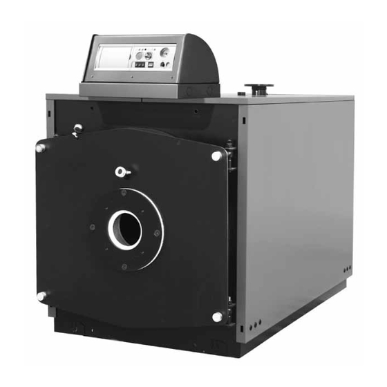
- Page 1 TAURUS DUAL TAURUS DUAL HR PRESSURISED STEEL BOILER INSTALLATION USE AND MAINTENANCE IST 04 C 235 - 03...
-
Page 2: Information
Dear Customer, Thank you selecting our company and choosing to purchase our products. We invite you to carefully read these instructions for correct installation, operation and maintenance of the above-mentioned products. Important In accordance with standard installation regulations, we inform the User that: •... -
Page 3: General Information For Installation And Maintenance Personnel And For The User
General information for installation and maintenance personnel and for the User This instruction manual is an integral and essential part of the product and must be given by the installer to the User who must look after it for future consultation. This manual must accompany the product in the case it is sold or moved. -
Page 4: Table Of Contents
COnTEnTs Information 2 general information for installation and maintenance personnel and for the User..............3 1. User instructions .............................................5 1.1. Control panel ............................................5 1.2. Boiler operation ..........................................7 1.2.1. Switching on ..........................................7 1.2.2. Boiler shutdown ........................................7 1.2.3. Shutdown due to overheating ....................................7 1.3. -
Page 5: User Instructions
UsEr InsTrUCTIOns 1.1. Control panel fig. 1 15 14 13 1. space for programming clock (optional) or for thermoregulation control unit (optional) A thermoregulation control unit (optional) or a programming clock (optional) can be inserted here to programme the times for switching the boiler on and off. - Page 6 Correspondence of indicator lights with boiler status Light 11 Light 3 Light 4 Light 5 Light 8 Switch 11 on „0” or loss of power Switch 11 on „I” GREEN n.a. n.a. n.a. n.a. Burner powered GREEN n.a. n.a. yELLOW request for DHW active GREEN yELLOW...
-
Page 7: Boiler Operation
1.2. Boiler operation Refer to Table 1 for boiler operation status indicators. 1.2.1. switching on NOTE see also Point 3.3 and sub-sections. • Check the value of the water pressure in the system: - Maximum pressure 6 bar – 600kPa; - Minimum pressure 0.8÷1 bar, 80-100 kPa;... -
Page 8: Technical Characteristics And Dimensions
TECHnICAL CHArACTErIsTICs AnD DIMEnsIOns 2.1. Technical characteristics These boilers are steel, pressurised, horizontal cylindrical type, with flame reversing process in the furnace and a third combustion flue pass. They may be used for heating water to a temperature not exceeding boiling point under installation conditions. The boilers meet the essential requirements of the relevant EC Directives, the laws and standards of the countries of destination which are indicated on the technical data plate of the boiler. -
Page 9: Dimensions
2.2. Dimensions 70 – 1300; Hr 70 – 1300 fig. 2 Øb Øc N6 N8 MODEL mm mm mm mm mm mm mm mm mm mm mm mm mm mm mm mm DN/in DN/in DN/in DN/in DN/in 70 - HR 70 1030 54.5 200-250... - Page 10 1400 – 3500; Hr 1400 – 3500 fig. 3 Øb Øc MODEL mm mm mm mm mm mm mm mm mm mm mm mm DN/in DN/in DN/in DN/in DN/in 1400 - HR 1400 1746 1630 1470 1270 2886 2300 831 1300 755 350-400 1”...
-
Page 11: Technical Data
2.3. Technical data Effi- Max. G20 Max. G30 Max. G31 Max. flue Min. Efficiency Min. G20 Min. G30 Min. G31 Min. flue Load loss Heat Heat ciency at Efficiency Min. heat gas con- gas con- gas con- heat at 30% gas con- gas con- gas con-... - Page 12 Effi- Max. G20 Max. G30 Max. G31 Max. flue Min. Efficiency Min. G20 Min. G30 Min. G31 Min. flue Load loss Heat Heat ciency at Efficiency Min. heat gas con- gas con- gas con- heat at 30% gas con- gas con- gas con- on flue output...
-
Page 13: Instructions For The Installer
InsTrUCTIOns FOr THE InsTALLEr 3.1. Installation regulations The boiler is designed in compliance with rules and regulations enforced in the country indicated on the technical data plate. The installation in a different country may be a source of danger for people, animals and property. 3.2. -
Page 14: Hydraulic Connection
3.2.3. Hydraulic connections 3.2.3.1. Thermal hot water system with closed expansion vessel Furnace output ≤ 300.000 kcal/h – pressure 6 bar (fig. 4) The generator must be equipped with: a - Safety valve b - Expansion vessel (connected with a ≥ 18 mm diam. -
Page 15: Air Intake / Flue Gas Systems
3.2.4. Air intake / flue gas system The boilers are built with an open combustion chamber and are designed to be attached to a chimney. The combustion air is taken directly from the environment in which the boiler is installed. The burner needs air for the combustion of solid or liquid fuel. -
Page 16: Electrical Connection
3.3. Electrical connection The electrical connections of a thermal system designed only for the heating of buildings is subject to numerous legal regulations of a general and specific nature for the individual types of applications or fuel. It is therefore necessary to comply with local standards. 3.3.1. -
Page 17: Connection Examples For Riello Burners
3.3.2. Connection examples for riello burners IB R IB R IB R IB R Type of burners listed: 1 - Gas burners RS70, RS100, RS130 2 - Gas burners GAS P/M, GAS 9 P/M, GAS 10 P/ M 3 - Diesel oil burners RL70, RL100, RL130 4 - Diesel oil burners P 140 T/G, T P200/G, P 300 T/G, P 450 T/ G fig. -
Page 18: Door Opening Reversal Procedure
3.4. Door opening reversal procedure Should it be necessary to reverse the door opening direction, proceed as follows: 1. Exchange the external nut (or bush) of a hinge with the diametrically opposite closing bush. Then secure the cone on the hinge side to the door with the internal nut. -
Page 19: Assembly
AssEMBLy 4.1. Boiler housing panels for TAUrUs DUAL and TAUrUs DUAL Hr 70÷400 (fig. 9) a) Wrap the glass wool around the boiler body, ensuring that the bulb-carrying holders (P) located on the right-hand side remain visible. b) Lead the burner-control panel connection cables through the holes present on the lower part of panels (1S) and (1D) according to the opening direction of the door. -
Page 20: Boiler Housing Panels For Taurus Dual And Taurus Dual Hr 500÷1300 (Fig. 10)
4.2. Boiler housing panels for TAUrUs DUAL and TAUrUs DUAL Hr 500÷1300 (fig. 10) a) Wrap the glass wool around the boiler body, ensuring that the bulb-carrying holders located on the right-hand side remain visible. b) Lead the burner/control panel connection cables through the holes present on the lower part of panels (1S) and (1D) according to the opening direction of the door. -
Page 21: Boiler Housing Staves
4.3. Boiler housing staves 1) Wrap the insulation material around the body of the boiler and secure it with the cable ties provided (see pic. 11). DIAGRAM SHOWING THE FIXING OF THE SCHEMA DI CHIUSURA DELLA REGGIA IN INSULATION MATERIAL AROUND THE BOILER PLASTICA PER FISSAGGIO DELLA LANA PLATE WITH THE CABLE TIES SUL FASCIAME DELLA CALDAIA... - Page 22 NOTE: the crossbar shown in the picture, if included, should be positioned between the two square tubes to support the staves. fig. 14 4) Insert the previously prepared staves between the uprights and crossbars as shown in picture 15. fig. 15 5) After all staves are positioned, assemble the casing with self-tapping screws.
- Page 23 6) The control panel supplied with the boiler must be mounted on the support provided in the kit and attached to the front crossbar of the boiler. Pass the cable through the opening shown (see fig. 17). fig. 17 If the kit includes the staves for the panel (completed with mounting holes and openings for all cables) it is advisable to use it for ease of use;...
-
Page 24: Start-Up
sTArT-UP IMPOrTAnT Before start-up, fully insert the flue gas agitators, taking care that they are pushed inside by at least 100 mm. 5.1. Preliminary checks Before starting-up the boiler check that • The plate data corresponds with the electrical power, hydraulic and liquid or gas fuel supply; •... -
Page 25: Operation
OPErATIOn The heating system must be suitably operated so as to ensure optimal combustion with reduced atmospheric emissions of carbon dioxide, unburnt hydrocarbon and soot, as well as to avoid damage to persons or property. Guideline combustion values: FUEL Flue temperature % CO 190°C 0 –... -
Page 26: Maintenance
The temperature gap between flow and return must not exceed 15°C in order to avoid thermal shocks to the boiler structure. The return temperature must not exceed 55°C so as to protect the boiler from corrosion due to condensation of flue gases on surfaces which are too cold. -
Page 27: End-Season Maintenance Or Maintenance Before Long Periods Of Inactivity
A quick clean of the product can be performed by opening the front door only, removing the agitators and brushing the pipes with the brush provided. This operation should be repeated at least once a month during periods of activity of the generator and is intended to avoid combustion residues from blocking the agitators so that these cannot be easily removed. -
Page 28: Declaration Of Conformity
DECLArATIOn OF COnFOrMITy... -
Page 32: Assembly Instructions For The Boiler Control Panel
AssEMBLy InsTrUCTIOns FOr THE BOILEr COnTrOL PAnEL... - Page 33 In case of need, additional side slots (B) are present to host fittings model PG 21 (not provided), that can be used for the passage of electric cables. fig. 21 Openings for Openings for Model cables capillary tubes Taurus Dual 70÷1300 A - B Taurus Dual HR 70÷1300 Taurus Dual 1400÷3500 Taurus Dual HR 1400÷3500...
- Page 34 HOW TO AssEMBLE THE COnTrOL PAnEL • How to remove the satellite cap To remove the satellite cap (A), remove the securing screws (C) first, then fix the control panel (B) onto the boiler as shown below. fig. 22 • How to assemble the control panel plate Fix plate (A) onto the support (B), positioning the special gasket (C) as shown below.
- Page 35 Openings for M5 screws fig. 24 • How to position and secure the support Position the support on the pre-mounted boiler panel as shown in the following diagrams, making sure the holes in the support align with those in the panelling. Secure the support with self-drilling screws, as shown in fig.
- Page 36 Support centring openings for other models fig. 26 Openings for self-drilling screws fig. 27...
- Page 37 • How to mount the complete control panel Remove the right-hand panel of the boiler and make the electrical connections. fig. 28 Mount the satellite cap and the right-hand panel as shown in fig. 29. fig. 29...
- Page 38 • How to mount the complete control panel with the support (TAUrUs DUAL and TAUrUs DUAL Hr 1400÷3500 Fixing the control panel (together with the support and the bracket assembly) must be done in four stages: 1) perform the preliminary operations shown in figs. 22, 23 and 24; arrange for the electrical connections of the control panel;...
- Page 39 Openings for capillary tubes fig. 32 Control panel fixing fig. 33 Control panel fixing fig. 34...
- Page 40 Fondital S.p.A. Via Cerreto, 40 25079 VobArno (brescia) Italy Tel. +39 0365 878.31 - Fax +39 0365 878.304 e mail: info@fondital.it The manufacturer reserves the right to modify the products www.novaflorida.it as it deems necessary and useful, without affecting their basic features.
Need help?
Do you have a question about the Taurus Dual 70 and is the answer not in the manual?
Questions and answers