Table of Contents
Advertisement
Quick Links
Advertisement
Table of Contents

Subscribe to Our Youtube Channel
Related Manuals for Viessmann Vivotronic 050 HK1S


Summary of Contents for Viessmann Vivotronic 050 HK1S
- Page 1 Installation and Service Instructions for the contractor Vitotronic 050, Model HK1S and HK3S Outdoor re-set mixing valve control VITOTRONIC 050 Vitotronic 050, Typ HK1S Vitotronic 050, Typ HK3S Certified as a component part of Viessmann boilers only 5581 529 v1.0 08/2006...
-
Page 2: Safety Precautions
Safety precautions Safety precautions Please ensure that this manual is read and understood before commencing installation. Failure to comply with the issues listed below and details printed in this manual can cause product/property damage, and/or severe personal injury. Ensure all requirements below are understood and fulfilled (including detailed information found in manual subsections). -
Page 3: Table Of Contents
Index Index Heating system designs System versions 1 and 2 ........................................Installation Summary of electrical connections . -
Page 4: Heating System Designs
Heating system designs System version 1 2 M2/M3 20 M2/M3 52 M2/M3 A Vitocontrol-S housing Vitotronic 050 Plug B DHW tank Outdoor temperature sensor C Mixing valve circuit Supply temperature sensor (for model HK1S only one mixing valve circuit can be DHW tank temperature sensor connected) Heating circuit pump... - Page 5 Heating system designs System version 2 System with underfloor heating system The underfloor heating mixing valve circuit must be M1 if the underfloor heating system is regulated with supply and return temperature sensors (optimised control). 2 M2/M3 20 M2/M3 52 M2/M3 A Vitotronic 050 B DHW tank C Mixing valve circuit,...
-
Page 6: Installation
Installation Module Installation 1. Modules pre-installed in Vitocontrol-C panel. 2. For connections see page 10. A1 Power supply module A2 Electronic module A3 Power module A4 Extension module... -
Page 7: Summary Of Electrical Connections
Installation Summary of electrical connections HK1S... - Page 8 Installation Summary of electrical connections (cont.) HK3S...
-
Page 9: The Mounting Bracket And Control Unit Back
Installation The mounting bracket and control unit back 1. Opening on front of Vitocontrol-C is 305 x 129 mm (12 x 5 inches). 2. Frame and socket 3. User interface. 4. Connect the control to electronic module connection “X10”. -
Page 10: Mixing Valve Actuator Connection
Motor for 3-way mixing valve for DHW tank storage system For mixing valve actuator connections see job-specific Vitocontrol C schematic Rated voltage: 120 VAC~ Rated current: max. 0.2 (0.1) Amp Run time: adjustable via coding address ”C3” (factory setting “C3:125” for Viessmann mixing valve actuator) -
Page 11: External Connections - Avd Plug
Installation External connections on plug aVD External contacts A and B are connected to aVD (X6) on module A2 as shown in this diagram and, if applicable, on the job-specific Vitocontrol-C schematic. External heating program changeover/ External ”Mixing valve open” The manually preselected heating program can be modified via this contact (see table below), and the mixing valve can be opened. -
Page 12: Initial Start-Up Controls And Display Elements
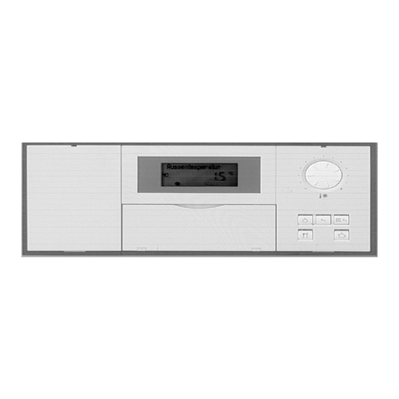
Initial Start-up Controls and display elements First key 1,2 or 3 A Heating circuit selection keys C Rotary selector ”ts” for ”Standard room temperature” B User interface D Open flap ur Space heating time program uw DHW heating time program up DHW re-circulation pump time program Holiday program DHW temperature... -
Page 13: Checking The Heating Circuit Allocation
Initial Start-up Checking the heating circuit allocation Check whether the label for the heating circuit allocation Select the corresponding heating circuit before making has been affixed to the corresponding array of the any adjustments. programming unit. Changing the display language 1. - Page 14 Initial Start-up Integrating the control unit into the LON system (cont.) Single boiler system with Vitotronic 050 and Vitocom 300 downstream Vitotronic 300 Vitotronic 050 Vitotronic 050 Vitocom User no. 1 User no. 10 User no. 11 User no. 99 Code ”77:1”...
-
Page 15: Carrying Out A Participant Check
“00” system design ”4C” Connection sÖ on module A3 ”4E” Connection gS on module A3 ”77” LON participant number ”7F” Detached house or apartment block ”98” Viessmann system number Note Further optional adjustments are listed in code 1 and 2. -
Page 16: Checking Outputs (Actuators) And Sensors
Initial Start-up Checking outputs (actuators) and sensors Relay test 1. Press 9 and simultaneously for approx. 2 seconds. 3. Press . Relay test is completed. Relay test is activated. 2. Control relay outputs with The following relay outputs may be selected: Output 20 ON Notes Output 52 OPEN,... -
Page 17: Adjusting Heating Curves
Initial Start-up Adjusting heating curves Heating curves represent the relationship between the Settings in the factory default setting: outdoor temperature and the supply temperature. To put it Slope ”n” = 1,4 simply: Shift ”N” = 0 The lower the outdoor temperature, the higher the supply temperature. - Page 18 Initial Start-up Adjusting heating curves (cont.) Changing slope and shift (for each heating circuit separately) 1. n for slope, value adjustable from 0.2 to 3.5; for the required value. N for shift, value adjustable from –13 to +40 K / 8.6 to 104 °F.
- Page 19 Initial Start-up Adjusting heating curves (cont.) Adjust the set room temperature (for each heating circuit separately) Standard room temperature: Reduced room temperature: Adjust the set temperature with rotary selector ”ts”. 1. tm for ”Reduced room temperature”. The value will automatically be accepted after approx. 2 seconds.
-
Page 20: Service Scans Service Level Summary
Service scans Service level summary Function Key combination Exit Page Adjusting the display contrast Press the “OK” and –– –– “+” buttons simultaneously; the display will darken Press the “OK” and “-” –– –– buttons simultaneously; the display will get lighter Participant check Press the w and “OK”... -
Page 21: Temperatures And Quick Scans
Service scans Temperatures and quick scans 1. Press 9 and rw simultaneously for approx. 2 seconds. 3. Press . Scanning is completed. 2. Select the required scan with The following values can be scanned, subject to the actual equipment level: Slope M1/M2/M3 Shift M1/M2/M3 Outdoor temp. - Page 22 Service scans Temperatures and quick scans (cont.)
-
Page 23: Scanning Operating Conditions
Service scans Scanning operating conditions 1. Press 3. Press . Scanning is completed. 2. Select the required operating condition scan with The following operating conditions can be scanned subject to the actual equipment level: Participant no. If a LON communication module is installed. Holiday program with departure and return date If a holiday program has been entered. -
Page 24: Troubleshooting
Troubleshooting Faults which are displayed at the programming unit The red fault indicator flashes for all faults. If a fault message is issued, the display flashes ”Fault”. A central fault messaging facility connected to gÖ will be activated. Troubleshooting 1. Press Fault 2. - Page 25 Troubleshooting Faults which are displayed at the programming unit (cont.) Plain text fault display Outdoor temperature sensor Calling up acknowledged fault messages Supply sensor 1. Press for approx. 2 seconds. DHW Tank sensor 1 or 2 The fault will then be displayed. Will only be displayed if a second DHW tank temperature sensor is connected.
- Page 26 Troubleshooting Faults which are displayed at the programming unit (cont.) Fault Cause Remedy System characteristics code DHW tank pump ON: Short circuit Check DHW tank temperature Set DHW temperature = set boiler DHW tank temperature sensor 1 sensor water temperature, priority is (see page 37) cancelled DHW tank pump ”ON”:...
- Page 27 Troubleshooting Faults which are displayed at the programming unit (cont.) Fault Cause Remedy System characteristics code Control mode Open circuit Check solar control unit sensor Only the solar control unit fault Temperature sensor, connects to codes will be displayed Vitosolic S3 Fault Check solar control unit Solar control unit;...
- Page 28 Room temperature sensor, Mixing valve circuit M1 Open circuit dE e Room temperature sensor, Mixing valve circuit M2 Open circuit dE f Room temperature sensor, Mixing valve circuit M3 Communication break Viessmann Check connection Control mode 2-wire BUS...
-
Page 29: Downloading Fault Codes From The Fault Memory (Fault History)
Troubleshooting Faults which are displayed at the programming unit (cont.) LON participants fault messages Preconditions: The control unit must be encoded as fault manager (code ”79:1”). When used in conjunction with the Vitotronic 333, the 333 is programmed as the fault manager. Participant Fault Cause... -
Page 30: Function Description Heating Circuit Control
Function description Heating circuit control unit Brief description The set supply temperature of every heating circuit is The mixing valve motor control changes the actuating and selected by the following parameters: pause times subject to the control difference Outdoor temperature (control deviation). - Page 31 Function description Heating circuit control (cont.) Room temperature Slab Curing Function in conjunction with remote control and room temperature (only in conjunction with mixing valve circuit) feed-back (observe coding address ”b0”). Please note: The slab curing function is selectable on the basis of four Compared to the outdoor temperature, the room different temperature curves.
- Page 32 Function description Heating circuit control (cont.) Underfloor heating Supply temperature control (only mixing valve circuit M1) Differential temperature: An additional return temperature sensor can be connected to The differential temperature can be adjusted via coding achieve an optimum underfloor heating system. The control address ”9F”, unit calculates a set return temperature.
- Page 33 Function description Heating circuit control (cont.) Upper control limit Lower control range limit Electronic maximum limit Electronic minimum limit (only active in operation with Setting range: 10 to 127 °C / 50 to 261°F standard room temperature) Changes via coding address ”C6” Setting range: 1 to 127 °C / 33 to 261°F Changes via coding address ”C5”...
-
Page 34: Dhw Tank Temperature Control
Function description DHW tank temperature control Brief description The DHW tank temperature control operates with a constant Coding addresses which influence the DHW tank temperature. It is the result of starting and stopping the temperature control DHW tank pump. 54, 55, 56, 58 to 62, 64, 66, 67, The switching differential is ±2.5K. - Page 35 Function description DHW tank temperature control (cont.) DHW priority DHW re-circulation pump With DHW priority: The DHW re-circulation pump delivers hot water to the (code ”A2:2”): draw-off points at adjustable times. The set supply temperature will be set to 0 °C / 32 °F Up to four time phases can be set at the time switch.
-
Page 36: Components
Components Components from the parts list Power supply module A1, PN: 7189 737 Front plate, PN: 7818 630 (for HK1S only) Electronic module A2, PN: 7820 788 Front plate, PN: 7818 623 (for HK3S only) Microprocessor with software Only for model HK3S The PCB comprises the relays for controlling the mixing When replacing the PC board: valve motor and the heating circuit pumps. - Page 37 Components Components from the parts list (cont.) DHW tank temperature sensor Connection See job-specific Vitocontrol-C schematic. Check sensor 1. Disconnect one lead of sensor cable 2. Check the sensor resistance at end of both leads. 3. Compare the measurement with the actual temperature displayed (for scanning, see page 21).
- Page 38 Components Components from the parts list (cont.) Strap-on temperature sensor and immersion temperature sensor For recording the supply and return temperature. Connection See job-specific Vitocontrol-C schematic. Check sensor 1. Disconnect one lead of sensor cable. 2. Check the sensor resistance at end of both leads. 3.
- Page 39 Components Components from the parts list (cont.) Outdoor temperature sensor Connection See job-specific Vitocontrol-C schematic. Checking the outdoor temperature sensor 1. Disconnect one lead of sensor cable. 2. Check the sensor resistance at the end of both leads. 3. Where actual values strongly deviate from the curve values, repeat the sensor test and compare with the actual temperature (for scanning, see page 21).
-
Page 40: Mixing Valve Circuit Extension Kit
Components Mixing valve circuit extension kit Mixing valve motor Connection from Vitocontrol-C A Plug in the mixing valve motor Mixing valve open Mixing valve closed Changing the rotational direction Specification Rated voltage: 120 VAC (see page 41). Rated frequency: 60 Hz Remove the cover and reinsert the 3-pole plug A turned by Power consumption: 4 W 180°. -
Page 41: Installation Examples
Components Installation examples Mixing valve insert conversion (if required); see mixing valve installation instructions. Note For system with Modular-Divicon, reverse the rotational direction. Factory default setting Change the mixing valve motor of the mixing valve motor rotational rotational direction for these installation examples direction Heating return... -
Page 42: Temperature Aquastat For Maximum Temperature Limiting
Components Temperature aquastat for maximum temperature limiting Electro-mechanical temperature aquastat according to the liquid expansion principle. Switches the heating circuit pump OFF, when the set value has been exceeded. In such cases, the supply temperature reduces only slowly, i.e it may be several hours before the system restarts again automatically. -
Page 43: Remote Control
Components Remote control Vitotrol 200 (incl. integral room temperature sensor for room temperature hook-up) Settings: Day temperature Heating program Energy saving and party mode Function changes can be made via coding addresses ”A0”, ”b0” to ”b9”, ”C0” to ”C2”, ”C8”, ”E1”, ”E2” and ”F2” (see overview). - Page 44 Components Remote control (cont.) Specification Power supply via KM BUS. Safety class: Protection: IP 30 Permiss. ambient temperature in operation: 0 to +40 ° C / 32 to 104 ° F in storage and in transport: –20 to +65 ° C / 4 to +149 ° F Setting range 1 2 3 4 Standard set...
- Page 45 Components Remote control (cont.) Vitotrol 300 (incl. integral room temperature sensor for room temperature hook-up) Settings: Day and night temperature Holiday program Domestic hot water temperature Switching times Heating program Energy saving and party mode Function changes can be made via coding addresses ”A0”, ”b0” to ”b9”, ”C0” to ”C2”, ”C8”, ”E1” and ”E2” and ”F8” (see overview).
- Page 46 Components Remote control (cont.) Specification Power supply via KM BUS. Safety class: 3 2 1 int. ext. Protection: IP 30 Permiss. ambient temperature in operation: 0 to +40 °C / 32 to 104 °F during storage and transport: –20 to + 65 °C / –4 to +149°F A PCB DIP switches (back of the top casing).
- Page 47 Components Remote control (cont.) Connecting several remote control units When connecting several remote controls to the control unit, install a junction box on site. Version 1 max. max. max. 15 m 15 m 15 m A To control unit On-site connection via junction box: B Junction box (on site) Connect in accordance with the diagram above.
-
Page 48: Room Temperature Sensor
Components Room temperature sensor The room temperature sensor measures the actual room temperature, if the remote control unit cannot be installed in a suitable location. Connection See pages 43 and 45. Check the room temperature sensor 1. Disconnect the wires from the sensor. 2. -
Page 49: Function Extension 0-10 V
Components Extension input module 0 to 10 V To control a supply pump, e.g in a distribution manifold for signalling reduced mode. Electronics T250mA 1 2 3 4 S Ö P 1 2 3 1 2 3 120 VAC – fÖ... -
Page 50: Coding 1
Coding Resetting codes to the factory default setting 1. Press w and rw simultaneously for approx. 2 seconds. 2. Press D. Confirm ”Standard setting? Yes” with With , ”Standard setting? Yes” or ”Standard setting? No” can be selected. Coding 1 Calling up coding 1 1. - Page 51 Coding Coding 1 (cont.) Summary Coding in the factory default setting Possible change System design 00 : 2 Mixing valve circuit M1 00 : 1 Mixing valve circuit M1 with DHW heating without DHW heating Only for model HK3S 00 : 3 Mixing valve circuit M2 without DHW heating 00 : 4...
-
Page 52: Coding Coding 1
Coding Coding 1 (cont.) Coding in the factory default setting Possible change DHW priority M1/M2/M3 A2 : 2 DHW tank priority control for heating circuit pump and mixing valve A2 : 0 Without DHW priority for heating circuit pump A2 : 1 The mixing valve is closed and the heating circuit pump runs whilst the DHW... -
Page 53: Coding 2
Coding Coding 2 The summary from page 54 lists all possible coding addresses. The coding addresses are grouped as follows. Initially the possible coding addresses ”A0” to ”FF” for the mixing valve circuit M1 are scanned, then those for mixing System design valve circuits M2 and M3, again starting with coding Cod. - Page 54 Coding Coding 2 (cont.) Overall summary Coding in the factory default setting Possible change System design (see page 51) General 00 : 2 Mixing valve circuit M1 00 : 1 Mixing valve circuit M1 with DHW heating without DHW heating Only for model HK3S 00 : 3 Mixing valve circuit M2...
- Page 55 Coding Code 2 (cont.) Coding in the factory default setting Possible change DHW (cont.) 58: 0 Without auxiliary function for DHW heating 58 : 1 Input of a second set DHW temperature; adjustable from 1 to 95 °C / 34 to 203 °F (observe coding 58 : 95 address ”56”...
- Page 56 General 76: 0 Without communication module 76: 1 With LON communication module; automatic recognition 76: 2 With Viessmann 2-wire BUS communication module; automatic recognition 77: 10 LON participant number 77: 1 LON participant number, adjustable from 1 to 99 77: 99 Note Allocate each number only once.
- Page 57 Coding Code 2 (cont.) Coding in the factory default setting Possible change General 83: 5 Summer starts: last week of the month 83: 1 Week 1 83: 5 Week 5 84: 7 Summer starts: last day of the week 84: 1 Monday (Sunday) 84: 7...
- Page 58 The outdoor temperature of the sensor connected to the control unit will be used and transmitted via the LON BUS 98: 1 LON communication module Viessmann system number (in conjunction with monitoring several systems) 98 : 2 System number adjustable from 2 to 5...
- Page 59 Coding Code 2 (cont.) Coding in the factory default setting Possible change Mixing valve circuit (cont.) A2: 2 DHW tank priority control for A2: 0 Without DHW tank priority control heating circuit pump and mixing A2: 1 With DHW tank priority applied to mixing valve: valve The mixing valve will be closed while the DHW tank is being heated up;...
- Page 60 Coding Code 2 (cont.) Coding in the factory default setting Possible change Mixing valve circuit (cont.) A5: 5 With heating circuit pump logic function (energy A5: 0 Without heating circuit pump logic function saving mode): With heating circuit pump logic function: Heating circuit pump OFF, if the outdoor Heating circuit pump OFF, if temperature (AT) is 1 K higher than the set room...
- Page 61 Coding Code 2 (cont.) Coding in the factory default setting Possible change Mixing valve circuit (cont.) b0: 0 With remote control: Heating mode/red. mode: b0: 1 Heating mode: weather-compensated weather-compensated Red. mode: with room temperature hook-up b0: 2 Heating mode: with room temperature hook-up Red.
- Page 62 Coding Code 2 (cont.) Coding in the factory default setting Possible change Mixing valve circuit (cont.) b6: 0 With remote control unit and for the heating circuit, operation with room temperature hook-up must be encoded: Without boost heating/rapid setback b6: 1 With boost heating/rapid setback (see page 31) b7: 0...
- Page 63 Coding Code 2 (cont.) Coding in the factory default setting Possible change Mixing valve circuit (cont.) C0: 0 With remote control unit and for the heating circuit, operation with room temperature hook-up must be encoded: Without shut-down time optimisation C0: 1 With shut-down optimisation (max.
- Page 64 Coding Code 2 (cont.) Coding in the factory default setting Possible change Mixing valve circuit (cont.) C9: 0 Control of an underfloor heating system by supply and return temperature sensor: Without heat-up phase C9: 1 With optimisation during the heat-up phase (operates with coding address ”C7”) d5: 0 The heating program changes to ”Constant...
- Page 65 Coding Code 2 (cont.) Coding in the factory default setting Possible change Mixing valve circuit (cont.) F8: –5 For operation in reduced room temperature mode, the set room F8:+10 Temperature limit for temperature will be raised (up to the temperature limit set by coding cancelling reduced mode, address ”F9”) to a value subject to the outdoor temperature, if the F8:–60...
- Page 66 Coding Code 2 (cont.) Example 1 (”F8:–5”, ”F9:–14”) (for °F please see back of manual) Outside temperature in °C A Set standard room temperature 20 °C / 68 °F B Set reduced room temperature 3 °C / 37 °F C Temperature limit –14 °C / 7 °F in accordance with coding address ”F9” D Temperature limit –5 °C / 23 °F in accordance with coding address ”F8”...
-
Page 67: Slab Curing Function Diagrams
Coding Slab curing function diagrams Coding, see page 64. (for F please see back of manual) Temperature time profile 1 (”F1:1”) Days Temperature time profile 2 (”F1:2”) Days Temperature time profile 3 (”F1:3”) Days Temperature time profile 4 (”F1:4”) Days... - Page 68 Coding...
-
Page 69: Parts Lists
Parts lists Parts list model HK1S and HK3S When ordering spare parts 049 Main PCB low voltage Quote the model and serial no. (see model plate) and the 050 Electronics PCB item no. of the required part (as per parts list). 051 Optolink Obtain standard parts from your local supplier. -
Page 70: Parts Lists
Parts lists Parts list model HK1S and HK3S... -
Page 71: Specification
Specification Specification Rated voltage: 120VAC Rated frequency: 60 Hz Primary pump Rated current: 4 A~ DHW tank storage Power system: 4 (2) A consumption: 10 W DHW tank primary Safety class: pump sA: 4 (2) A Protection level: IP 20 DHW circulation pump sK: 4 (2) A... -
Page 72: Keyword Index
Keyword index Keyword index External ”Mixing valve open”, 11, 58 Actual room temperature, display correction, 64 External ”Mixing valve closed”, 11, 58 Actuators, checking, 16 Additional function for DHW heating, 35, 55 Adjusted outdoor temperature, 21, 30, 60 Fault history, 29 Apartment building, 34 Fault manager, 14, 15 Applicability, 74... - Page 73 Users, fault messages, 29 Plug aVD, 11 Participant list, 13 Power supply, 11 Priority control, 30, 35, 52, 59 Pumps, 10 Viessmann 2-wire BUS, 58 Pump idle time, 60 Vitocom 300, 14 Vitotrol 200, 43, 58 Vitotrol 300, 45, 58 Quick scan, 21...
- Page 74 Applicability Applicability Valid for control units Vitotronic 050, model HK1S Part no. 7187 105 Vitotronic 050, model HK3S Part no. 7187 109...
- Page 75 Notes...
- Page 76 +176 +194 +100 +212 +110 +230 Viessmann Manufacturing Company (U.S.) Inc. Viessmann Manufacturing Company Inc. 45 Access Road 750 McMurray Road Warwick, Rhode Island • 02886 • USA Waterloo, Ontario • N2V 2G5 • Canada Tel. (401) 732-0667 • Fax (401) 732-0590 Tel.
Need help?
Do you have a question about the Vivotronic 050 HK1S and is the answer not in the manual?
Questions and answers