Kenwood NX-210 Service Manual
Vhf digital transceiver
Hide thumbs
Also See for NX-210:
- Instruction manual (44 pages) ,
- Specification (2 pages) ,
- Function reference (608 pages)
Table of Contents
Advertisement
Quick Links
VHF DIGITAL TRANSCEIVER
NX-210
Service MANUAL
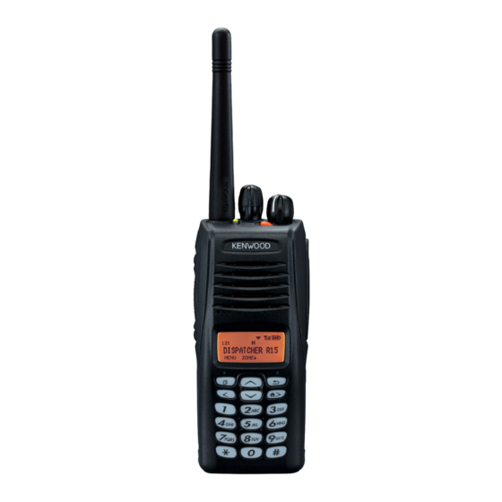
Helical Antenna
(KRA-22: option)
Badge
(B43-1606-04)
Knob (PTT)
(K29-9302-33)
Packing (18 key)
(G53-1823-11)
Does not come with antenna. Antenna is available
as an option.
General ................................................................... 2
System Set-Up ....................................................... 3
Realignment ......................................................... 3
Installation .......................................................... 6
Disassembly For Repair .................................... 8
Circuit Description .......................................... 12
Components Description ............................... 18
Parts List ............................................................. 20
Exploded View .................................................... 31
PACKING .................................................................. 32
Trouble Shooting ............................................ 33
Adjustment ........................................................ 36
Terminal Function ........................................... 58
This product complies with the
RoHS
CONTENTS
directive for the European market.
© 2009-3 PRINTED IN JA PAN
B51-8866-00 ( N ) 443
Knob (Selector)
(K29-9305-03)
Knob (Volume)
(K29-9304-03)
Main cabinet (18 key)
(A02-4076-01)
Display Unit (X54-3660-10) ........................... 66
Tx-Rx Unit (X57-7710-10) ............................... 70
Interconnection Diagram ............................ 74
Schematic Diagram .......................................... 76
Block Diagram .................................................. 88
Level Diagram ................................................... 91
Knb-31A (Ni-Cd Battery Pack) ......................... 92
Knb-32N (Ni-Mh Battery Pack) ........................ 92
Knb-33L (Li-Ion Battery Pack) .......................... 92
Specifications .................................................... 93
This product uses Lead Free solder.
Advertisement
Table of Contents

Related Manuals for Kenwood NX-210


Summary of Contents for Kenwood NX-210
- Page 1 VHF DIGITAL TRANSCEIVER NX-210 SERVICE MANUAL © 2009-3 PRINTED IN JA PAN B51-8866-00 ( N ) 443 Helical Antenna Knob (Selector) (KRA-22: option) (K29-9305-03) Knob (Volume) (K29-9304-03) Badge (B43-1606-04) Knob (PTT) (K29-9302-33) Main cabinet (18 key) (A02-4076-01) Packing (18 key) (G53-1823-11) Does not come with antenna.
-
Page 2: General
fi rmware under the license of Digital Voice Systems, ages resulting from the use of the information contained Inc. herein. Kenwood reserves the right to make changes to any products herein at any time for improvement purposes. GENERAL... -
Page 3: System Set-Up
Frequency range (MHz) RF power Type Choose the type of transceiver TX/RX 136~174 NX-210 K2 A personal computer, programming interface (KPG-36/36A), USB adapter (KCT-53U), and programming software (KPG-111D) Transceiver programming are required for programming. (The frequency, and signaling data are programmed for the transceiver.) - Page 4 NX-210 REALIGNMENT 5-2. Connection procedure 2. How to Enter Each Mode 1. Connect the transceiver to the computer using the inter- Mode Operation face cable and USB adapter (When the interface cable is User mode Power ON KPG-36A, the KCT-53U can be used.).
-
Page 5: Clone Mode
NX-210 REALIGNMENT 6-2. Connection procedure 7. Clone Mode Connect the transceiver to the personal computer using Programming data can be transferred from one trans- the interface cable (KPG-36/36A) and USB adapter (KCT-53U: ceiver to another by connecting them via their external uni- when the interface cable is KPG-36A, the KCT-53U can be versal connectors. -
Page 6: Installation
NX-210 REALIGNMENT Cloning cable this procedure, “CLONE MODE” is displayed if the en- (E30-3325-05) tered password is correct. If the password is incorrect, “CLONE LOCK” is redisplayed. 4. Power ON the target transceiver. 5. Connect the cloning cable (part No. E30-3325-05) to the universal connectors on the source and target. - Page 7 NX-210 INSTALLATION 4. Attach the cushion (G13-1974-04) to the VGS-1 as shown Note: in the fi gure. Be sure not to cover the spring part of the flat spring Note: with the cushion. Be sure to not cover the VGS-1 connector with the cush- ion.
-
Page 8: Disassembly For Repair
NX-210 DISASSEMBLY FOR REPAIR 1. Precautions for Waterproof • The orange packing material on the reverse side of the transceiver is important with respect to the waterproof efficiency of the transceiver. Do not place stickers or other materials on or around the packing material shown in the fi... - Page 9 NX-210 DISASSEMBLY FOR REPAIR ■ Inserting the rubber spacer (J30-1279-04) onto the rear panel 18-key part 1. Bend the two convex parts of the rubber spacer inward q, then fi t the sheet into the space w. Next, bend the one convex part of the rubber spacer in- ward e, and insert the sheet into the rubber spacer.
- Page 10 NX-210 DISASSEMBLY FOR REPAIR ■ Forming the Cord ASSY ■ Correspondence when replacing the case Form the Cord ASSY according to the procedure shown (A02-4076-01) in the fi gure. Apply the dry-surf (410-0019-05) around the LCD and 18- key part of the case when replacing the case.
- Page 11 Part Number Remark Sticker B42-7296-04 “NXDN” is printed. Main Cabinet A02-4076-01 Badge B43-1606-04 “KENWOOD” is printed. Fibrous Sheet (SP) G10-1400-04 Used for fi xing the LCD ASSY on the Illumination Guide (LCD). LCD ASSY B38-0923-05 Adhesive Sheet (LCD) J99-0714-04 Also used for fi xing the Illumination Guide (LCD) on the Control Unit.
-
Page 12: Circuit Description
CIRCUIT DESCRIPTION 1. Overview 2. Frequency Confi guration The NX-210 is a VHF portable transceiver designed to The receiver is a double-conversion superheterodyne operate in the frequency range of 136 to 174MHz. The unit using the first intermediate frequency (IF) of 58.05MHz consists of receiver, transmitter, phase-locked loop (PLL) and the second IF of 450kHz. - Page 13 NX-210 CIRCUIT DESCRIPTION 3-3. Audio Amplifi er Circuit 3-4. Squelch Circuit Audio processing (high-pass filter, low-pass filter, de- It amplifies the demodulated noise signal from IC308 emphasized and so on) at FM mode and decoding at NXDN after filtering through the BPF circuit. Then, the amplified mode are processed by DSP.
- Page 14 NX-210 CIRCUIT DESCRIPTION 4-3. VOX 4-5. APC Circuit IC813 (2/2) amplifi es the audio signal captured in the mi- The APC circuit always monitors the current flowing crophone. The signal is then converted into the DC voltage, through the RF power amplifi er (Q520) and keeps a constant rectifi...
- Page 15 NX-210 CIRCUIT DESCRIPTION 5-3. PLL IC (IC503) 5-4. Doubler (Q513) The PLL IC compares the differences in phases of the The doubler (Q513) extracts the twice harmonic com- VCO oscillation frequency and the VCTCXO reference ponent from the signal from the VCO. This twice harmonic...
- Page 16 NX-210 CIRCUIT DESCRIPTION 6-2. Memory Circuit 6-6. DSP The memory circuit consists of the ASIC (IC308) and the The DSP circuit consists of a DSP (IC302) and processes SRAM (IC303) and fl ash memory (IC301). The fl ash memory the base band signal. The DSP operates on an external clock has capacity of 32M-bit that contains the transceiver control of 18.432MHz (the same as the IC308), the I/O section op-...
- Page 17 NX-210 CIRCUIT DESCRIPTION 8. Signaling Circuit TX-RX unit (X57) F201 8-1. Encode (QT/DQT/LTR/DTMF/2-tone/MSK) RF Final AMP Each signaling data signal of QT, DQT, LTR, DTMF, 2-tone 2.5A IC204 and MSK is generated by the DSP circuit, superposed on /SAVE a modulation signal and output from IC308. The modula-...
-
Page 18: Components Description
NX-210 COMPONENTS DESCRIPTION Display unit (X54-3660-10) Ref. No. Part Name Description IC508 OP AMP (RSSI/VAGC) Ref. No. Part Name Description IC102 LCD contrast IC509,510 DC AMP for BPF IC511 Auto power control IC105 Voltage doubling inverter IC801 D/A converter D1~4... - Page 19 NX-210 COMPONENTS DESCRIPTION Ref. No. Part Name Description Ref. No. Part Name Description Q507 Transistor Ripple fi lter D214 TX/RX LED Q508,509 VCO oscillation D301 Diode Reverse current prevention Q510,511 T/R switch D501,502 Diode Speed up diode Q512~514 Transistor Buffer AMP...
-
Page 20: Parts List
Les articles non mentionnes dans le Parts No. ne sont pas fournis. Y : AAFES (Europe) X : Australia M : Oth er Areas Teile ohne Parts No. werden nicht geliefert. NX-210 (Y50-6480-10) DISPLAY UNIT (X54-3660-10) Desti- Desti- Ref. No. - Page 21 NX-210 PARTS LIST DISPLAY UNIT (X54-3660-10) TX-RX UNIT (X57-7710-10) Desti- Desti- Ref. No. Ad dress Parts No. Description Ref. No. Ad dress Parts No. Description parts nation parts nation S1-18 S70-0509-05 TACT SWITCH C249 CK73HB0J105K CHIP C 1.0UF C250 CK73HB1H471K...
- Page 22 NX-210 PARTS LIST TX-RX UNIT (X57-7710-10) Desti- Desti- Ref. No. Ad dress Parts No. Description Ref. No. Ad dress Parts No. Description parts nation parts nation C381 CK73GB1E105K CHIP C 1.0UF C573 CK73HB1H471K CHIP C 470PF C382-386 CK73HB1A104K CHIP C 0.10UF...
- Page 23 NX-210 PARTS LIST TX-RX UNIT (X57-7710-10) Desti- Desti- Ref. No. Ad dress Parts No. Description Ref. No. Ad dress Parts No. Description parts nation parts nation C646 CK73HB1C103K CHIP C 0.010UF C735 CK73HB1H102K CHIP C 1000PF C647,648 CK73HB1H102K CHIP C...
- Page 24 NX-210 PARTS LIST TX-RX UNIT (X57-7710-10) Desti- Desti- Ref. No. Ad dress Parts No. Description Ref. No. Ad dress Parts No. Description parts nation parts nation C843,844 CK73GB0J475K CHIP C 4.7UF C920 CC73HCH1H101J CHIP C 100PF C845 CK73HB1E103K CHIP C 0.010UF...
- Page 25 NX-210 PARTS LIST TX-RX UNIT (X57-7710-10) Desti- Desti- Ref. No. Ad dress Parts No. Description Ref. No. Ad dress Parts No. Description parts nation parts nation L520 L92-0446-05 BEADS CORE R131 RK73HB1J000J CHIP R 1/16W L521 L41-4778-45 SMALL FIXED INDUCTOR (47NH)
- Page 26 NX-210 PARTS LIST TX-RX UNIT (X57-7710-10) Desti- Desti- Ref. No. Ad dress Parts No. Description Ref. No. Ad dress Parts No. Description parts nation parts nation R315-317 RK73HB1J104J CHIP R 100K 1/16W R507 RK73HB1J124J CHIP R 120K 1/16W R318,319 RK73HB1J000J...
- Page 27 NX-210 PARTS LIST TX-RX UNIT (X57-7710-10) Desti- Desti- Ref. No. Ad dress Parts No. Description Ref. No. Ad dress Parts No. Description parts nation parts nation R591 RK73HB1J223J CHIP R 1/16W R662 RK73HB1J331J CHIP R 1/16W R592,593 RK73HB1J473J CHIP R...
- Page 28 NX-210 PARTS LIST TX-RX UNIT (X57-7710-10) Desti- Desti- Ref. No. Ad dress Parts No. Description Ref. No. Ad dress Parts No. Description parts nation parts nation R815 RK73HB1J103J CHIP R 1/16W R889 RK73HB1J105J CHIP R 1.0M 1/16W R816 RK73HB1J472J CHIP R 4.7K...
- Page 29 NX-210 PARTS LIST TX-RX UNIT (X57-7710-10) Desti- Desti- Ref. No. Ad dress Parts No. Description Ref. No. Ad dress Parts No. Description parts nation parts nation R957 RK73HB1J102J CHIP R 1.0K 1/16W IC208 TC75S51FE (F) MOS-IC R958-961 RK73HB1J101J CHIP R...
- Page 30 NX-210 PARTS LIST TX-RX UNIT (X57-7710-10) Desti- Desti- Ref. No. Ad dress Parts No. Description Ref. No. Ad dress Parts No. Description parts nation parts nation Q214 UMG9N TRANSISTOR Q215 EMD12 TRANSISTOR Q501 2SC5383-T111 TRANSISTOR Q502 2SK879-F (Y) Q503 DTA114YEB...
-
Page 31: Exploded View
NX-210 EXPLODED VIEW Display unit (X54) TX-RX unit (X57 A/2) : N09-2426-14 : N09-6565-05 : N14-0806-04 : N14-0810-04 M2 x 4 : N30-2004-43 G M2.6 x 4 : N30-2604-48 Option board unit M2 x 5 : N83-2005-48 (X57 B/2) K M2 x 6 : N83-2006-43 Parts with the exploded numbers larger than 700 are not supplied. -
Page 32: Packing
NX-210 PACKING Packing fixture Pamphlet 50 Belt clip (J29-0730-05) 14 Instruction manual (B62-2152-00) (B09-0625-03) A Dressed screw (N08-0548-24) H Pan head machine screw (N30-3008-60)x2 46 Item carton case (H52-2316-02) Packing fixture Parts with the exploded numbers larger than 700 are not supplied. -
Page 33: Trouble Shooting
NX-210 TROUBLE SHOOTING Fault Diagnosis of the BGA (Ball Grid Array) IC ■ Overview A fl owchart for determining whether or not the transceiver can be powered on (the LCD does not function even if the power switch is turned on) due to broken BGA parts. - Page 34 NX-210 TROUBLE SHOOTING When a normal ● Checking the output signal value is confirmed. from the ASIC When an abnormal value is confirmed. Points to be checked Normal voltage Remove R218. If the ASIC side is 0V, SBC R218 3.3V the ASIC/FLASH/SRAM may be broken.
- Page 35 Use the KPG-110SM on the NXDN Trunking System side to reprogram the NXDN ESN number. • When a new printed circuit board is used, the Kenwood ESN changes, as does the Transceiver Information dis- play of the KPG-111D, but this does not have any effect on the operation of the transceiver.
-
Page 36: Adjustment
NX-210 TROUBLE SHOOTING NXDN ESN Label (12 digits) (Not used) NXDN ESN Label (12 digits) Kenwood ESN Label Kenwood ESN Label (Not used) Cut-off Line (Not used) Note: A UPC code and UPC barcode is not printed on the Ken- wood ESN Label. - Page 37 NX-210 ADJUSTMENT ■ Key operation • LED indicator Red LED Lights during transmission. “FNC” not appears on the sub LCD display Green LED Lights when there is carrier. Function Display • Sub LCD indicator [Selector] - “FNC” Appears at function on.
- Page 38 NX-210 ADJUSTMENT • Analog mode signaling • LCD display in panel tuning mode CV voltage, AD value, etc None None Sub LCD display None 100Hz Square Wave CNTR Main LCD display LTR Data: LTR Data: AREA=0, GOTO=12 AREA=0, GOTO=12 HOME=12...
- Page 39 NX-210 ADJUSTMENT ■ Adjustment item supplement Adjustment Item Description LCD contrast The contrast of LCD display can be changed. “Counterclockwise Volume” is adjusted at the minimum volume position. Counterclockwise Volume “Clockwise Volume” is adjusted at the maximum volume position. These adjustments can correct the volume variation.
- Page 40 NX-210 ADJUSTMENT ■ Adjustment item and Display Aw (Analog An (Analog Nn (NXDN Nv (NXDN Adjusutment Main LCD Very Narrow) Adjust item Wide) Narrow) Narrow) Order Sub LCD display item display Number Adjustment range 1 point ADJ Common LCD contrast...
- Page 41 NX-210 ADJUSTMENT Aw (Analog An (Analog Nn (NXDN Nv (NXDN Adjusutment Main LCD Very Narrow) Adjust item Wide) Narrow) Narrow) Order Sub LCD display item display Number Adjustment range (RSSI measurement Receive Sensitivity 2 SENS2 value) Section 3 1~256 - *1...
- Page 42 NX-210 ADJUSTMENT [Side2] Analog MAX Deviation Analog MAX Deviation Narrow Wide ADEV ADEV ] press ] hold 5 reference level Adjustments [Side2] QT Deviation QT Deviation Narrow Wide ] press ] hold [Side2] DQT Deviation DQT Deviation Narrow Wide ] press...
- Page 43 In order to turn the volume nut and the channel selector 1 : SSW 2 : SP+ nut, use a recommendation tool. 3 : SP– 4 : MSW KENWOOD part No.: W05-1123-00 5 : EMC 6 : ME ■ Universal connector 7 : PTT 8 : PF...
- Page 44 NX-210 ADJUSTMENT • Panel tuning • PC tuning Connect the wires to the PCB in the connector case of interface cable. For output the wires out of the connector case, need to process the connector case. KPG-36/36A 2 : RED (RX AF OUTPUT)
- Page 45 NX-210 ADJUSTMENT Radio Check Section Condition Measurement Adjustment Specifi cations / Item Test- Remarks Panel test mode PC test mode Unit Terminal Unit Parts Method equipment 1. Frequency 1) CH-Sig: 1-1 1) Test Channel f. counter Panel Check an internal ±0.5ppm...
- Page 46 NX-210 ADJUSTMENT Condition Measurement Adjustment Specifi cations / Item Test- Remarks Panel test mode PC test mode Unit Terminal Unit Parts Method equipment 5. Sensitivity 1) CH-Sig: 1-1 1) Test Channel Check 12dB SINAD or check SSG output Channel: 1...
- Page 47 NX-210 ADJUSTMENT Condition Measurement Adjustment Specifi cations / Item Test- Remarks Panel tuning mode PC test mode Unit Terminal Unit Parts Method equipment 5. Receive 1) Adj item: [RAST] 1) Adj item: Panel [Panel The sub LCD display 2.5V±0.1V Assist Adjust: [✳✳✳✳]...
- Page 48 NX-210 ADJUSTMENT Transmitter Section Condition Measurement Adjustment Specifi cations / Item Test- Remarks Panel tuning mode PC test mode Unit Terminal Unit Parts Method equipment 1. High 1) Adj item: [HIPWR] 1) Adj item: [High Power Panel Panel [Panel 5.0W ±0.2W...
- Page 49 NX-210 ADJUSTMENT Condition Measurement Adjustment Specifi cations / Item Test- Remarks Panel tuning mode PC test mode Unit Terminal Unit Parts Method equipment Maximum 1) Adj item: [Nv NDEV] 1) Adj item: [Maximum Deviation Panel Panel [Panel 1337Hz 1311~1363Hz Deviation Adjust: [✳✳✳✳]...
- Page 50 NX-210 ADJUSTMENT Condition Measurement Adjustment Specifi cations / Item Test- Remarks Panel tuning mode PC test mode Unit Terminal Unit Parts Method equipment 1) Adj item: [Aw QT] 1) Adj item: [QT Devia- Deviation Panel Panel [Panel Write the value as 0.75kHz±0.05kHz...
- Page 51 NX-210 ADJUSTMENT Condition Measurement Adjustment Specifi cations / Item Test- Remarks Panel tuning mode PC test mode Unit Terminal Unit Parts Method equipment 10. Single 1) Adj item: [An TONE] 1) Adj item: [Single Deviation Panel Panel [Panel Write the value as 1.50kHz±0.05kHz...
- Page 52 NX-210 ADJUSTMENT Condition Measurement Adjustment Specifi cations / Item Test- Remarks Panel tuning mode PC test mode Unit Terminal Unit Parts Method equipment 15. BATT 1) Adj item: [BATT] 1) Adj item:[Battery Power Panel Press the PTT detection Adjust: [✳✳✳]...
- Page 53 NX-210 ADJUSTMENT Necessary adjustment and order Mode Signaling Wide Narrow Very Narrow Step1. Balance adjust Step1. Balance adjust Audio Step2. Maximum Deviation (NXDN Narrow) Step2. Maximum Deviation (NXDN Very Narrow) NXDN Step1. Balance adjust CWID Step2. Maximum Deviation (Analog Narrow) Step3.
- Page 54 NX-210 ADJUSTMENT Condition Measurement Adjustment Specifi cations / Item Test- Remarks Panel tuning mode PC test mode Unit Terminal Unit Parts Method equipment 3. Sensitivity 2 1) Adj item: [SENS2] 1) Adj item: Panel Panel [Panel Write the value as adjust Adjust: [✳✳✳]...
- Page 55 NX-210 ADJUSTMENT Condition Measurement Adjustment Specifi cations / Item Test- Remarks Panel tuning mode PC test mode Unit Terminal Unit Parts Method equipment 5. Open 1) Adj item: [An SQL] 1) Adj item: Panel [Panel tuning mode] “Open Squelch” Squelch Adjust: [✳✳✳]...
- Page 56 NX-210 ADJUSTMENT Condition Measurement Adjustment Specifi cations / Item Test- Remarks Panel tuning mode PC test mode Unit Terminal Unit Parts Method equipment Low RSSI 1) Adj item: [Aw LRSSI] 1) Adj item: [Low RSSI Panel [Panel tuning mode] at 118dBm Adjust: [✳✳✳]...
- Page 57 NX-210 ADJUSTMENT Condition Measurement Adjustment Specifi cations / Item Test- Remarks Panel tuning mode PC test mode Unit Terminal Unit Parts Method equipment High RSSI 1) Adj item: [Nv HRSSI] 1) Adj item: [High Panel [Panel tuning mode] Adjust with the ana- at –80dBm...
-
Page 58: Terminal Function
NX-210 TERMINAL FUNCTION Display unit (X54-3660-10) Pin No. Name Function Pin No. Name Function I/O Data bus 6 No connection Chip select output I/O Data bus 7 /RES LCD reset output No connection Address bus 0 output LCDCNT LCD contrast input... - Page 59 NX-210 TERMINAL FUNCTION Pin No. Name Function Pin No. Name Function CN313 (for production) No connection 1~20 I/O Data bus 3 CN336 No connection OPT1 I/O Data bus 4 OPT3 No connection 26P_RD I/O Data bus 5 26P_TD No connection...
- Page 60 NX-210 TERMINAL FUNCTION Option board unit (X57-7710-10 B/2) Pin No. Name Function BTL output – for external speaker Pin No. Name Function CN923 BTL output + for external speaker OPT1 EXT/INT speaker switch input CN805 OPT3 26P_RD BTL output – for internal speaker...
- Page 61 NX-210 TERMINAL FUNCTION Universal connector Rating and Condition Signal Pin No. Name I/O Function Type Parameter Unit EXT/INT speaker switch input Digital L: External speaker ON H: Internal speaker ON [8Ω load] Max output power (1kHz, Batt=7.5V) Analog BTL output + for external speaker [8Ω...
- Page 62 NX-210 TERMINAL FUNCTION CN336 26-pin connector specifi cation Rating and Condition Pin No. Name Signal Type Parameter Unit OPT1 [Input] VIH OPT4 [Input] VIL OPT5 Digital [Output] VOH OPT8 [Output] VOL OPT11 OPT3 [Input] VIH OPT7 [Input] VIL Digital OPT2...
- Page 63 NX-210 TERMINAL FUNCTION Rating and Condition Pin No. Name Signal Type Parameter Unit Output Amplitude (1kHz, 60% deviation) mVp-p Coupling Capacitor µF RXEO Analog Output Impedance 2.2k Ω Allowable Frequency 3000 Input Amplitude (1kHz, 60% deviation) mVp-p Coupling Capacitor µF...
- Page 64 NX-210 TERMINAL FUNCTION Pin No. Name Device Connection Function ANI board 26P_TD VGS-1 Serial data output ANI board PTT signal output OPT4 VGS-1 Enable ANI board OPT10 VGS-1 USEL UART speed select output ANI board Emergency Emergency signal output OPT5...
- Page 65 NX-210 TERMINAL FUNCTION CN923 Option board connector specifi cation Pin No. Name Device Connection Function [COR] Conv/LTR L: Activity receiving H: Not activity receiving [TOR] Conv/LTR L: Activity receiving (Sub Tone or LTR ID is OK) OPT1 ANI board Aux Output...
-
Page 66: Pc Board Display Unit (X54-3660-10)
NX-210 PC BOARD DISPLAY UNIT (X54-3660-10) Component side view (J79-0245-09) Ref. No. Address Ref. No. Address... - Page 67 NX-210 PC BOARD DISPLAY UNIT (X54-3660-10) Component side view (J79-0245-09) J79-0245-09 /RES Component side Layer 1 Layer 2 Layer 3 Layer 4 Foil side...
- Page 68 NX-210 PC BOARD DISPLAY UNIT (X54-3660-10) Foil side view (J79-0245-09) J79-0245-09 TH101 R112 R115 IC102 C119 C122 C133 C138 C137 C125 Ref. No. Address Ref. No. Address IC102 IC105...
- Page 69 NX-210 PC BOARD DISPLAY UNIT (X54-3660-10) Foil side view (J79-0245-09) Component side Layer 1 Layer 2 Layer 3 Layer 4 Foil side...
-
Page 70: Tx-Rx Unit (X57-7710-10)
NX-210 PC BOARD TX-RX UNIT (X57-7710-10) (A/2) Component side view (J79-0246-09 A/2) C731 C693 TX-RX UNIT C933 IC821 (X57-7710-10) D819 CN340 For Boot IC819 R951 C916 CN804 D808 (B/2) R705 IC820 R950 C919 C255 D817 Q209 CN317 OPT10 R954 R952... - Page 71 NX-210 PC BOARD TX-RX UNIT (X57-7710-10) (A/2) Component side view (J79-0246-09 A/2) R255 IC202 R258 C389 IC508 C261 + C630 CN340 C262 R261 L203 For Boot C220 Q212 C348 C269 R341 R374 C350 C267 C270 CN317 Q211 /FLDM R264 X302...
- Page 72 NX-210 PC BOARD TX-RX UNIT (X57-7710-10) (A/2) Foil side view (J79-0246-09 A/2) R808 R569 R408 R409 R410 R380 C373 L310 C510 R812 IC802 R501 R582 C595 R733 R507 R502 C622 R637 C596 C590 C607 IC309 C585 L526 C604 IC502 CN336...
- Page 73 NX-210 PC BOARD TX-RX UNIT (X57-7710-10) (A/2) Foil side view (J79-0246-09 A/2) R615 J79-0246-09 A/2 L532 Q515 C626 R733 D524 TX-RX UNIT R617 C622 R628 (X57-7710-10) R665 R622 R682 C720 R597 XF501 (B/2) C684 L553 C621 Q522 L551 R660 C695...
-
Page 74: Interconnection Diagram
NX-210 INTERCONNECTION DIAGRAM OPTION PC X57-771 B/ LCD ASSY CORD ASSY X42-334 CN337 /LCDRST /LCDRST VLCDLED VLCDLED VLCDLED VLCDLED DISPLAY UNIT X54-366 LCDCNT LCDCNT KEYO1 KEYO1 KEYO0 KEYO0 KEYO3 KEYO3 KEYO2 KEYO2 /KEYI1 /KEYI1 /KEYI0 /KEYI0 /KEYI3 /KEYI3 /KEYI2 /KEYI2... - Page 75 NX-210 INTERCONNECTION DIAGRAM TION PCB 7-771 B/2 SIDE KEY SECTION CN806 DLED DLED Side_G S201 AUXSW UNIVERSAL CONNECTOR TX-RX UNIT X57-771 A/2 CN805 BATT –...
-
Page 76: Schematic Diagram
NX-210 SCHEMATIC DIAGRAM LCD ASSY(B38-0923-05) DISPLAY UNIT(X54-3660-10) D15-18 LCD BACKLIGHT R16 10k R17 10k R18 10k R19 10k R20 10k R21 10k /LCDRST R22 10k R23 10k 0.1u VLCDLED D1-4 D5-10 6KEY BACKLIGHT 12KEY BACKLIGHT LCDCNT D11-14 12KEY CONTROL 1SS388F... - Page 77 NX-210 SCHEMATIC DIAGRAM TX-RX UNIT(X57-7710-10)(A/2) CN337 /LCDRST /LCDRST C301 LCD BACKLIGHT SW Q102 2SA1362-F(GR) R131 VLCDLED C305 BACKLIGHT LCD BACKLIGHT SW Q104 2SC4617(S) R128 /CS4 BUS SW BUS SW IC101 IC104 TC74LCX245FK TC7WZ245FK-F D[0] 12KEY BACKLIGHT SW Q101 D[1] 2SA1832(GR)F...
- Page 78 NX-210 SCHEMATIC DIAGRAM TX-RX UNIT (X57-7710-10) (A/2) L211 L217 /DRST L306 33MDSP A[16] A[17] R324 MCDIAF R318 R319 MCSCKAF C344 CVSS9 FSDET A11 DVDD5 CVDD5 D10 D6 C328 D[6] INT3 INT3 C10 D7 D[7] R327 100k INT2 0.1u D[8] B10 D8...
- Page 79 NX-210 SCHEMATIC DIAGRAM TX-RX UNIT (X57-7710-10) (A/2) R374 R377 2.9mV BUFFER 33AA IC307 X302 SM5023CNDH-G L77-3015-05 R362 18.432MHz C364 0.01u C357 oUTPUT C365 0.01u INHN C366 0.1u C374 0.1u C367 0.1u C375 R369 470k C376 0.1u ASQDET C377 0.1u R370 C378 0.1u...
- Page 80 NX-210 SCHEMATIC DIAGRAM TX-RX UNIT (X57-7710-10) (A/2) VREF CN502 PLD CONTROL L202 R888 R891 33AA 6.8k R901 100k C884 R913 SQL BPF/ SQL DC AMP IC815 TC75W51FK(F) VREF RSTN VIN2 VIN1 D/A CONVERTER VoUT2 VoUT1 IC801 AK2330 VoUT3 VoUT0 VIN3...
- Page 81 NX-210 SCHEMATIC DIAGRAM TX-RX UNIT (X57-7710-10) (A/2) /SCSW VREF VREF C817 1.65V REF/ RX AF SW RX SUMMING AMP 0.1u AF AMP IC805 IC809 C865 RX AF LPF TC7W53FK(F) TC75W51FK(F) IC814 IC802 TC75S51FE(F) R804 1000p TC75S51FE(F) IN+B C866 C846 IN-B...
- Page 82 NX-210 SCHEMATIC DIAGRAM TX-RX UNIT (X57-7710-10) (A/2) R898 C905 VOLTAGE REGULATOR 0.1u VOLTAGE (AF AMP) VOLTAGE REGULATOR Q809 R962 REGULATOR UMG3N (AF AMP) Q806 Q810 SSM6N16FE-F R917 2SB1132(Q,R) R:5.06V R897 INAMT T:0.00V SP CONTROL CN806 D806 R940 R932 EXAMT /KEYI3...
- Page 83 NX-210 SCHEMATIC DIAGRAM TX-RX UNIT (X57-7710-10) (A/2) VOLTAGE REGULATOR (50C) IC204 R:5.00V TK11250CUCB T:4.99V R203 S_DET VoUT R:7.50V T:7.08V CN202 R212 /SAVE CoNT F201 2.5A L204 VOLTAGE REGULATOR REVERSE (33C) CURRENT PREVENTION IC207 R:3.85V R:3.29V TK71733S T:3.84V T:3.29V R220 VoUT...
- Page 84 NX-210 SCHEMATIC DIAGRAM TX-RX UNIT (X57-7710-10) (A/2) R:5.00V R:0mV DC/DC R:15.4V 50T SW T:4.99V T:4.95V T:15.4V CONVERTER Q206 2SA1955A-F L216 REVERSE CURRENT PREVENTION DC/DC CONVERTER 50T CONTROL IC211 IC208 SPEED UP R:3.28V TC75S51FE(F) XC9101D09AKR DIODE T:6.5mV R:7.39V D208 T:7.03V HSC119...
- Page 85 NX-210 SCHEMATIC DIAGRAM TX-RX UNIT (X57-7710-10) (A/2) TEMPERATURE SENSOR IC501 CN501 C514 LM73CIMKX-0 R503 R509 0.01u I2CCK BUFFER AMP SMBCLK Q502 2SK879-F(Y) ALERT R506 I2CSDA SMBDAT ADDR LD/PS2 CPout1 L502 X501 VCCcp2 L77-3014-05 VCCcp1 R511 19.2MHz PLL IC CPout2 LD/PS1...
- Page 86 NX-210 SCHEMATIC DIAGRAM TX-RX UNIT (X57-7710-10) (A/2) /T_R R:3.29V R:4.99V T:1.8mV T:0.00V Q505 EMD9 BUFFER AMP SW R:0mV Q503 T:4.99V DTA114YEB R:5.00V T:5.00V BUFFER AMP SW R:4.66V BUFFER T:4.67V BUFFER AMP SW AMP SW L527 D515 C567 C584 C601 D517...
- Page 87 NX-210 SCHEMATIC DIAGRAM TX-RX UNIT (X57-7710-10) (A/2) TH504 CN505 D529,530 100k ANTENNA SW D529 R:0mV RF FINAL AMP T:1.60V Q520 HVC131 R:39.2mV RD07MVS1BT122 C744 D530 C758 RF DRIVE AMP L556 L557 L558 L562 L563 L565 T:2.36V Q518 68p(G) 82p(G) HVC131 R:33.8mV...
-
Page 88: Block Diagram
NX-210 BLOCK DIAGRAM I2CCK TX-RX unit (X57-7710-10) Q507 2SC5383-T111 I2CSDA Ripple Filter IC501 LM73CIMKX-0 X302 Q510 SSM6L05FU 18.432MHz Q511 2SJ347F SM5023CNDH-G Temp. IC503 IC307 Sensor SKY72300-362 /SCRST,SCSCK,/ TCXO SCREQ,SCBSY,SCMOSI,SCBCK, /SCSS,SCMISO,/SCWKUP,/SCBFS Loop TCXO Filter IC301 IC303 TCXO X501 Q502 IC502 2SC5 19.2MHz... - Page 89 NX-210 BLOCK DIAGRAM TX/RX : 136~174MHz D529,530 Q514 D519,520 Q516 Q518 Q520 D531,532 2SC5636 HSC277*2 2SK3077F RD01MUS1-T113 RD07MVS1BT122 HVC131*4 Pre- BUFF BUFF Drive Final Final Q512 2SC5636 9 2SK508NV(K52) C376B Q526 V325F EMD5 Q519 V278 DC SW DC SW 2SC5383-T111...
- Page 90 NX-210 BLOCK DIAGRAM Display unit (X54-3660-10) D0~D7 /WR,/LCDRST LCDCNT IC102 NJM2130F3-ZB -10V DCDC IC105 LM2682MMX KEYO 0,1,2,3 KEY Matrix /KEYI 0,1,2,3,4 (6key+12key) 12key Back Light VKEY D5,6,7,8 D9,10 LCD Back Light VLCDLED D15,D16 D17,D18 6key Back Light D1,D2 D3,D4 INTMIC...
-
Page 91: Level Diagram
NX-210 LEVEL DIAGRAM... -
Page 92: Knb-32N (Ni-Mh Battery Pack)
NX-210 OPTIONAL ACCESSORIES KNB-31A (Ni-Cd Battery Pack) : 7.2V 1700mAh KNB-33L (Li-ion Battery Pack) : 7.4V 2000mAh ■ External View KNB-32N (Ni-MH Battery Pack) : 7.2V 2500mAh ■ External View ■ KNB-31A Schematic Diagram ■ Schematic Diagram Discharge terminal side Discharge terminal side –... -
Page 93: Specifications
Audio Distortion ..........Less than 3% Modulation ............16K0F3E, 11K0F3E, 8K30F1E, 8K30F1D, 8K30F7W, 4K00F1E, 4K00F1D, 4K00F7W, 4K00F2D Analog measurements made per TIA/EIA 603 and specifi cations shown are typical. KENWOOD reserves the right to change specifi cations without prior notice or obligation. - Page 94 Unit 3712-3724, Level 37, Tower one Metroplaza, 223 Hing Fong Road, Bp 58416 Villepinte, 95944 Roissy Ch De Gaulle Cedex Kwai Fong, N.T., Hong Kong KENWOOD House, Dwight Road, Watford, Herts., 1 Ang Mo Kio Street 63, Singapore 569110 WD18 9EB United Kingdom...
- Page 95 NX-210 NX-210 PC BOARD PC BOARD DISPLAY UNIT (X54-3660-10) DISPLAY UNIT (X54-3660-10) Component side view (J79-0245-09) Component side view (J79-0245-09) J79-0245-09 /RES Component side Ref. No. Address Ref. No. Address Layer 1 Layer 2 Layer 3 Layer 4 Foil side...
- Page 96 NX-210 NX-210 PC BOARD PC BOARD DISPLAY UNIT (X54-3660-10) DISPLAY UNIT (X54-3660-10) Foil side view (J79-0245-09) Foil side view (J79-0245-09) J79-0245-09 TH101 R112 R115 IC102 C119 C122 C133 C138 C137 C125 Component side Ref. No. Address Ref. No. Address Layer 1...
- Page 97 NX-210 NX-210 PC BOARD PC BOARD TX-RX UNIT (X57-7710-10) (A/2) TX-RX UNIT (X57-7710-10) (A/2) Component side view (J79-0246-09 A/2) Component side view (J79-0246-09 A/2) R255 IC202 R258 C389 C731 C693 TX-RX UNIT C933 IC508 C261 + IC821 C630 (X57-7710-10) D819...
- Page 98 NX-210 NX-210 PC BOARD PC BOARD TX-RX UNIT (X57-7710-10) (A/2) TX-RX UNIT (X57-7710-10) (A/2) Foil side view (J79-0246-09 A/2) Foil side view (J79-0246-09 A/2) R808 R569 R408 R409 R410 R380 C373 L310 C510 R615 J79-0246-09 A/2 R812 L532 Q515 IC802...
- Page 99 LCD ASSY(B38-0923-05) TX-RX UNIT(X57-7710-10)(A/2) L211 R374 R377 R898 VOLTAGE C905 CN337 L217 IC307 BUFFER 2.9mV 33AA VOLTAGE REGULATOR (AF AMP) 0.1u VOLTAGE R362 SM5023CNDH-G X302 L77-3015-05 REGULATOR UMG3N Q809 REGULATOR (AF AMP) R962 VOLTAGE /T_R Q505 R:3.29V T:1.8mV R:4.99V T:0.00V TH504 CN505 C357...
- Page 100 TX-RX unit (X57-7710-10) I2CCK Q507 2SC5383-T111 I2CSDA Ripple TX/RX : 136~174MHz Filter IC501 LM73CIMKX-0 X302 Q510 SSM6L05FU D529,530 18.432MHz Q511 2SJ347F SM5023CNDH-G Temp. IC503 Q514 D519,520 Q516 Q518 Q520 D531,532 IC307 Sensor SKY72300-362 2SC5636 HSC277*2 2SK3077F RD01MUS1-T113 RD07MVS1BT122 HVC131*4 /SCRST,SCSCK,/ SCREQ,SCBSY,SCMOSI,SCBCK, TCXO Pre-...
- Page 101 OPTION PCB X57-771 B/2 LCD ASSY SIDE KEY SECTION CORD ASSY CN806 X42-334 CN337 /LCDRST /LCDRST VLCDLED VLCDLED VLCDLED VLCDLED Side_G S201 AUXSW UNIVERSAL DISPLAY UNIT CONNECTOR TX-RX UNIT X54-366 X57-771 A/2 LCDCNT LCDCNT KEYO1 KEYO1 CN805 KEYO0 KEYO0 KEYO3 KEYO3 KEYO2 KEYO2...
Need help?
Do you have a question about the NX-210 and is the answer not in the manual?
Questions and answers