Table of Contents
Advertisement
Instruction Manual
D100422X012
™
Fisher
V250 Ball Valve
Contents
. . . . . . . . . . . . . . . . . . . . . . . . . . . . . . . . .
. . . . . . . . . . . . . . . . . . . . . . . . . . . . .
. . . . . . . . . . . . . . . . . . . . . . . . . . . . . . . . .
. . . . . . . . . . . . . . . . . . . . . . . . . . . . . . . . . .
. . . . . . . . . . . . . . . . . . . . . . . . . . . . . . . . .
. . . . . . . . . . . . . . . . . . . . . . . . . . . . . . . .
. . . . . . . . . . . . . . . . . . . . . . . . . . . .
. . . . . . . . . . . . . . . . . . . . . . . . . . . . . .
. . . . . . . . . . . . . . . . . . . . . . . . . . .
. . . . . . . . . . . . . . . . . . . . . . . . . .
. . . . . . . . . . . . . . . . . . . . . . . . . . . . . . .
. . . . . . . . . . . . . . . . . . . . . . . . . . . . . . . . . . .
Introduction
Scope of Manual
This instruction manual provides installation, maintenance, and parts ordering information for NPS 4 through 24
Fisher V250 valves (figure 1) that mate with ASME flanges. Other instruction manuals provide information covering
the actuator and accessories.
Do not install, operate, or maintain a V250 valve without being fully trained and qualified in valve, actuator, and
accessory installation, operation, and maintenance. To avoid personal injury or property damage, it is important to
carefully read, understand, and follow all the contents of this manual, including all safety cautions and warnings. If you
have any questions about these instructions, contact your
proceeding.
Description
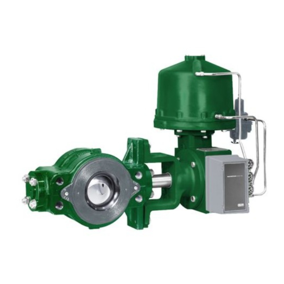
The V250 valve is a flangeless rotary control valve used for high pressure, throttling or on-off control of liquid or gas
applications (see figure 1). These valves operate on a rotary motion input through a splined valve-shaft/actuator-shaft
connection for use with power or manual handwheel actuators. The single seal, dual seal, and flow ring constructions
are covered in this instruction manual.
www.Fisher.com
1
1
1
3
6
. . . . . . . . . . . . . . .
6
. . . . . . . . . . . . . . . . .
7
. . . . . . . . . . . . . . . .
8
8
. . . . . . .
10
. . . . . . . . . . . . . . . . . .
10
. . . . . . . . . . . .
11
. . . . . . . . . .
12
12
15
19
19
19
23
Figure 1. Fisher V250 Ball Valve with 1061 Actuator
W3698
Emerson sales office
or Local Business Partner before
V250 Valve
May 2017
Advertisement
Table of Contents

Related Manuals for Fisher V250


Summary of Contents for Fisher V250
-
Page 1: Table Of Contents
Description The V250 valve is a flangeless rotary control valve used for high pressure, throttling or on‐off control of liquid or gas applications (see figure 1). These valves operate on a rotary motion input through a splined valve‐shaft/actuator‐shaft connection for use with power or manual handwheel actuators. The single seal, dual seal, and flow ring constructions are covered in this instruction manual. - Page 2 Instruction Manual V250 Valve May 2017 D100422X012 Table 1. Specifications Valve Sizes and End Connection Styles Flow Characteristic Modified equal percentage NPS 4 through 24 flangeless valves retained by line flange bolts and designed to fit between ASME raised‐face or ring‐type joint flanges. See table 2 for...
-
Page 3: Installation
5. A V250 valve is normally shipped as part of a control valve assembly, with a power or manual handwheel actuator mounted on the valve. If the valve and actuator have been purchased separately or if the actuator has been... - Page 4 WARNING The V250 is not necessarily grounded to the pipeline when installed. If the process fluid or the atmosphere around the valve is flammable, personal injury or property damage could result from an explosion caused by a discharge of static electricity from the valve components.
- Page 5 Instruction Manual V250 Valve D100422X012 May 2017 Figure 2. Flange Bolt Lengths CL600 BOLTING DIMENSIONS CL900 BOLTING DIMENSIONS VALVE VALVE Raised Face Flanges Ring Type Joint Flanges Raised Face Flanges Ring Type Joint Flanges SIZE, NPS SIZE, NPS ‐‐‐ ‐‐‐...
-
Page 6: Maintenance
A V250 valve with a dual seal construction contains a pipe plug port (key 42, figure 12) on the underside of the valve. This port can be used to relieve internal valve pressure for testing seal integrity when in the pipeline. -
Page 7: Replacing The Drive Shaft Seal
Instruction Manual V250 Valve D100422X012 May 2017 Perform this procedure if there is leakage around the follower shaft (key 7). Such leakage is an indication that the shaft seal, which includes the seal and a backup ring, (key 16) must be replaced. The following procedure may be performed with the valve in the pipeline. -
Page 8: Replacing Ball Seal Or Flow Ring
Instruction Manual V250 Valve May 2017 D100422X012 Note The valve shaft's sealing surfaces are critical in obtaining a good seal. If the valve shafts are scratched, nicked or worn, replace or repair the valve shaft before installing new shaft seals. - Page 9 Instruction Manual V250 Valve D100422X012 May 2017 WARNING The ball (key 2) closes with a shearing motion. To avoid personal injury, keep hands, tools, and other objects away from the ball while stroking the valve. CAUTION Damage to the ball (key 2) may occur if the ball is not in the fully open position while the valve is being removed from the pipeline.
-
Page 10: Installation Of Single Or Dual Ball Seal
Instruction Manual V250 Valve May 2017 D100422X012 Figure 6. Seal & Backup Ring Assembly SEAL BACK‐UP RING CARRIERS SPRING LOADED INTERNAL SEAL RING 28B2099 PRESSURE 5. Proceed to the appropriate Installation procedure to install the removed parts. Installation of Single or Dual Ball Seal 1. -
Page 11: Installing Live-Loaded Ptfe Packing
Instruction Manual V250 Valve D100422X012 May 2017 5. Measure the clearance between the flow ring and the ball with a wire gauge. Add or subtract shim seals until the minimum clearance is 0.38 mm (0.015 inches) for valves used for forward flow and 0.76 mm (0.030 inches) for reverse flow. -
Page 12: Replacing Drive Shaft, Follower Shaft Ball, Bushings, And Valve Outlet Gasket
Instruction Manual V250 Valve May 2017 D100422X012 Replacing Drive Shaft, Follower Shaft, Ball, Bushings, and Valve Outlet Gasket This procedure is to be performed to replace the valve ball, the drive shaft, and the follower shaft, if the ball does not rotate in response to rotation of the actuator end of the drive shaft, or if there is leakage around the outlet gasket. - Page 13 Instruction Manual V250 Valve D100422X012 May 2017 Table 4. Shaft Retainer and Retainer Screw Torques LbfSFt VALVE SIZE, Shaft Retainer Retainer Screw Shaft Retainer Retainer Screw (Key 25) (Key 32) (Key 25) (Key 32) 1390 1025 1760 1295 2390 1760...
- Page 14 Instruction Manual V250 Valve May 2017 D100422X012 Figure 7. Ball Support Post Dimensions VALVE SIZE 41.02 31.62 8.69 23.83 146.1 22.23 30.18 7.95 46.05 40.77 31.37 9.04 63.25 50.67 13.39 41.28 165.1 25.40 46.02 11.13 68.28 62.99 50.42 13.89 75.95 63.37...
-
Page 15: Assembly
Damage to the valve assembly and downstream equipment could occur if the shaft retainer (key 25) should become disengaged from the drive shaft (key 6) during operation of a V250 control valve assembly. To prevent such damage, make sure that the internal threads in the Polygon coupling end of the drive shaft and the external threads of the shaft retainer are cleaned thoroughly before applying thread locking adhesive (high strength) (key 30) as described in step 5 of this assembly procedure. - Page 16 Improper tightening of the retainer screw (key 32) could allow the retainer screw to become disengaged from the follower shaft (key 7) during operation of a V250 control valve assembly. This could cause damage to the valve assembly and downstream equipment. To prevent such damage, make sure that the retainer screw is tightened to the appropriate torque value listed in table 4.
- Page 17 Instruction Manual V250 Valve D100422X012 May 2017 Figure 9. Proper Alignment for Centering the Ball AXIS OF DRIVE SHAFT (KEY 6) AND FOLLOWER SHAFT (KEY 7) FG51287‐A A3142 A - B = 0.127 mm (0.005 INCHES) MAX a. For the follower shaft side of the valve, install several bushing spacer shims around the follower shaft and into the valve.
- Page 18 1. ARROW ON LEVER INDICATES DIRECTION OF ACTUATOR THRUST TO CLOSE VALVE. 48A8905-B 2. PDTC—PUSH DOWN TO CLOSE; PDTO—PUSH DOWN TO OPEN. 48A8827-A 3. THE NPS 16 TO 24 V250 MOUNTING CHART APPLIES TO VALVES USED WITH 1069 ACTUATORS ONLY.
-
Page 19: Actuator Mounting
Use only genuine Fisher replacement parts. Components that are not supplied by Emerson Automation Solutions should not, under any circumstances, be used in any Fisher valve, because they may void your warranty, might adversely affect the performance of the valve, and could cause personal injury and property damage. - Page 20 Instruction Manual V250 Valve May 2017 D100422X012 Figure 11. Fisher V250 Valve Assembly with Single Seal Construction NOTE: 1. KEY NUMBERS 35, 38, 39, AND 44 ARE NOT SHOWN. APPLY AN ADHESIVE GE84944...
- Page 21 Instruction Manual V250 Valve D100422X012 May 2017 Figure 12. Fisher V250 Valve Assembly with Dual Seal Construction NOTE: 1. KEY NUMBERS 35, 38, 39, AND 44 ARE NOT SHOWN. APPLY AN ADHESIVE GE88081...
- Page 22 Instruction Manual V250 Valve May 2017 D100422X012 Figure 13. Live Loaded Packing Assembly NPS 6, 10 ,12, & 16 (4X3‐1/2” SHAFT) NPS 6, 12, 24, NPS 4, 8, 10, NPS 4, 12 & 24 20 CL600, & 20 CL900, &...
-
Page 23: Parts List
Instruction Manual V250 Valve D100422X012 May 2017 Parts List Description 21 Thrust Spacer 22 Spacer 23* O‐Ring (2 req'd) Note 24 Washer Contact your Emerson sales office for part ordering information. 25 Shaft Retainer 26 Adaptor Ring 27 Cap Screw 28... -
Page 24: D100422X012 May
Responsibility for proper selection, use, and maintenance of any product remains solely with the purchaser and end user. Fisher is a mark owned by one of the companies in the Emerson Automation Solutions business unit of Emerson Electric Co. Emerson Automation Solutions, Emerson, and the Emerson logo are trademarks and service marks of Emerson Electric Co.
Need help?
Do you have a question about the V250 and is the answer not in the manual?
Questions and answers