Sony vaio PCV-W500GN1 Service Manual
17 inch
Hide thumbs
Also See for vaio PCV-W500GN1:
- Specifications (129 pages) ,
- Supplementary manual (9 pages) ,
- Service manual (38 pages)
Table of Contents
Advertisement
Quick Links
SERVICE MANUAL
PCV-W Series
American Area
US Model
Canadian Model
Ver. 6-2005E
Revision History
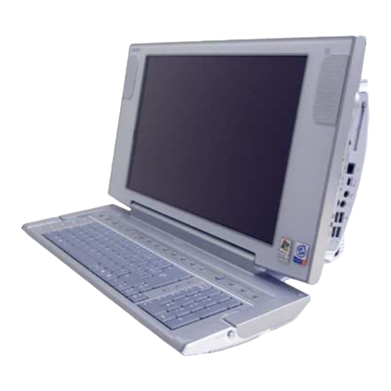
Line up: PCV-W500GN1
PCV-W510G
PCV-W600G
PCV-W700G
• Design and specifications are subject to
change without notice.
2005E0500-1
©2005 Sony Corporation
Published by Sony EMCS NAGANO TEC
9-874-380-15
TOP
FOR SAFETY
DISASSEMBLY
FRAMEHARNESS
( 17inch )
PCV-W700G
PARTS LIST
EXPLODED VIEW
PERSONAL COMPUTER
Advertisement
Table of Contents


Need help?
Do you have a question about the vaio PCV-W500GN1 and is the answer not in the manual?
Questions and answers