Table of Contents
Advertisement
Advertisement
Table of Contents

Related Manuals for Contrec 415


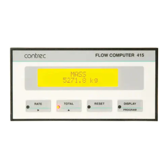
Summary of Contents for Contrec 415
- Page 1 GAS & STEAM FLOW COMPUTER MODEL 415 June 2017 415-M-V3.2...
- Page 2 415-M-V3.2...
-
Page 3: Table Of Contents
3.5.2 Analog Input Linearity Correction 3.6 The Output Pulse 4. Options 4.1 The 4-20mA Output Option 4.1.1 Load Specification 4.1.2 Calculation 4.2 The RS232/422/485 Interface Option 4.2.1 Hardware 4.2.2 Multipoint Communication 4.2.3 Communication Protocol 4.3 Data Logging 4.4 The Relay Output Option 415-M-V3.2... - Page 4 5.2 Definitions 6. Input Circuits 6.1 Frequency Flow Input 6.2 Analog Inputs 6.3 Remote Switches (Model 415A Only) 7. Installation 7.1 General 7.2 Wiring Designations for the Mode 415 7.3 Ex 410 Enclosure Dimensions Appendix Properties of Selected Gases Index 415-M-V3.2...
-
Page 5: List Of Symbols
3600 for units/hour 86400 for units/day kg/m 3 lbs/ft 3 Density at base conditions. ᴘ B kg/m 3 lbs/ft 3 Density at flow conditions. ᴘF Pressure at base conditions. kPa (abs) psia ᴩB Critical pressure of gas. kPa (abs) psia ᴘC 415-M-V3.2... - Page 6 Span (Mass Flowrate at 20mA). kg/day lbs/hr kg/hr lbs/min kg/min lbs/sec kg/sec m 3 /day ft 3 /day Span for a volumetric flowmeter m 3 /hr ft 3 /hr (eg vortex). m 3 /min ft 3 /min m 3 /sec ft 3 /sec 415-M-V3.2...
- Page 7 Temperature at flow conditions. °K °R dm 3 /kg dm 3 /kg Specific Weight of Steam at Reference Conditions. dm 3 /kg dm 3 /kg Specific Weight of Steam at Flow Conditions. Compressibility at base conditions. Compressibility at flow conditions . 415-M-V3.2...
- Page 8 415-M-V3.2...
-
Page 9: Introduction
RTD input, and the 415A with a 4-20mA temperature input. Both accept a 4-20mA pressure input. The Model 415 is designed to supersede the Models 405GS and 405ST. 1 Redlich & Kwong. "An equation of State". Chem Rev, vol 44, p233, 1949. - Page 10 Communities 2014/30/EU, the LVD directive 2014/35/EU and the following standards: EN61326:2013 Electrical equipment for measurement, control and laboratory use – EMC requirements : Residential, Commercial & Light Industry Environment & Industrial Environment. EN61010:2010 Safety requirements for electrical equipment for measurement, control, and laboratory use. 415-M-V3.2...
-
Page 11: Model Number Designation
1.1 MODEL NUMBER DESIGNATION The Model number of an instrument describes which input and output options are installed and the AC mains voltage rating. Model 415 R. 1 0 E C C for Conformal Coating E for 220/240 VAC A for 110/120 VAC... -
Page 12: Specification
Frequency Input Frequency Range: Minimum: 0.25Hz on Rate. 0Hz on Total. Maximum: 10KHz. Input Circuits: Will accept most sine logic and proximity switch inputs (see section 6.1). K-factor Range: 0.1000 to 999,999. Non-Linear Correction: Up to 10 correction points. 415-M-V3.2... - Page 13 4-20mA Output Function: The flowrate selected as the Default display is output on the 4-20mA output. Resolution: 10 bits. Accuracy: Better than 0.1%. Maximum Load: 500 ohms internally powered. 950 ohms from 24 VDC. Isolation: Output is isolated. 415-M-V3.2...
- Page 14 Ideal Gas Corrected Volume (m 3 or ft 3 ). Display: Mass (kg or lbs). Temperature Range: -273°C (-450°F) to 800°C (1472°F). (RTD has a more limited range.) Pressure Range: 0 kPa abs (0 psia) to 100,000 kPa (10,000 psia). 415-M-V3.2...
- Page 15 Uses 1967 IFC Formulation equations to calculate specific weight and enthalpy of steam. Steam Type: Saturated and Superheated. Temperature Range: 20°C (68°F) to 800°C (1472°F). (RTD has a more limited range.) Pressure Range: 1 kPa (abs) (1 psia) to 100,000 kPa (10,000 psia). 415-M-V3.2...
-
Page 16: Operation
Operation 3. OPERATION The Model 415 uses a low power CMOS microprocessor to perform all measurement and control functions. The instrument is fully programmable with all operating parameters and calculation constants user programmable (see Section 5 entitled Calibration for information on programming). - Page 17 The RESET key can be used to reset the totals whenever one of the totals is displayed. Both totals will be reset at the same time. The RESET switch can be disabled during calibration to prevent front panel resetting. 415-M-V3.2...
-
Page 18: Flow Equations For Gases
Operation 3.2 FLOW EQUATIONS FOR GASES This section applies only to gas flow measurement and, if the Model 415 is to be used for steam measurement, the reader can skip this section and go to section 3.3. The Model 415 will accept inputs from a wide range of flowmeters with the flowrate calculated by the equations defined below. - Page 19 Q VB = S V . Z F . .A Q M= .Q VB Differential Pressure Flowmeters With 4-20mA Output And A Square Law Relationship. eg. Orifice Plates, Averaging Pitot Tubes, Target Flowmeters, etc..(7) Q VB = S VB . Q M= 415-M-V3.2...
- Page 20 At lower flowrates, transmitter 2 will be used as a basis of measurement and at higher flowrates, transmitter 1 will be used. The crossover point will occur when the input on transmitter 2 exceeds 20mA. 415-M-V3.2...
- Page 21 0 and 1), the temperature, T F , and pressure, P B . Depending on the gas equation selected, the compressibility factors and density are then calculated. Other parameters must also be programmed and these are fully detailed in section 5. 415-M-V3.2...
- Page 22 If the span is programmed as mass S M = 1000 kg/hr, with the base temperature programmed to 30°C and the base pressure programmed to 220 kPa, then the flow computer will display both mass (kg/hr) and volume (m 3 /hr) corrected to a base condition of 30°C and 220 kPa. 415-M-V3.2...
- Page 23 = 1000 x 15 + 273.2 = 696.1 kg/hr Hence, the span would be programmed as 696.1 kg/hr, the base temperature as 15°C and the base pressure as 101.325 kPa. The corrected volume will now be displayed at standard conditions. 415-M-V3.2...
-
Page 24: Ideal Gas Law
Scaling Factor (K-factor) 9500 Specific Gravity G 1.105 Base Temperature °C Base Pressure 101.325 kPa Timebase of Rate Hours Other parameters can be programmed as required. The instrument will now display the corrected volume and mass flowrates of the gas. 415-M-V3.2... - Page 25 With the instrument set for a linear 4-20mA input signal, the following parameters are programmed: Span (S V ) 1000 Specific Gravity G 1.105 Base Temperature °C Base Pressure 101.325 kPa Timebase of Rate Hours 415-M-V3.2...
-
Page 26: General Gas
It is required to measure Hydrogen via an orifice plate using compressibility. Find the critical temperature and pressure which need to be programmed and the specific weight. From the table, in the appendix, T C = -239.9 C P c = 1296.9 kPa 415-M-V3.2... -
Page 27: Natural Gas
0.554 to 1.000 Carbon Dioxide mol%: 0 to 15% Nitrogen mol%: 0 to 15% Also, the temperature and pressure must be within the following ranges: Temperature -40 to 115°C (-40 to 240°F) Pressure 0 to 34,372 kPa (0 to 5000 psia) 415-M-V3.2... -
Page 28: Steam Measurement
Operation 3.3 STEAM MEASUREMENT The Model 415 incorporates equations to handle both saturated and superheated steam over the following range: Pressure 0 kPa abs (0 psia) to 100,000 kPa abs (10,000 psia) Temperature 100°C (212°F) to 800°C (1472°F). When measuring saturated steam, it is possible to delete either the pressure or temperature sensor since, on the saturation line, there is a corresponding pressure for all temperatures. - Page 29 Energy Flow Equations 13 & 14 are used . Differential Pressure Flowmeters With 4-20mA Output And A Square Law Relationship. eg. Orifice Plates, Averaging Pitot tubes, target flowmeters, etc. Mass Flow ..(17) Energy Flow Equations 13 & 14 are used. 415-M-V3.2...
- Page 30 P. transmitters have square root extractors. Separate spans are then programmed for each transmitter and at lower flowrates transmitter 2 will be used. At higher flowrates, where the output of transmitter 2 exceeds 20mA, transmitter 1 will be used. 415-M-V3.2...
- Page 31 Because the steam is saturated, it is only necessary to use either a temperature or pressure sensor. Because of cost, a temperature probe is used. The main parameters to program are simply: Units US Units K-factor 68.32 Timebase hours 415-M-V3.2...
- Page 32 Hence, steam measurement via a 4-20mA input with square law relationship is selected and the following key parameters are programmed: Units SI Units Span 10,000 Base Temperature 350°C Base Pressure 1300 kPa Timebase hours Steam Superheated 415-M-V3.2...
-
Page 33: Filtering
The value, A, is the filter constant which is programmed during the Calibration routine. The times for the display value to reach 90% and 99% of full swing are given in seconds, for different values of A . 415-M-V3.2... - Page 34 Operation Table 1 - Response to a step Input (in seconds). Note that if A is set to 1 there is no filtering of the input signal. 415-M-V3.2...
-
Page 35: Non-Linearity Correction
F r e q M a x F r e q u e n c y Linear Interpolation is used between points on the curve, except for Factor 1 which maintains a constant value between Frequency 1 and the maximum input frequency. 415-M-V3.2... - Page 36 Hence, the user can program any number of correction points up to a maximum of 10. Note that if all 10 correction points are required, then Frequency 10 will automatically be assigned the value of 0Hz. 415-M-V3.2...
-
Page 37: Analog Input Linearity Correction
At the base temperature and pressure, the flow equation, with non- linearity correction is defined as: Q = Span . A Note: The square root relationship for conventional differential pressure flow devices is handled separately and not by the correction described in this section. 415-M-V3.2... - Page 38 Inches wg at 20mA 52.2007 flowrate flowrate flowrate at 20mA 7075.85 The values of A and A C are input into the table during Calibration and the span would be programmed as 7075.89 such that Q = 7075.89 x A C 415-M-V3.2...
-
Page 39: The Output Pulse
49 counts per second. Note that due to the uneven pulse output spacing on this output, the pulse output cannot be used to drive rate indicators. 415-M-V3.2... - Page 40 Operation Connection of Output Pulse is as follows: Relay or Impulse Counter Model 415 5.6 ohms 3 3 V Zener DC Supply Driving an External Relay or Impulse Counter Model 415 DC Supply Out (8-24V) External Load Resistor 10K Logic Input 5.6 ohms...
-
Page 41: Options
NB. Diagram refers to Version 3 Models Only Version 3 models can be defined by having plug-off green terminals. D C t o D C T erminal Convertor + 1 5 V Digital to Analog Convertor Opto-Isolation - 1 5 V 415-M-V3.2... -
Page 42: Load Specification
20mA or 4mA level respectively. It should be noted that the output will be updated every 0.5 seconds in unison with the display and, between updates, the output value is constant. 415-M-V3.2... - Page 43 L i n k I ( + ) I(-) L O A D 500 ohm m a x i m u m -15 V * For driving impedence loads over 500 ohms, terminate to terminal 21 Two Wire Transmission (Internal Supply) 415-M-V3.2...
- Page 44 Version 3 models can be defined by having plug-off green terminals. T e r m i n a l + 1 5 V I ( + ) I(-) L O A D - 1 5 V External supply of 23 to 30 VDC Three Wire Transmission (External Supply) 415-M-V3.2...
-
Page 45: The Rs232/422/485 Interface Option
( - ) ( + ) RS422 In ( - ) D a t a I n R S 2 3 2 D a t a O u t C T S 20/2B G r o u n d 415-M-V3.2... -
Page 46: Multipoint Communication
Controller and the Instrument. L o a d T wisted Pair 120 ohms L o a d H o s t 120 ohms C o m p u t e r 400 Series 400 Series Instrument Instrument Figure 1 RS422 Interface 415-M-V3.2... - Page 47 120 ohms H o s t C o m p u t e r G n d G n d G n d O u t O u t 400 Series 400 Series Instrument Instrument Figure 2 RS485 Interface 415-M-V3.2...
-
Page 48: Communication Protocol
Options 4.2.3 Communication Protocol The Model 415 has a real time clock and enables the time and date to be set and printed on tickets. The date format can be European (days/months/years) or USA (months/days/hours), while the time is on a 24 hour clock. - Page 49 In half duplex, the commands are not echoed. For more information on the computer interface please consult the manual "The RS232/422/485 Communications Option for the 400 Series, Version 2". 415-M-V3.2...
-
Page 50: Data Logging
Options 4.3 DATA LOGGING The Model 415 can be programmed to output data to a printer, computer or other storage device at the following intervals: 1 minute (Every minute on the minute) 10 minutes (On the hour, at 10 past...etc) -
Page 51: The Relay Output Option
Norm ally Clos ed L o w A l a r m C o m m o n Normally Open Relay 2 Norm ally Clos ed H i g h A l a r m C o m m o n 415-M-V3.2... -
Page 52: Calibration
In stepping through the program sequence, the Parameter Description is always shown. When a value or parameter can be changed, it is always shown as flashing, and the LED's in the switch panels are lit if that key switch can be used to change a value. 415-M-V3.2... - Page 53 To enter a value of, say, 101.325 when the display shows 0.0000, the key would be pressed 9 times until 000.000 is displayed. Once the correct position is reached, the keys can then be used as normal to enter data. 415-M-V3.2...
-
Page 54: Programming Chart
(GENERAL SETUP) DISPLAY CONTRAST ADJUST FLOW UNITS (SI UNITS, US UNITS) TOTAL UNITS (UNITS X 1000 X 1) FLOW TIMEBASE (DAYS, HOURS, MINUTES, SECONDS) FRONT ACCESS (ENABLE, DISABLE) FRONT RESET (ENABLE, DISABLE) RESET TOTALS NOW? (PRESS RESET) SELECT (EXIT) 415-M-V3.2... - Page 55 Only required for differential pressure flowmeters. With volumetric flowmeters, there is no need to enter base temperature & pressure and these values can be left at the default values. Temperatures are entered as °C or °F rather than °K or °R. 415-M-V3.2...
- Page 56 (MASS, VOLUME) (MASS, VOLUME) LOW SPAN (at 20mA) SPAN (at 20mA) SPAN (at 20mA) XXXX XXXX XXXX CUTOFF (Low) FLOW CUTOFF FLOW CUTOFF XX.X% XX.X% XX.X% HIGH SPAN (at 20mA) XXXX For Steam measurement, the Span defaults to mass. 415-M-V3.2...
- Page 57 415A ONLY ±XXX.XX TEMP at 20mA 415A ONLY ±XXX.XX TEMP OFFSET 415R ONLY ±X.XX PRESSURE INPUT (ABSOLUTE, GAUGE) PRESSURE at 4mA ATMOSPHERIC PRESSURE XXXXX XXXXX PRESSURE at 20mA PRESSURE at 4mA XXXXX XXXX PRESSURE at 20mA XXXX SELECT (EXIT) 415-M-V3.2...
- Page 58 XXXXX 4-20mA OUTPUT OPTION IS INSTALLED OUTPUT at 20mA XXXXX DATE FORMAT (dd/mm/yy), mm/dd/yy) DATE XX/XX/XX TIME XX:XX BAUDRATE RS232/RS422/RS485 (300 - 9600) OPTION IS INSTALLED WORD LENGTH (7, 8) PARITY (NONE, ODD, EVEN) SIGNAL TYPE (RS232, RS422, RS485) 415-M-V3.2...
- Page 59 OPTION IS INSTALLED PRINT INTERVAL (1, 10, 30 MINUTES, 1, 6, 12, 24 HOURS) RESET TYPE (FRONT PANEL RESET) (RESET AT 24:00 HOURS) (RESET EACH PRINT) HIGH ALARM SETPOINT XXXXX ALARM OPTION LOW ALARM SETPOINT IS INSTALLED XXXXX SELECT (EXIT) 415-M-V3.2...
- Page 60 INPUTS HIGH FLOW IF ONE OR TWO XX.X mA 4-20mA FLOW INPUTS PRESSURE INPUT XX.X mA TEMPERATURE INPUT IF MODEL 415R, THE ±XXX.XX RTD TEMPERATURE IS DISPLAYED TEMPERATURE INPUT IF MODEL 415A XX.XmA DATE: XX/XX/XX TIME: XX:XX SELECT (EXIT) 415-M-V3.2...
-
Page 61: Definitions
1 and 2. Front Reset If disabled, the front panel reset key becomes inoperable during normal operation. GAS PARAMETERS Default Display The flowrate and total which is normally displayed (eg. Mass or Corrected Volume). 415-M-V3.2... - Page 62 Gilflo meters. Non-Linear applies if a custom non- linearity correction curve is to be programmed. Flow Cutoff The flowrate, as a percentage of the SPAN below which the flow is not displayed or integrated. 415-M-V3.2...
- Page 63 RTD. Pressure Input Both absolute and gauge pressure systems can be used with the Model 415. Atmospheric Pressure If a gauge pressure sensor is used, the atmospheric pressure must be programmed since this will vary with the altitude of the installation.
-
Page 64: Input Circuits
Input Circuits INPUT CIRCUITS The Model 415 has a regulated output which can be used to power sensors. A trimpot on the rear of the instrument allows the voltage to be adjusted in the range of 8-24 Volts and the output can supply a maximum of 50mA. - Page 65 General Specification Switching Threshold: 2.5 Volts (except for input type c, e and f) Maximum Input Voltage: 50V peak Input Impedance Input type a: 100K Input types b & d: Input type c: Input type e: 100K 415-M-V3.2...
- Page 66 I N P U T C O M P A R A T O R 1 0 0 K Pulse Input 1 0 0 R 3 3 K C o m m o n 1 K 2 3 3 K The Frequency Input Circuits 415-M-V3.2...
- Page 67 Input Circuits 1. Squarewave, CMOS or TTL Model 415 Common eg. vortex, pre-amplifiers or magnetic flowmeters 2. Open-Collector Model 415 Common eg. hall effect sensors 3. Reed Switch Model 415 eg. positive displacement flowmeters with reed switch 415-M-V3.2...
- Page 68 Input Circuits 4. Coils Model 415 eg. millivolt signal Use shielded from a turbine flowmeter to case earth cable (single input only) 5. Namur Proximity Switch Model 415 eg. positive displacement flowmeters with 2 wire proximity switch outputs 6. Opto-Sensors...
-
Page 69: Analog Inputs
RTD. M O D E L 4 1 5 R R T D T emperature Sensor I (+) I (-) Signal (+) Signal (-) T wisted Pair C a b l e S h i e l d 415-M-V3.2... - Page 70 When using only one 4-20mA flow input, the signal must be connected to terminal 3 as shown above Shielding: When shielding the input signals, the shield should be connected to the case earth and not connected at the transmitter end (ie. Ground at one end only). 415-M-V3.2...
- Page 71 ( C H 2 ) 2 5 0 o h m Signal Ground The above diagram shows an installation with dual D. P. transmitters to measure flow. When using only one 4-20mA flow input, the signal must be connected to terminal 3 only. 415-M-V3.2...
-
Page 72: Remote Switches (Model 415A Only)
6.3 REMOTE SWITCHES (Model 415A Only) Remote push-buttons can be connected to the Model 415A to duplicate the switches on the front panel. The switches are wired as follows: R E S E T D I S P L A Y 415-M-V3.2... -
Page 73: Installation
Volt power input, the 8-24 Volt output and the pulse output. It is good practice to use shielded cables for all signal connections to the Model 415. Care must be taken to separate signal cables from power cables so as to minimise interference. - Page 74 The basic principle of operation is that the capacitor prevent a series of sparks arcing across the contact as the contact breaks. The series resistor limits the current through the contact when the contact first makes. 415-M-V3.2...
-
Page 75: Wiring Designations For The Mode 415
Installation 7.2 WIRING DESIGNATIONS FOR THE MODEL 415 Terminal Model 415R Model 415A Calibration Link Calibration Link Signal Ground Signal Ground Flow 1 (4-20mA) Flow 1 (4-20mA) PT100 I (+) Temperature (4-20mA) PT100 Signal (+) Reset Switch PT100 Signal (-) - Page 76 Installation Terminal Relay Option High - Normally Open High - Normally Closed High - Common Low - Normally Open Low - Normally Closed Low - Common 415-M-V3.2...
-
Page 77: Ex 410 Enclosure Dimensions
70.0 70.0 71.5 71.5 Gland Holes 130.0 130.0 Gland Holes 3 x ¾“ NPT 3 x M20 Enclosure with 3 x M20 Gland holes Enclosure with 3 x ¾“ NPT Gland holes Material: Cast Aluminium Finish: Light beige powdercoat 415-M-V3.2... -
Page 78: Appendix
8751 1269.2 Methane 0.5539 -82.56 -116.6 4600 667.2 Neon 0.6969 -228.8 -379.8 2756 399.7 Nitrogen 0.9672 -146.9 -232.5 3394 492.3 Nitrous Oxide 1.5199 36.5 97.7 7265 1053.7 Oxygen 1.1048 -118.6 -181.4 5046 731.9 Propane 1.5226 96.67 206.0 4246 615.8 415-M-V3.2... - Page 79 Appendix Propylene 1.4529 91.83 197.3 4620 670.1 Sulphur Dioxide 2.2119 157.7 315.8 7883 1143.4 Xenon 4.5334 16.56 61.8 5836 846.5 415-M-V3.2...
-
Page 80: Index
Pitot Tubes, 17, 27 Default Display, 14, 59 Interference Power Requirements, Density, 16 Suppression, 72 DIL Switch, 62 Isolation, 39, 71 Pressure Input, 11, 61 Dimensions, 10 Printer, 46 Display, 10 Display Contrast, 59 Dual Differential Pressure, 18, 28 415-M-V3.2... - Page 81 Saturated, 26 Setup Parameters, 50 Shielding, 68 Snubbers, 72 Span, 19 Specific Enthalpy, 26 Specific Gravity, 16 Specific Volume, 26 Specification, 10 Standard Conditions, Steam Measurement, Steam Turbines, 27 Supercompressibility Factor, 25 Superheated, 26 Symbols, 5 Target Flowmeters, 17, 27 415-M-V3.2...
Need help?
Do you have a question about the 415 and is the answer not in the manual?
Questions and answers