Table of Contents
Advertisement
Quick Links
Advertisement
Table of Contents

Related Manuals for Contrec 104D


Summary of Contents for Contrec 104D
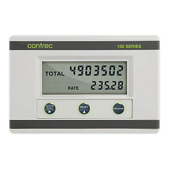
- Page 1 FIELD MOUNTED RATE TOTALISER MODEL 104D March 2015 MAN104DV1.4...
- Page 2 MAN104D-V1.4...
-
Page 3: Table Of Contents
CONTENTS 1. Introduction 2. Specification 3. Operation 3.1 Display 3.2 Test Mode 3.3 Filtering 3.4 Calculation of Rate and Total 3.5 Total Conversion 3.6 Frequency Cutoff 4. Programming 4.1 Program Steps 5. Example 6. Outputs 7. Flowmeter Input 8. Installation 8.1 Wall Mounting 8.2 Removing the Front Panel 8.3 The Main Electronics... - Page 4 MAN104D-V1.4...
-
Page 5: Introduction
The instrument is fully programmable from the front panel; the user can program scaling factors, decimal point positions, filter constants and timebase. The Model 104D Rate Totaliser conforms to the EMC-Directive of the Council of European Communities 2004/108/EC, the LVD directive 2006/95/EC and the... -
Page 6: Specification
2 Specification 2. SPECIFICATION General Display: LCD which is continuously powered. Resettable Total: 7 digits with 10mm (0.4") high digits. Resettable from front panel. Accumulated Total: Displayed when the ACCUM TOTAL button is pressed. Rate: 4½ digits with 8.5mm (0.33") high digits. K-factor: The pulses per unit of measure (eg. - Page 7 Wall Mounting: Universal mounting bracket supplied as standard. Pipe Mounting: A galvanised metal bracket is available which enables the Model 104D to be attached to a 2" vertical or horizontal pipe. Turbine Meter Adaptor: An optional mounting stem is available for mounting the Model 104D directly on turbine flowmeters which have a 1"...
-
Page 8: Operation
4 Operation 3. OPERATION The Model 104D Rate Totaliser accepts a frequency or pulse input from a wide range of flowmeters. The instrument is fully programmable with all operating parameters and calculation constants programmable from the front panel. The setup parameters are stored in a non-volatile memory and are retained for at least 10 years in the event of a power loss. -
Page 9: Test Mode
Operation 5 3.2 TEST MODE The 104D has a Test Mode which can be entered by simultaneously pressing all 3 front panel keys. The tests are as follows: Low Test By pressing the ACCUM TOTAL key, the low alarm output (if installed) will go low. If a 4-20mA option is installed, the output will go to 4mA. -
Page 10: Filtering
6 Operation 3.3 FILTERING Frequency fluctuations caused by pulsating flow through a flowmeter can interfere with the precision of the rate. For this reason, the Model 104D has a digital filter which will average out these fluctuations and enable accurate readings. -
Page 11: Calculation Of Rate And Total
Operation 7 3.4 CALCULATION OF RATE AND TOTAL The flow rate, R, is calculated as follows: f x H where f is the input frequency in Hz (pulses/second). H is the timebase of rate and is 1 for seconds, 60 for minutes, 3600 for hours and 86,400 for days. -
Page 12: Total Conversion
8 Operation 3.5 TOTAL CONVERSION The Total Conversion Factor is programmed to enable the rate to be displayed in one engineering unit and the totals to be displayed in another. For example, the rate can be displayed in gallons/minute and the totals in barrels. The Total Conversion Factor is a division factor which is used to convert the totals to a different unit. -
Page 13: Frequency Cutoff
Note that a low cutoff frequency will result in a correspondingly low response of flow rate update. For example, if the cutoff is set to 0.01Hz the 104D will continue to display the flow rate for 100 seconds even if the signal stops. This is because a cutoff frequency of 0.01Hz means that the time interval between... -
Page 14: Programming
10 Programming 4. PROGRAMMING The Model 104D is fully programmable with all parameters being stored in non- volatile memory. The Program Mode can be entered in one of two ways: 1. By removing the lower cover strip (ie. the dark grey strip along the bottom of the enclosure) and replacing it the wrong side up. -
Page 15: Program Steps
Programming 11 4.1 PROGRAM STEPS Step Comment CAL 0 Pulse Output 0 = No pulse output, low and high alarms. 1 = Scaled pulse output and low alarm. 2 = Unscaled pulse output and low alarm. CAL 1 Scaling Factor - whole numbers. CAL 2 Scaling Factor - digits after the decimal point. - Page 16 12 Programming Step Comment Filter. The filter constant for filtering the input signal. 1 No filtering. 99 Very heavy filtering. CAL 7 Decimal Point for Total Display. The totals can be displayed with 0, 1, 2 or 3 decimal points. CAL 8 Total Conversion Factor - whole numbers.
- Page 17 Programming 13 Step Comment CAL 12 High Alarm or Pulse Output Factor - whole numbers. CAL 13 High Alarm or Pulse Output Factor - digits after the decimal point. CAL 12 & 13 program the flow rate above which the high alarm relay will close.
-
Page 18: Example
14 Example 5. EXAMPLE A flowmeter produces 20.538 pulses per litre and has a maximum output frequency on 200Hz. It is required to display the flow rate in litres/min with 1 decimal point and the total in litres with no decimals. A 4-20mA output is installed and 4mA is to represent 0 litres/m and 20mA is to represent 500 litres/m. -
Page 19: Outputs
Loop Power Supply: 9-28 Volts. Since the 4-20mA output is designed to provide power to the Model 104D, it is not isolated from the input. Hence, all sensors must be self-powering (such as reed switches and coils). If external power is required to power the sensor (eg. - Page 20 16 Outputs Connection to a Sensor requiring External Power Open collector outputs are also provided for high and low flow rate alarms. If a pulse output is programmed, terminals 6 and 5 will act as a pulse out. The output can sink up to 750mA and can be used to power external relays, lights or audible alarms.
- Page 21 Outputs 17 Isolation: Both outputs are separately isolated. Pulse Frequency: 500Hz maximum. Pulse Duration: 1ms if CAL0 = 2 (unscaled pulse output). If CAL0 = 1 (scaled pulse output) the duration of the pulse automatically adjusts to the output frequency: a.
-
Page 22: Flowmeter Input
18 Flowmeter Input 7. FLOWMETER INPUT The Model 104D has an input conditioning circuit which will accept signals from most pulse or frequency producing flowmeters. Links on the LCD panel enable the input circuit to be configured for different signal types. - Page 23 Flowmeter Input 19 +3.3V +3.3V Ipull-up = 0 uA (PULSE link (link 1) not installed) Ipull-up = 15 uA (PULSE link, no external power) Ipull-up = 150 uA (PULSE link, external power) INPUT COMPARATOR 825R LINK 2 1.3V NPS (LINK 3) COIL (LINK 1) 100K 825R...
- Page 24 20 Flowmeter Input 1. Squarewave, CMOS or Pulse Link Settings Switching threshold voltage is 1.3 volts. 2. Open Collector With 15A/150A internal pull up current Link Settings 3. Reed Switch - Battery Powered Link Settings With 15A internal pull up current eg.
- Page 25 Flowmeter Input 21 4. Reed Switch - External DC Power Link Settings With 150A internal pull up current Note: For a switch or reed input with contact bounce link DBH can be switched "on". This will eliminate the effect of switch bounce while limiting the input frequency to 200Hz. 5.
- Page 26 7. Namur Proximity Switch - External DC Power Link Settings 825R input impedance Note: Use this connection for battery or loop powered versions of the Model 104D. If a 4-20mA output is installed, the supply to the proximity switch must be isolated. MAN104D-V1.4...
-
Page 27: Installation
Installation 23 8. INSTALLATION 8.1 WALL MOUNTING A wall mounting bracket is supplied with each instrument. Round head screws should be used to attach the bracket to the wall (countersunk screws should not be used). The bracket is mounted first with the tray section at the bottom. The instrument is then mounted on the bracket with two screws as shown below. -
Page 28: Removing The Front Panel
24 Installation 8.2 REMOVING THE FRONT PANEL The front panel should be removed as follows: 1. Remove the top and bottom cover strips (ie. the dark plastic strip) by levering a screwdriver under one end. 2. Undo the screws retaining the front. Do not remove the screws, they are retained by O-rings. - Page 29 Installation 25 MAN104DV1.4...
-
Page 30: The Main Electronics
26 Installation 8.3 THE MAIN ELECTRONICS The front section of the housing contains the microprocessor and display. It is possible to adjust the display contrast via a small potentiometer on the board. The Display Contrast is shown below and this can be adjusted for optimum contrast. -
Page 31: Wiring
Installation 27 8.4 WIRING When connecting the 104D it is good practice to use shielded cable. The shield should be connected to earth at one end of the cable. The other end of the shield should not be connected. This wiring practice is mandatory in order to comply with the requirements for... -
Page 32: Index
28 Index Index 4-20mA Output, 15 Input Signal, 18 Temperature, 3 Installation, 23 Terminal Accumulated Total, 4 Designations, 26 Alarm Outputs, 16 Test Mode, 5 Timebase, 11 Link Settings, 20 Total Conversion, 8 Low Alarm, 12 Battery Powered, 15 Low Test, 5 Wall Mounting, 23 CAL Sequences, 11 Operating...
Need help?
Do you have a question about the 104D and is the answer not in the manual?
Questions and answers