Table of Contents
Advertisement
Quick Links
Advertisement
Table of Contents

Related Manuals for Contrec 102A


Summary of Contents for Contrec 102A
- Page 1 FIELD MOUNTED RATE TOTALISER MODEL 102A APRIL 2019 MAN102A-V1.3...
- Page 2 MAN102A-V1.3...
-
Page 3: Table Of Contents
CONTENTS 1. Introduction 1.1 Model Number Versions 1.2 Operation 2. Specification 3. Programming 3.1 Program Steps 3.2 Calculation of Rate and Total 3.3 Total Conversion 3.4 Filtering 3.5 Example 4. Signal Input 5. Alarm & Pulse Outputs 6. Installation 6.1 Wall Mounting 6.2 Removing the Front Panel 6.3 The Main Electronics 6.4 Wiring... -
Page 4: Introduction
The instrument is powered from a 4-20mA input signal and therefore, requires no external power. The Model 102A Rate Totaliser conforms to the EMC-Directive of the Council of European Communities 2014/30/EU, the LVD directive 2014/35/EU and the following standards:... -
Page 5: Model Number Versions
5 Introduction 1.1 MODEL NUMBER VERSIONS The Model Number describes the options available for the 102A as follows: Model 102A . X where x denotes the mounting options and will be replaced by one of the following numbers: 2 Wall mount (standard) -
Page 6: Operation
Note that when the input signahil drops below 3.75mA (4-20mA input), a signal error will occur. The display will alternate between the current total and the word "SIGNAL". When the input signal drops below 3.5mA the Model 102A shuts down saving totals in the non-volatile memory. -
Page 7: Specification
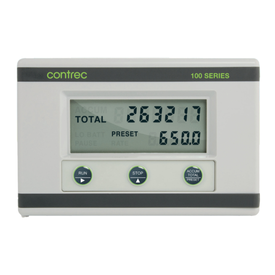
7 Specification 2. SPECIFICATION General Display: LCD, which is continuously powered. Resettable Total: 7 digits with 10mm (0.4") high digits. Resettable from front panel. Accumulated Total: Displayed when the Accumulated Total button is pressed. Rate/Display: 5 digits with 8.5mm (0.33") high digits. Span: The units of measure per timebase (eg. - Page 8 Sealed to Nema 4x or IP67 standards. Cable Entry: By cable glands. Wall Mounting: Universal Mounting Bracket supplied as standard. Pipe Mounting: A galvanised metal bracket is available which enables the Model 102A to be attached to a 2" vertical or horizontal pipe. MAN102A-V1.3...
-
Page 9: Programming
6 Programming 3. PROGRAMMING The Model 102A is fully programmable, with all parameters being stored in non- volatile memory. The Program Mode can be entered in the following way: By removing the lower cover strip (ie. the dark grey strip along the bottom of the enclosure) and replacing it the wrong side up. -
Page 10: Program Steps
Programming 7 3.1 PROGRAM STEPS Step Comment CAL 00 Pulse Output. 0 = No pulse output, low and high alarms 1 = Scaled pulse output and low alarm CAL 01 Span - whole numbers. CAL 02 Span - digits after the decimal point. The Span is the number of units of measure per timebase (eg. - Page 11 8 Programming Step Comment CAL 06 Filter. Fluctuations in the flowrate can be filtered out so that the Rate is held steady. The filter value is programmed between 1 - 99 where "1" represents no filtering and 99 is maximum. See section 3.4.
- Page 12 Programming Step Comment CAL 11 Low Alarm - digits after the decimal point. CAL 10 & 11 program the flowrate below which the low alarm relay will close. The value can be programmed in the range 0 to 999,999. CAL 12 High Alarm or Pulse Output Factor - whole numbers.
-
Page 13: Calculation Of Rate And Total
Programming 3.2 CALCULATION OF RATE AND TOTAL 3.2.1 Analog Input The flowrate, R, is calculated as follows: R = SA if the linear relationship is selected R if a square law relationship is selected where A = the input value S = the span At the minimum input (ie. - Page 14 Programming 3.2.2 The Cutoff Point Because many transducers do not always exactly transmit 4mA when they are at zero rate, it is often necessary to define a rate below which no integration takes place. This is termed the cutoff point and is programmed as a percentage of the Span, S.
-
Page 15: Total Conversion
Programming 3.3 TOTAL CONVERSION The Total Conversion feature enables the rate to be displayed in one engineering unit (eg. gallons/minute) and the totals to be displayed in another engineering unit (eg. barrels). The Span is always programmed in the unit relating to Rate, and the Total Conversion constant is a division factor which can be used to convert the totals to the different unit. -
Page 16: Filtering
Frequency fluctuations caused by pulsating flow through a flowmeter, often makes the Rate impossible to read with any precision. The Model 102A has a digital filter which will average out these fluctuations and enable the Rate to be read to four digit accuracy. The ability to select a suitable filtering level means that highly accurate and stable readings can be obtained without excessive lag. - Page 17 14 Programming Table 1 - Response to a step Input (in seconds). Note that if CAL 06 is set to 01 there is no filtering of the input signal. MAN102A-V1.3...
-
Page 18: Example
Programming 3.5 EXAMPLE A vortex flowmeter has a maximum output of 20.538 litres/min at 20mA. It is required to display the flowrate in litres/min with 1 decimal point and the total in litres with no decimals. High and low alarms are required at 18 l/m and 2 l/m respectively. -
Page 19: Signal Input
Signal Input 4. SIGNAL INPUT The signal input is on terminals 3 and 4 and can be connected as follows: MAN102A-V1.3... -
Page 20: Alarm & Pulse Outputs
Alarm & Pulse Outputs 5. ALARM & PULSE OUTPUTS Open collector outputs are provided for high and low flowrate alarms. The output can sink up to 200mA and can be used to power external relays, lights or audible alarms. The outputs are internally protected against voltage spikes caused by relays and coils. - Page 21 Alarm & Pulse Outputs Connections MAN102A-V1.3...
-
Page 22: Installation
Installation 6. INSTALLATION 6.1 WALL MOUNTING A wall mounting bracket is supplied with each instrument. The bracket should be attached to the wall using round head screws (do not use counter sunk screws). The bracket is mounted with the "tray" section at the bottom. The instrument is then attached to the bracket at the bottom with two screws (see diagram below). -
Page 23: Removing The Front Panel
Installation 6.2 REMOVING THE FRONT PANEL The front of the instrument is removed as follows: 1. Remove both the top and bottom cover strips (ie. the dark plastic strips on the front) by levering a screwdriver under one end. 2. Undo the seven screws retaining the front. Note that the screws should not be removed from the front panel as they are retained by O-rings. - Page 24 21 Installation MAN102A-V1.3...
-
Page 25: The Main Electronics
22 Installation 6.3 THE MAIN ELECTRONICS The front section of the housing contains the microprocessor and display. It is also possible to adjust the display contrast via a small potentiometer on the board. The DISPLAY CONTRAST control is shown below and this can be adjusted for optimum contrast. -
Page 26: Wiring
23 Installation 6.4 WIRING When connecting the Model 102A, it is goods practice to use shielded cable. This wiring practice is mandatory in order to comply with the requirements for Electromagnetic Compatibility as per EMC-Directive 2014/30/EU of the Council of the European Community. -
Page 27: Disposal
23 Installation 7. DISPOSAL 7.1 INSTRUMENT DISPOSAL Contrec instrumentation should not be thrown into the general waste system, this is highlighted by the wheelie bin logo. If within EU member states, this instrument should be disposed of according to the guidelines set by the WEEE (Waste Electrical and Electronic Equipment) directive 2012/19/EU. -
Page 28: Index
Index Index Accumulated Total, 3 Programming, 6 Pulsating Signal, 13 CAL Sequences, 6 Pulse Output, 7, 17 Cutoff Point, 7, 11 Rate, 3, 10 Decimal Point, 6 Removing the Front Display, 4 Panel, 20 Display Test, 3 Resettable Total, 3 Disposal, 24 Response, 13 Filtering, 13...
Need help?
Do you have a question about the 102A and is the answer not in the manual?
Questions and answers