Table of Contents
Advertisement
Advertisement
Table of Contents

Related Manuals for Ruby Tech ES-2410C


Summary of Contents for Ruby Tech ES-2410C
- Page 2 ES-2410C User's Manual 8-Port L2 Plus Managed Fast Ethernet Switch + 2 TP/SFP Gigabit Dual Media Release 1.15 © 2009, RubyTech Corporation. All rights reserved. All brand and product names are trademarks or registered trademarks of their respective companies. Publication date: Jan., 2009...
- Page 3 The information in this document is subject to change without notice. Unless the explicit written permission of RubyTech Corporation, this document in whole or in part shall not be replicated or modified or amended or transmitted, in any from, or by any means manual, electric, electronic, electromagnetic, mechanical, optical or otherwise for any purpose.
- Page 4 DISCLAIMER. EXCEPT AS PROVIDED ABOVE, THE SOFTWARE IS PROVIDED “AS IS ” AND RUBYTECH AND ITS LICENSORS MAKE NO WARRANTIES, EXPRESS OR IMPLIED, WITH REPSECT TO THE SOFTWARE AND DOCUMENTAITON. RUBYTECH AND ITS LICENSORS DISCLAIM ALL OTHER WARRANTIES, INCLUSIVE OF WITHOUT LIMITATION, IMPLIED WARRANTIES OR MERCHANTABILITY, FITNESS FOR A PARTICULAR PURPOSE AND NONINFRINGEMENT.
-
Page 5: Table Of Contents
2-1-3-3. Switch Cascading in Topology ................14 2-1-4. Configuring the Management Agent of ES-2410C ........... 16 2-1-4-1. Configuring the Management Agent of ES-2410C through the Serial RS-232 Port 16 2-1-4-2. Configuring the Management Agent of ES-2410C through the Ethernet Port..18 2-1-5. - Page 6 3-8-1. VLAN Mode ...................... 72 3-8-2. Tag-based Group ....................75 3-8-3. PVID......................... 77 3-8-4. Port-based Group ..................... 79 3-8-5. Management VLAN................... 81 3-9. MAC T ......................82 ABLE 3-10. GVRP C ................... 89 ONFIGURATION 3-11. STP C ....................94 ONFIGURATION 3-11-1.
- Page 7 Revision History Release Date Revision 1.15 01/19/2009 Publication date: Jan., 2009 Revision A1...
-
Page 8: Caution
Caution Circuit devices are sensitive to static electricity, which can damage their delicate electronics. Dry weather conditions or walking across a carpeted floor may cause you to acquire a static electrical charge. To protect your device, always: • Touch the metal chassis of your computer to ground the static electrical charge before you pick up the circuit device. -
Page 9: About This User's Manual
About this user’s manual In this user’s manual, it will not only tell you how to install and connect your network system but configure and monitor the ES-2410C through the built-in CLI and web by RS-232 serial interface and Ethernet ports step-by-step. Many... -
Page 10: Introduction
1. Introduction 1-1. Overview of ES-2410C ES-2410C, 8 Fast Ethernet + 2 Gigabit L2 Plus Managed Switch, implemented 8 10/100Mbps TP + 2 Gigabit dual media ports with TP/SFP(or GBIC), is a standard switch that meets all IEEE 802.3/u/x/z Gigabit, Fast Ethernet and Ethernet specifications. - Page 11 DHCP Option 82: This feature enables the Dynamic Host Configuration Protocol (DHCP) relay agent information (option 82) (ES-2410C switch) to include information about itself and the attached client when forwarding DHCP requests from a DHCP client to a DHCP server via Trust Port. The DHCP server can use this information to assign IP addresses、gateway、subnet...
-
Page 12: Checklist
Hardware • Supports 8-port 10/100M TP ports with Nway and auto MDIX function • In ES-2410C, it supports 2 Gigabit dual media ports(TP/SFP) and 2 slots for removable SFP module supporting 1000M SFP fiber module • In ES-2410C, it supports 2 Gigabit dual media ports(TP/GBIC) and 2 slots for removable GBIC module supporting 1000M GBIC fiber module •... - Page 13 • Supports to send the trap event while monitored events happened • Supports default configuration which can be restored to overwrite the current configuration which is working on via web browser and CLI • Supports on-line plug/unplug SFP/GBIC modules • Supports 5 kinds of QoS, are as follows, MAC Priority, 802.1p Priority, IP TOS Priority, and DiffServ DSCP Priority.
-
Page 14: View Of Es-2410C
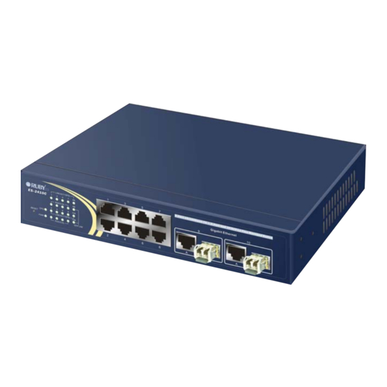
1-4. View of ES-2410C Fig. 1-1 Full View of ES-2410C with SFP/GBIC Module 1-4-1. User Interfaces on the Front Panel (Button, LEDs and Plugs) There are 8 TP Fast Ethernet ports and 2 slots for optional removable modules on the front panel of the switch. LED display area, locating on the front panel, contains a CPURUN, Power LED and 26 ports working status of the switch. -
Page 15: Led Indicators
• LED Indicators Color Function System LED Green Lit when CPU is on and good Green Lit when AC power is on and good Green Lit when LEDSET set on active mode Green Lit when LEDSET set on full-duplex mode Green Lit when LEDSET set on speed mode 10/100Mbps Ethernet TP Port 1 to 8 LED... -
Page 16: User Interfaces On The Rear Panel
AC power input socket for having the switch powered on or off. RS-232 DB-9 AC Line 100-240V 50/60 Hz Fig. 1-3 Rear View of ES-2410C 1-5. View of the Optional Modules In the switch, Port 9, 10 includes two types of media --- TP and SFP Fiber (LC, BiDi LC…);... - Page 17 Fig. 1-5 Front View of 1000Base-LX BiDi LC, SFP Fiber Transceiver In the switch, Port 9, 10 includes two types of media --- TP and GBIC Fiber (SC, BiDi SC…); this port supports 10/100/1000Mbps TP or 1000Mbps GBIC Fiber with auto-detected function. 1000Mbps GBIC Fiber transceiver is used for high- speed connection expansion;...
-
Page 18: Installation
At the beginning, please do first: ⇒ Wear a grounding device to avoid the damage from electrostatic discharge • Installing Optional SFP/GBIC Fiber Transceivers to the ES-2410C L2 Plus Managed Switch Note: If you have no modules, please skip this section. - Page 19 • TP Port and Cable Installation ⇒ In the switch, TP port supports MDI/MDI-X auto-crossover, so both types of cable, straight-through (Cable pin-outs for RJ-45 jack 1, 2, 3, 6 to 1, 2, 3, 6 in 10/100M TP; 1, 2, 3, 4, 5, 6, 7, 8 to 1, 2, 3, 4, 5, 6, 7, 8 in Gigabit TP) and crossed-over (Cable pin-outs for RJ-45 jack 1, 2, 3, 6 to 3, 6, 1, 2) can be used.
-
Page 20: Installing Chassis To A 9-Inch Wiring Closet Rail
2-1-2. Installing Chassis to a 9-Inch Wiring Closet Rail Fig. 2-2 Caution: Allow a proper spacing and proper air ventilation for the cooling fan at both sides of the chassis. ⇒ Wear a grounding device for electrostatic discharge. ⇒ Screw the mounting accessory to the front side of the switch (See Fig. 2-2). ⇒... - Page 21 ⎯ Gigabit Fiber with multi-mode LC SFP module ⎯ Gigabit Fiber with single-mode LC SFP module ⎯ Gigabit Fiber with BiDi LC 1310nm SFP module ⎯ Gigabit Fiber with BiDi LC 1550nm SFP module The following table lists the types of fiber that we support and those else not listed here are available upon request.
-
Page 22: Switch Cascading In Topology
2-1-3-3. Switch Cascading in Topology • Takes the Delay Time into Account Theoretically, the switch partitions the collision domain for each port in switch cascading that you may up-link the switches unlimitedly. In practice, the network extension (cascading levels & overall diameter) must follow the constraint of the IEEE 802.3/802.3u/802.3z and other 802.1 series protocol specifications, in which the limitations are the timing requirement from physical signals defined by 802.3 series specification of Media Access Control (MAC) and PHY, and timer from some... - Page 23 communicate each other directly is bounded in the same VLAN area. Here VLAN area is defined by what VLAN you are using. The switch supports both port-based VLAN and tag-based VLAN. They are different in practical deployment, especially in physical location. The following diagram shows how it works and what the difference they are.
-
Page 24: Configuring The Management Agent Of Es-2410C
RS-232 console, CLI, and Web. Users can use any one of them to monitor and configure the switch. You can touch them through the following procedures. Section 2-1-4-1: Configuring the Management Agent of ES-2410C through the Serial RS-232 Port... - Page 25 RS-232 DB-9 Connector AC Line 100-240V 50/60 Hz RS-232 ES-2410C L2 Plus Managed Switch Default IP Setting: IP address = 192.168.1.1 Subnet Mask = 255.255.255.0 Default Gateway = 192.168.1.254 RS-232 cable with female DB-9 connector at both ends Fig. 2-7...
-
Page 26: Configuring The Management Agent Of Es-2410C Through The Ethernet Port
Network Management System (NMS). Fig. 2-8 the Login Screen for CLI 2-1-4-2. Configuring the Management Agent of ES-2410C through the Ethernet Port There are three ways to configure and monitor the switch through the switch’s Ethernet port. -
Page 27: Ip Address Assignment
• Managing ES-2410C through Ethernet Port Before you communicate with the switch, you have to finish first the configuration of the IP address or to know the IP address of the switch. Then, follow the procedures listed below. 1. Set up a physical path between the configured the switch and a PC by a qualified UTP Cat. - Page 28 32 bits Network identifier Host identifier Fig. 2-11 IP address structure With the classful addressing, it divides IP address into three classes, class A, class B and class C. The rest of IP addresses are for multicast and broadcast. The bit length of the network prefix is the same as that of the subnet mask and is denoted as IP address/X, for example, 192.168.1.0/24.
-
Page 29: Subnet
Class D and E: Class D is a class with first 4 MSB (Most significance bit) set to 1-1-1-0 and is used for IP Multicast. See also RFC 1112. Class E is a class with first 4 MSB set to 1-1-1-1 and is used for IP broadcast. According to IANA (Internet Assigned Numbers Authority), there are three specific IP address blocks reserved and able to be used for extending internal network. -
Page 30: Table
In this diagram, you can see the subnet mask with 25-bit long, 255.255.255.128, contains 126 members in the sub-netted network. Another is that the length of network prefix equals the number of the bit with 1s in that subnet mask. With this, you can easily count the number of IP addresses matched. -
Page 31: Default Gateway
Default gateway: For the routed packet, if the destination is not in the routing table, all the traffic is put into the device with the designated IP address, known as default router. Basically, it is a routing policy. The gateway setting is used for Trap Events Host only in the switch. -
Page 32: Typical Applications
2-2. Typical Applications The ES-2410C implements 8 Fast Ethernet TP ports with auto MDIX and 2 Gigabit dual media ports with SFP/GBIC for removable module supported comprehensive fiber types of connection, including LC, BiDi LC for SFP and LC/SC, BiDi LC/SC for GBIC. For more details on the specification of the switch, please refer to Appendix A. - Page 33 Fig. 2-13 is a system wide basic reference connection diagram. This diagram demonstrates how the switch connects with other network devices and hosts. Fig. 2-14 Peer-to-peer Network Connection Fig. 2-15 Office Network Connection Publication date: Jan., 2009 Revision A1...
-
Page 34: Operation Of Web-Based Management
3. Operation of Web-based Management This chapter instructs you how to configure and manage the ES-2410C through the web user interface it supports, to access and manage the 8 10/100Mbps TP + 2 Gigabit dual media ports with TP/SFP(or GBIC)Fiber management Ethernet switch. - Page 35 To optimize the display effect, we recommend you use Microsoft IE 6.0 above, Netscape V7.1 above or FireFox V1.00 above and have the resolution 1024x768. The switch supported neutral web browser interface. In Fig. 3-2, for example, left section is the whole function tree with web user interface and we will travel it through this chapter.
-
Page 36: Web Management Home Overview
3-1. Web Management Home Overview After you login, the switch shows you the system information as Fig. 3-2. This page is default and tells you the basic information of the system, including “Model Name”, “System Description”, “Location”, “Contact”, “Device Name”, “System Up Time”, “Current Time”, “BIOS Version”, “Firmware Version”, “Hardware-Mechanical Version”, “Serial Number”, “Host IP Address”, “Host MAC Address”, “Device Port”, “RAM Size”... - Page 37 Fig. 3-3 port detail information In Fig. 3-3, it shows the basic information of the clicked port. With this, you’ll see the information about the port status, traffic status and bandwidth rating for egress and ingress respectively. ⎯ On the left-top corner, there is a pull-down list for Auto Logout. For the sake of security, we provide auto-logout function to protect you from illegal user as you are leaving.
- Page 38 Root System DHCP Snooping IP-MAC Binding Port Loop Detection SNMP DHCP Boot Multicast VLAN MAC Table GVRP MSTP Trunk 802.1X Alarm Configuration Security Bandwidth Diagnostics TFTP Server Firmware Upgrade Reboot Logout Publication date: Jan., 2009 Revision A1...
-
Page 39: System Information
You can configure this parameter through the device’s user interface or SNMP. Device name: The name of the switch. User-defined. Default is ES-2410C. System up time: The time accumulated since this switch is powered up. Its format is day, hour, minute, second. - Page 40 Host MAC address: It is the Ethernet MAC address of the management agent in this switch. Device Port: Show all types and numbers of the port in the switch. RAM size: The size of the DRAM in this switch. Flash size: The size of the flash memory in this switch.
-
Page 41: Ip Configuration
3-1-2. IP Configuration IP configuration is one of the most important configurations in the switch. Without the proper setting, network manager will not be able to manage or view the device. The switch supports both manual IP address setting and automatic IP address setting via DHCP server. - Page 42 Users can configure the IP settings and fill in new values if users set the DHCP function “Disable”. Then, click <Apply> button to update. When DHCP is disabled, Default: 192.168.1.1 If DHCP is enabled, this field is filled by DHCP server and will not allow user manually set it any more.
- Page 43 The switch supports DNS client function to re-route the mnemonic name address to DNS server to get its associated IP address for accessing Internet. User can specify a DNS IP address for the switch. With this, the switch can translate a mnemonic name address into an IP address. There are two ways to specify the IP address of DNS.
-
Page 44: Time Configuration
3-1-3. Time Configuration The switch provides manual and automatic ways to set the system time via NTP. Manual setting is simple and you just input “Year”, “Month”, “Day”, “Hour”, “Minute” and “Second” within the valid value range indicated in each item. If you input an invalid value, for example, 61 in minute, the switch will clamp the figure to NTP is a well-known protocol used to synchronize the clock of the switch system time over a network. - Page 45 Daylight Saving: Daylight saving is adopted in some countries. If set, it will adjust the time lag or in advance in unit of hours, according to the starting date and the ending date. For example, if you set the day light saving to be 1 hour. When the time passes over the starting time, the system time will be increased one hour after one minute at the time since it passed over.
- Page 46 Fig. 3-5 Publication date: Jan, 2009 Revision A1...
-
Page 47: Account Configuration
3-1-4. Account Configuration In this function, only administrator can create, modify or delete the username and password. Administrator can modify other guest identities’ password without confirming the password but it is necessary to modify the administrator-equivalent identity. Guest-equivalent identity can modify his password only. Please note that you must confirm administrator/guest identity in the field of Authorization in advance before configuring the username and password. -
Page 48: Management Security
3-1-5. Management Security Through the management security configuration, the manager can do the strict setup to control the switch and limit the user to access this switch. The following rules are offered for the manager to manage the switch: Rule 1) : When no lists exists, then it will accept all connections. Accept ----------------------------------------------------------------------- Rule 2) : When only “accept lists”... - Page 49 Function name: Management Security Configuration Function description: The switch offers Management Security Configuration function. With this function, the manager can easily control the mode that the user connects to the switch. According to the mode, users can be classified into two types: Those who are able to connect to the switch (Accept) and those who are unable to connect to the switch (Deny).
- Page 50 Access Type: supports two kinds of options The switch for managed valid Access Type including “Any” and “Custom”. Default is “Any”. “Http”, “Telnet” and “SNMP” are three ways for the access and managing the switch in case that” Custom” had been chosen. Action: supports two kinds of options The switch...
-
Page 51: Virtual Stack
3-1-6. Virtual Stack Function name: Virtual Stack Function description: Virtual Stack Management(VSM) is the group management function. Through the proper configuration of this function, switches in the same LAN will be grouped automatically. And among these switch, one switch will be a master machine, and the others in this group will become the slave devices. - Page 52 Parameter description: State: It is used for the activation or de-activation of VSM. Default is Enable. Role: The role that the switch would like to play in virtual stack. Two types of roles, including master and slave are offered for option. Default is Master. Group ID: It is the group identifier (GID) which signs for VSM.
-
Page 53: Dhcp Snooping
3-1-7. DHCP Snooping DHCP Snooping Config Trust Group Lease List Counter Function name: Config Function description: The addresses assigned to DHCP clients on unsecure ports can be carefully controlled using the dynamic bindings registered with DHCP Snooping. DHCP snooping allows a switch to protect a network from rogue DHCP servers or other devices which send port-related information to a DHCP server. - Page 54 Fig. 3-10 Parameter description: State: It is used for the activation or de-activation of DHCP snooping. Default is disable. Per Port Client Count Setup: It is used for per port client count setup. Default is 128 Function name: DHCP Snooping Trust Group Config Fig.
- Page 55 Parameter description: Trust Port 1:If DHCP snooping is enabled globally, and also enabled on the VLAN where the DHCP packet is received, all DHCP packets are forwarded for a trusted por. It set a trust port 1. available port from 1 to 10. Default is disable Trust port 2 : It set a trust port 2.
- Page 56 Function name: DHCP Snooping Lease List Fig. 3-12 Parameter description: MAC: To show the DHCP snooping client’s MAC address. IP:To show the DHCP snooping client’s IP address. Port:To show the DHCP snooping client’s port. VID: To show the DHCP snooping client’s VLAN ID. Lease:To show the DHCP snooping client’s lease.
-
Page 57: Ip-Mac Binding
3-2. IP-MAC Binding The IP network layer uses a four-byte address. The Ethernet link layer uses a six-byte MAC address. Binding these two address types together allows the transmission of data between the layers. The primary purpose of IP-MAC binding is to restrict the access to a switch to a number of authorized users. - Page 58 Fig. 3-15 Parameters description: Current User List: The maximum number of IP-MAC binding client table is 512 entries. The maximum number of IP-MAC Binding server table is 64 entries. The entry number and delete icon when you need to delete the entry then you need to click the icon to delete it..
-
Page 59: Port Configuration
3-3. Port Configuration Four functions, including Port Status, Port Configuration, Simple Counter and Detail Counter are contained in this function folder for port monitor and management. Each of them will be described in detail orderly in the following sections. Port Configuration Status Configuration Description... - Page 60 Parameter Description: Port No: Display the port number. The number is 1 – 8. Both port 9 and 10 are optional modules. Media: Show the media type adopted in all ports. The Port 9 and Port 10 are optional modules, which support either fiber or UTP media with either Gigabit Ethernet (1000Mbps) or 10/100Mbps Fast Ethernet port.
- Page 61 duplex. In port 9 and port 10, if the media is 1000Mbps with TP media, it will show the combinations of 10/100M and Full/Half duplex, 1000Mbps and Full duplex only. If the media is 1000Mbps with fiber media, it will show only 1000M/Full duplex.
- Page 62 Baud Rate: Display the maximum baud rate of the fiber module supported, for instance, 10M, 100M, 1G and so on. Vendor OUI: Display the Manufacturer's OUI code which is assigned by IEEE. Vendor Name: Display the company name of the module manufacturer. Vendor P/N: Display the product name of the naming by module manufacturer.
-
Page 63: Port Configuration
3-3-2. Port Configuration Port Configuration is applied to change the setting of each port. In this configuration function, you can set/reset the following functions. All of them are described in detail below. Fig. 3-18 Function name: Port Configuration Function description: It is used to set each port’s operation mode. - Page 64 mode, 10/100/1000Mbps, and duplex mode, full duplex and half duplex. The following table summarized the function the media supports. Media type NWay Speed Duplex 100M TP ON/OFF 10/100M Full/Half 1000M TP ON/OFF 10/100/1000M Full for all, Half for 10/100 1000M Fiber ON/OFF 1000M Full...
-
Page 65: Description
3-2-3. Description The function of Description provides the port description about the alias of the port. It will help manager to identify the Port. Function name: Description Function description: To type the port alias for port description. Identify the port property and what is the port purpose. -
Page 66: Simple Counter
3-2-4. Simple Counter The function of Simple Counter collects any information and provides the counting about the traffic of the port, no matter the packet is good or bad. In the Fig. 3-13, the window can show all ports’ counter information at the same time. -
Page 67: Detail Counter
3-3-5. Detail Counter The function of Detail Counter collects any information and provides the counting about the traffic of the port, no matter the packet is good or bad. In the Fig. 3-21, the window can show only one port counter information at the same time. - Page 68 Rx Broadcast Packets: Show the counting number of the received broadcast packet. Rx Multicast Packets: Show the counting number of the received multicast packet. Rx Pause Packets: Show the counting number of the received pause packet. Tx Collisions: Number of collisions transmitting frames experienced. Tx Single Collision: Number of frames transmitted that experienced exactly one collision.
- Page 69 Tx Packets: The counting number of the packet transmitted. TX Octets: Total transmitted bytes. Tx Unicast Packets: Show the counting number of the transmitted unicast packet. Tx Broadcast Packets: Show the counting number of the transmitted broadcast packet. Tx Multicast Packets: Show the counting number of the transmitted multicast packet.
-
Page 70: Loop Detection
3-4. Loop Detection The loop detection is used to detect the presence of traffic. When switch receives packet’s(looping detection frame) MAC address the same as oneself from port, show Loop detection happens. The port will be locked when it received the looping detection frames. -
Page 71: Snmp Configuration
3-5. SNMP Configuration Any Network Management System (NMS) running the Simple Network Management Protocol (SNMP) can manage the Managed devices equipped with SNMP agent, provided that the Management Information Base (MIB) is installed correctly on the managed devices. The SNMP is a protocol that is used to govern the transfer of information between SNMP manager and agent and traverses the Object Identity (OID) of the management Information Base (MIB), described in the form of SMI syntax. - Page 72 Default SNMP function : Enable Default community name for GET: public Default community name for SET: private Default community name for Trap: public Default Set function : Enable Default trap host IP address: 0.0.0.0 Default port number :162 Trap: In the switch, there are 6 trap hosts supported. Each of them has its own community name and IP address;...
-
Page 73: Dhcp Boot
3-6. DHCP Boot The DHCP Boot function is used to spread the request broadcast packet into a bigger time frame to prevent the traffic congestion due to broadcast packets from many network devices which may seek its NMS, boot server, DHCP server and many connections predefined when the whole building or block lose the power and then reboot and recover. -
Page 74: Multicast
3-7. Multicast The function, is used to establish the multicast groups to forward the multicast packet to the member ports, and, in nature, avoids wasting the bandwidth while IP multicast packets are running over the network. This is because a switch that does not support IGMP or IGMP Snooping can not tell the multicast packet from the broadcast packet, so it can only treat them all as the broadcast packet. -
Page 75: Igmp Setting
3-7-1. IGMP Setting Function name: IGMP Setting Function description: IGMP is used to snoop the status of IP multicast groups and display its associated information in both tagged VLAN and non-tagged VLAN networks. Enabling IGMP with either passive or active mode, you can monitor the IGMP snooping information, which contains the multicast member list with the multicast groups, VID and member port. - Page 76 General Query Interval : The general query interval is the amount of time in seconds between IGMP General Query messages sent by the router (if the router is the querier on this subnet). Available value: 1-2000 sec General Query Max Response Time : The Maximum Response Time field is only used in general or group- specific query messages.
-
Page 77: Igmp Vlan
3-7-2. IGMP VLAN Function name: IGMP VLAN Function description: Specify the a static connection to a multicast router for the VLAN. Parameter description: VID: To Set specify the IGMP snooping VLAN ID for each multicast group. Fig. 3-26 Publication date: Jan., 2009 Revision A1... -
Page 78: Mvr Setting
3-7-3. MVR Setting Function name: MVR Setting Function description: Multicast VLAN Registration (MVR) routes packets received in a multicast source VLAN to one or more receive VLANs. Clients are in the receive VLANs and the multicast server is in the source VLAN. Multicast routing has to be disabled when MVR is enabled. -
Page 79: Group Filtering
3-7-4. Group Filtering Function name: Group Filtering Function description: The Group Filtering function allows the Multicast VLAN Registration to set up the IP multicast group filtering conditions. IGMP join behavior that meet the items you set up will be joined or formed the multicast group. Fig. -
Page 80: Vlan
3-8. VLAN The switch supports Tag-based VLAN (802.1q) and Port-based VLAN Support 256 active VLANs and VLAN ID 1~4094. VLAN configuration is used to partition your LAN into small ones as your demand. Properly configuring it, you can gain not only improving security and increasing performance but greatly reducing VLAN management. - Page 81 Port-based: Port-based VLAN is defined by port. Any packet coming in or outgoing from any one port of a port-based VLAN will be accepted. No filtering criterion applies in port-based VLAN. The only criterion is the physical port you connect to. For example, for a port-based VLAN named PVLAN-1 contains port members Port 1&2&3&4.
- Page 82 Except Port 10, each port of the switch cannot transmit packets with each other. Each port groups a VLAN with Port 10, thus, total 8 groups consisting of 2 members are formed. 9&10: Except Port 9 and Port 10, each port of the switch cannot transmit packets with each other.
-
Page 83: Tag-Based Group
3-8-2. Tag-based Group Function name: Tag-based Group Configuration Function description: It shows the information of existed Tag-based VLAN Groups. You can also easily create, edit and delete a Tag-based VLAN group by pressing <Add>, <Edit> and <Delete> function buttons. User can add a new VLAN group by inputting a new VLAN name and VLAN ID after pressing <Add>... - Page 84 Add Group: Input the VLAN name, VID and then choose the member by ticking the check box beside the port No. to create a new Tag-based VLAN. As to the parameter of Untag, it stands for an egress rule of the port. If you tick the check box beside the port No., packets with this VID outgoing from this port will be untagged.
-
Page 85: Pvid
3-8-3. PVID Function name: PVID Function description: In PVID Setting, user can input VID number to each port. The range of VID number is from 1 to 4094. User also can choose ingress filtering rule (Rule 2) to each port. The Ingress Filtering Rule 2 is “drop untagged frame”. While Rule 2 is enabled, the port will discard all Untagged-frames. - Page 86 Drop Untag: Drop untagged frame. You can configure a given port to accept all frames (Tagged and Untagged) or just receive tagged frame. If the former is the case, then the packets with tagged or untagged will be processed. If the later is the case, only the packets carrying VLAN tag will be processed, the rest packets will be discarded.
-
Page 87: Port-Based Group
3-8-4. Port-based Group Function name: Port-based Group Configuration Function description: It shows the information of the existed Port-based VLAN Groups. You can easily create, edit and delete a Port-based VLAN group by pressing <Add>, <Edit> and <Delete> function buttons. User can add a new VLAN group by inputting a new VLAN name. - Page 88 Fig. 3-35 Delete Group: Just press the <Delete> button to remove the selected group entry from the Port-based group table. Fig. 3-36 Edit a group: Just select a group entry and press the <Edit> button, then you can modify a group‘s description and member set. Publication date: Jan, 2009 Revision A1...
-
Page 89: Management Vlan
3-8-5. Management VLAN Function name: Management VLAN Function Description: Fig. 3-37 Parameter description: State: It works when the tag-based mode is chosen. When this function is enabled, only the tagged packets with this VID can manage the switch. VID: Valid range 1~4094. Publication date: Jan., 2009 Revision A1... -
Page 90: Mac Table
3-9. MAC Table MAC Table Configuration gathers many functions, including MAC Table Information, MAC Table Maintenance, Static and MAC Alias, which cannot be categorized to some function type. They are described below. Function name: MAC Table Information Function Description: Display the static or dynamic learning MAC entry and the state for the selected port. - Page 91 Next Page: Move to the next page. Alias: The Alias of the searched entry. MAC Address: The MAC address of the searched entry. Port: The port that exists in the searched MAC Entry. VID: VLAN Group that MAC Entry exists. State: Display the method that this MAC Entry is built.
- Page 92 Parameter description: Aging Time: Delete a MAC address idling for a period of time from the MAC Table, which will not affect static MAC address. Range of MAC Address Aging Time is 10-1000000 seconds. The default Aging Time is 300 seconds. Learning Limit: To set up the maximum amount of MAC that each port can learn.
- Page 93 Parameter description: MAC: It is a six-byte long Ethernet hardware address and usually expressed by hex and separated by hyphens. For example, 00 – 40 - C7 - D6 – 00 - 01 VID: VLAN identifier. This will be filled only when tagged VLAN is applied. Valid range is 1 ~ 4094.
- Page 94 Fig. 3-41 Function name: MAC Alias Create/Edit or Delete Function description: In the MAC Alias function, MAC Alias Add/Edit function is used to let you add or modify an association between MAC address and a plain English name. User can click <Create/Edit> button to add a new record with name. As to MAC Alias Delete function is used to let you remove an alias name to a MAC address.
- Page 95 Function name: Port Security Function description: In its most basic form, the Port Security feature remembers the Ethernet MAC address connected to the switch port and allows only that MAC address to communicate on that port. If any other MAC address tries to communicate through the port, port security will disable the port.
- Page 96 Parameter description: You can select which port you want to set static MAC table. Press the Add to create a new Static MAC address entry. Fig. 3-44 MAC Address: It is a six-byte long Ethernet hardware address and usually expressed by hex and separated by hyphens.
-
Page 97: Gvrp Configuration
3-10. GVRP Configuration GVRP is an application based on Generic Attribute Registration Protocol (GARP), mainly used to automatically and dynamically maintain the group membership information of the VLANs. The GVRP offers the function providing the VLAN registration service through a GARP application. It makes use of GARP Information Declaration (GID) to maintain the ports associated with their attribute database and GARP Information Propagation (GIP) to communicate among switches and end stations. - Page 98 Join Time: Used to declare the Join Time in unit of centisecond. Valid time range: 20 –100 centisecond, Default: 20 centisecond. Leave Time: Used to declare the Leave Time in unit of centisecond. Valid time range: 60 –300 centisecond, Default: 60 centisecond. Leave All Time: A time period for announcement that all registered device is going to be de-registered.
- Page 99 Disabled: In this mode, the switch dynamic VLAN will be created when this port received GVRP PDU. The default setting is Normal. Enabled: In this mode, the switch does not create dynamic VLAN when this port received GVRP PDU. Except received dynamic VLAN message of the GVRP PDU is an existed static VLAN in the switch, this port will be added into the static VLAN members dynamically.
- Page 100 JoinEmpty Message Packets: Number of GARP BPDU with Join Empty message is received by the GARP application. JoinIn Message Packets: Number of GARP BPDU with Join In message is received by the GARP application. LeaveEmpty Message Packets: Number of GARP BPDU with Leave Empty message is received by the GARP application.
- Page 101 Function name: GVRP Group Information Function description: To show the dynamic group member and their information. Fig. 3-47 Parameter description: Current Dynamic Group Number: The number of GVRP group that are created currently. VID: VLAN identifier. When GVRP group creates, each dynamic VLAN group owns its VID.
-
Page 102: Stp Configuration
3-11. STP Configuration The Spanning Tree Protocol (STP) is a standardized method (IEEE 802.1D) for avoiding loops in switched networks. When STP is enabled, ensure that only one path is active between any two nodes on the network at a time. User can enable Spanning Tree Protocol on switch’s web management and then set up other advanced items. - Page 103 Show the current root bridge priority. Root Port: Show port number connected to root bridge with the lowest path cost. Root Path Cost: Show the path cost between the root port and the designated port of the root bridge. Current Max. Age: Show the current root bridge maximum age time.
-
Page 104: Stp Configuration
If you want to have the ES-2410C as root bridge, you can set this value lower than that of bridge in the LAN. The valid value is 0 ~ 61440. The default is 32768. - Page 105 Max. Age: When the ES-2410C is the root bridge, the whole LAN will apply this figure set by this switch as their maximum age time. When a bridge received a BPDU originated from the root bridge and if the message age conveyed in the BPDU exceeds the Max.
-
Page 106: Stp Port Configuration
3-11-3. STP Port Configuration Function name: STP Port Setting Function description: In the STP Port Setting, one item selection and five parameters settings are offered for user’s setup. User can disable and enable each port by selecting each Port Status item. User also can set “Path Cost” and “Priority” of each port by filling in the desired value and set “Admin Edge Port”... - Page 107 Configured Path Cost: The range is 0 – 200,000,000. In the switch, if path cost is set to be zero, the STP will get the recommended value resulted from auto-negotiation of the link accordingly and display this value in the field of Path Cost Status.
- Page 108 Default: Auto M Check: Migration Check. It forces the port sending out an RSTP BPDU instead of a legacy STP BPDU at the next transmission. The only benefit of this operation is to make the port quickly get back to act as an RSTP port. Click <M Check>...
-
Page 109: Mstp Configuration
3-12. MSTP Configuration The implementation of MSTP is according to IEEE 802.1Q 2005 Clause 13 – Multiple Spanning Tree Protocol. MSTP allows frames assigned to different VLANs to follow separate paths, each based on an independent Multiple Spanning Tree Instance (MSTI), within Multiple Spanning Tree (MST) Regions composed of LANs and or MST Bridges. -
Page 110: Region Config
3-12-2 Region Config Function name: MSTP Region Config Function description: To configure the basic identification of a MSTP bridge. Bridges participating in a common MST region must have the same Region Name and Revision Level. Fig. 3-52 Parameter description: Region Name: 0-32 characters.(A variable length text string encoded within a fixed field of 32 octets , conforming to RFC 2271’s definition of SnmpAdminString.) Revision Level:... -
Page 111: Instance View
3-12-3 Instance View Function name: MSTP Instance Config Function description: Providing an MST instance table which include information(vlan membership of a MSTI ) of all spanning instances provisioned in the particular MST region which the bridge belongs to. Through this table, additional MSTP configuration data can be applied and MSTP status can be retrieved. - Page 112 Del All MSTI: Deleting all provisioned MSTIs at a time. Instance Configuration: Fig. 3-55 To provision spanning tree performance parameters per instance. Port Config: Fig. 3-56 To provision spanning tree performance parameters per instance per port. Instance Status: Fig. 3-57 To show the status report of a particular spanning tree instance.
- Page 113 Parameter description: Priority: The priority parameter used in the CIST(Common and Internal Spanning Tree) connection. 0 / 4096 / 8192 / 12288 / 16384 / 20480 / 24576 / 28672 / 32768 / 36864 / 40960 / 45056 / 49152 / 53248 / 57344 / 61440 MAX.
- Page 114 Priority: 0 / 16 / 32 / 48 / 64 / 80 / 96 / 112 / 128 / 144 / 160 / 176 / 192 / 208 / 224 / 240 The same definition as in the RSTP specification. But in MSTP, this parameter can be respectively applied to ports of CIST and ports of any MSTI.
- Page 115 Fig. 3-57 Parameter description: MSTP State: MSTP protocol is Enable or Disable. Force Version: It shows the current spanning tree protocol version configured. Bridge Max Age: It shows the Max Age setting of the bridge itself. Bridge Forward Delay: It shows the Forward Delay setting of the bridge itself. Bridge Max Hops: It shows the Max Hops setting of the bridge itself.
- Page 116 CIST EXTERNAL ROOT PATH COST: Root path cost value from the point of view of the bridge’s MST region. CIST ROOT PORT ID: The port ID of the bridge’s root port. In MSTP, peer port of a root port may reside in defferent MST region or in the same MST region.The first case indicates that the root port’s owner is the CIST regional root bridge.
- Page 117 Fig. 3-58 Parameter description: Port No: 1-10 Status: The forwarding status.Same definition as of the RSTP specification Possible values are “FORWARDING” , “LEARNING” , “DISCARDING” Status: The role that a port plays in the spanning tree topology. Possible values are “dsbl”(disable port) , ”alt”(alternate port) , “bkup”(backup port) , “ROOT”(root port) , “DSGN”(designated port) , “MSTR”(master port).
- Page 118 Restricted Role: Same as mentioned in “Port Config” Restricted Tcn: Same as mentioned in “Port Config” Publication date: Jan, 2009 Revision A1...
-
Page 119: Trunking Configuration
3-13. Trunking Configuration The Port Trunking Configuration is used to configure the settings of Link Aggregation. You can bundle more than one port with the same speed, full duplex and the same MAC to be a single logical port, thus the logical port aggregates the bandwidth of these ports. - Page 120 Function name: Port Setting/Status Function description: Port setting/status is used to configure the trunk property of each and every port in the switch system. Fig. 3-59 Parameter description: Method: This determines the method a port uses to aggregate with other ports. None: A port does not want to aggregate with any other port should choose this default setting.
- Page 121 Active LACP: This field is only referenced when a port’s trunking method is LACP. Active: An Active LACP port begins to send LACPDU to its link partner right after the LACP protocol entity started to take control of this port. Passive: A Passive LACP port will not actively send LACPDU out before it receives an LACPDU from its link partner.
- Page 122 Parameter description: Aggregator: It shows the aggregator ID (from 1 to 26) of every port. In fact, every port is also an aggregator, and its own aggregator ID is the same as its own Port No.. Method: Show the method a port uses to aggregate with other ports. Member Ports: Show all member ports of an aggregator (port).
- Page 123 Fig. 3-61 Function name: LACP System Configuration Function description: It is used to set the priority part of the LACP system ID. LACP will only aggregate together the ports whose peer link partners are all on a single system. Each system supports LACP will be assigned a globally unique System Identifier for this purpose.
-
Page 124: Configuration
3-14. 802.1x Configuration 802.1x port-based network access control provides a method to restrict users to access network resources via authenticating user’s information. This restricts users from gaining access to the network resources through a 802.1x-enabled port without authentication. If a user wishes to touch the network through a port under 802.1x control, he (she) must firstly input his (her) account name for authentication and waits for gaining authorization before sending or receiving any packets from a 802.1x-enabled port. - Page 125 The overview of operation flow for the Fig. 3-63 is quite simple. When Supplicant PAE issues a request to Authenticator PAE, Authenticator and Supplicant exchanges authentication message. Then, Authenticator passes the request to RADIUS server to verify. Finally, RADIUS server replies if the request is granted or denied.
- Page 126 Authentication server Fig. 3-64 Authenticator Supplicant A The Fig. 3-64 shows the procedure of 802.1x authentication. There are steps for the login based on 802.1x port access control management. The protocol used in the right side is EAPOL and the left side is EAP. At the initial stage, the supplicant A is unauthenticated and a port on switch acting as an authenticator is in unauthorized state.
- Page 127 When the authenticator PAE receives a Radius-Access-Accept, it will send an EAP-Success to the supplicant. At this time, the supplicant is authorized and the port connected to the supplicant and under 802.1x control is in the authorized state. The supplicant and other devices connected to this port can access the network.
- Page 128 Port Mode Port Control Authentication Port Status Disable Don’t Care Don’t Care Port Uncontrolled Multihost Auto Successful Port Authorized Multihost Auto Failure Port Unauthorized Multihost ForceUnauthorized Don’t Care Port Unauthorized Multihost ForceAuthorized Don’t Care Port Authorized Table 3-3 Function name: 802.1x State Setting Function description: This function is used to configure the global parameters for RADIUS...
- Page 129 Function name: 802.1x Mode Setting Function description: Set the operation mode of 802.1X for each port. In this device, it supports only Multi-host operation mode. Fig. 3-67 Parameter description: Port Number: Indicate which port is selected to configure the 802.1x operation mode. 802.1x Mode: 802.1x operation mode.
- Page 130 Function name: Port Security Management Function description: Shows each port status. In Multihost mode, it shows the port number and its status, authorized or unauthorized. Fig. 3-68 Parameter description: Disable Mode: When selecting Disable mode for a port in the function 802.1X Port Mode Configuration, the port is in the uncontrolled port state and does not apply 802.1X authenticator on it.
- Page 131 Function name: Param. Setting Function description: This function is used to configure the parameters for each port in 802.1x port security application. Refer to the following parameters description for details. Fig. 3-69 Parameter description: Port: It is the port number to be selected for configuring its associated 802.1x parameters which are Port control, reAuthMax, txPeriod, Quiet Period, reAuthEnabled, reAuthPeriod, max.
- Page 132 reAuthMax(1-10): The number of authentication attempt that is permitted before the port becomes unauthorized. Default: 2 txPeriod(1-65535 s): A time period to transmitted EAPOL PDU between the authenticator and the supplicant. Default: 30 Quiet Period(0-65535 s): A period of time during which we will not attempt to access the supplicant. Deafult: 60 seconds reAuthEnabled: Choose whether regular authentication will take place in this port.
-
Page 133: Alarm Configuration
3-15. Alarm Configuration Alarm Configuration Events Configuration Email/SMS Function name: Events Configuration Function description: The Trap Events Configuration function is used to enable the switch to send out the trap information while pre-defined trap events occurred. The switch offers 21 different trap events to users for switch management. The trap information can be sent out in three ways, including email, mobile phone SMS (short message system) and trap. - Page 134 Function name: Email/SMS Configuration Function description: Alarm configuration is used to configure the persons who should receive the alarm message via either email or SMS, or both. It depends on your settings. An email address or a mobile phone number has to be set in the web page of alarm configuration (See ).
- Page 135 Parameter description: Email: Mail Server: the IP address of the server transferring your email. Username: your username on the mail server. Password: your password on the mail server. Email Address 1 – 6: email address that would like to receive the alarm message.
-
Page 136: Configuration
3-16. Configuration The switch supports three copies of configuration, including the default configuration, working configuration and user configuration for your configuration management. All of them are listed and described below respectively. Default Configuration: This is Rubytech’s setting and cannot be altered. In Web UI, two restore default functions are offered for the user to restore to the default setting of the switch. -
Page 137: Save/Restore
3-16-1. Save/Restore Function name: Save As Start Configuration Function description: Save the current configuration as a start configuration file in flash memory. Fig. 3-73 Function name: Save As User Configuration Function description: Save the current configuration as a user configuration file in flash memory. Fig. - Page 138 Function name: Restore Default Configuration (includes default IP address) Function description: Restore Default Configuration function can retrieve Rubytech’s setting to replace the start configuration. And the IP address of the switch will also be restored to 192.168.1.1. Fig. 3-75 Function name: Restore Default Configuration (excludes current IP address) Function description: Restore Default Configuration function can retrieve Rubytech’s setting to...
- Page 139 Function name: Restore User Configuration Function description: Restore User Configuration function can retrieve the previous confirmed working configuration stored in the flash memory to update start configuration. When completing to restore the configuration, the system’s start configuration is updated and will be changed its system settings after rebooting the system. Fig.
-
Page 140: Config File
3-16-2. Config File Function name: Config File Function description: With this function, user can back up or reload the config files of Save As Start or Save As User via TFTP. Fig. 3-78 Parameter description: Export File Path: Export Start: Export Save As Start’s config file stored in the flash. -
Page 141: Security
3-17. Security Function name: Mirror Configuration Function description: Mirror Configuration is to monitor the traffic of the network. For example, we assume that Port A and Port B are Monitoring Port and Monitored Port respectively, thus, the traffic received by Port B will be copied to Port A for monitoring. - Page 142 Function name: Isolated Group Function description: Isolated Group function can let the port be independent of other ports in the Isolated group, and the communication is also forbidden between these ports. But, the ports of the Isolated group are still able to communicate with the ports of the non-Isolated group.
-
Page 143: Bandwidth Management
3-18. Bandwidth Management Function name: Ingress Bandwidth Setting Function description: Ingress Bandwidth Setting function is used to set up the limit of Ingress bandwidth for each port. Fig. 3-81 Parameter description: Port No.: Choose the port that you would like this function to work on it. Valid range of the port is 1~10. - Page 144 Function name: Egress Bandwidth Setting Function description: Egress Bandwidth Setting function is used to set up the limit of Egress bandwidth for each port. Fig. 3-82 Parameter description: Port No.: Choose the port that you would like this function to work on it. Valid range of the port is 1~10.
- Page 145 Function name: Storm Function description: Bandwidth Management function is used to set up the limit of Ingress and Egress bandwidth for each port. Fig. 3-83 Parameter description: Storm Type: Disable: Disable the function of the bandwidth storm control. BC (Broadcast Storm Control): Enable the function of bandwidth storm control for broadcast packets.
- Page 146 MC (Multicast Storm Control): Enable the function of bandwidth storm control for multicast packets. BC, MC (Broadcast, Multicast Storm Control): Enable the function of bandwidth storm control for broadcast and multicast Storm packets in transmission. UC, MC (Unknown Unicast, Multicast Storm Control): Enable the function of bandwidth storm control for Unknown Unicast and multicast Storm packets in transmission.
-
Page 147: Qos(Quality Of Service) Configuration
3-19. QoS(Quality of Service) Configuration The switch supports 5 kinds of QoS, are as follows, MAC Priority, 802.1p Priority, IP TOS Priority, and DiffServ DSCP Priority. Port Based Priority has a special name called VIP Port in the switch. Any packets enter VIP Port will have highest transmitting priority. - Page 148 Function name: QoS Global Setting Function description: When you want to use QoS function, please enable QoS Mode in advance. Then you can use MAC Priority, 802.1p Priority, IP TOS Priority, DiffServ DSCP Priority, or VIP Port functions and take effect. In this function, you can Enable QoS Mode.
- Page 149 Weight (1~55): Over here, you can make an arrangement to Weight values of Queue 0 to Queue 3. The range of Weight you can set is 1~55. In default, the weight of Queue 0 is 1, the weight of Queue 1 is 2, the weight of Queue 2 is 4, and the weight of Queue 3 is 8.
- Page 150 Parameter description: 802.1p Priority Mapping: Each Priority can select any of Queue 0 ~ Queue 3. In Default, Priority 0 is mapping to Queue 0, Priority 1 is mapping to Queue 0, Priority 2 is mapping to Queue 1, Priority 3 is mapping to Queue 1, Priority 4 is mapping to Queue 2, Priority 5 is mapping to Queue 2, Priority 6 is mapping to Queue 3, and Priority 0 is mapping to Queue 3.
-
Page 151: Acl
3-20. ACL The ES-2410C switch access control list (ACL) is probably the most commonly used object in the IOS. It is used for packet filtering but also for selecting types of traffic to be analyzed, forwarded, or influenced in some way. - Page 152 Parameter description: To add new access control rule on switch. You must configure the parameters what described later when you add the new access control rule. Edit/ Show: To modify or monitor the access control configuration rule on switch. Delete: To delete existed access control rule on switch.
- Page 153 ACL Configuration: To add a new ACL rule on switch. ACL name: To add a new ACL rule name, A name is composed of any letter (A-Z, a-z) and digit (0-9) with maximal 8 characters. Ingress Port Map: To evoke the ingress ports to join the access control rule. port number is 1~10 or all.
- Page 154 Ethernet Type: Fig. 3-91 To droll “Ethernet Type” bar and option “any”, “ IPv4”, “ ARP” and “ Specific” for ACL requirement. Any: It is including all frame type IPv4: It is including all IPv4 protocol frame type ARP: It is including all ARP protocol frame type Specific: It is specific frame type Fig.
- Page 155 IPv4: To set the IPv4 packet filter function with ACLs, the parameters shown as below: Protocol : To droll the bar and you can elect “ Any”, “ICMP”, “ UDP”, “TCP” and “Other” Fig. 3-93 IPv4 TOS : To droll the bar and you can elect “ Any”, and “ Specific”. If you click “...
- Page 156 Fig. 3-80 TTL Range : To droll the bar and you can elect “ TTL=0”, “TTL=1”, “TTL=2-254” and “ TTL=255” and set the Time to live value range. Fig. 3-81 IPv4 DA/ SA : To droll the bar and you can elect “ Any”, “HOST” and “Network”. Fig.
- Page 157 Fig. 3-83 L4 Source port : To droll the bar and you can elect “ Any” and “Specific”. If you click “specific” then you need to set source port value. Fig. 3-84 Action: To set network packet filter includes “In-band” , “Out-band” and “Modify Packet for In/Out-Band”.
- Page 158 Fig. 3-85 Fig. 3-86 Fig. 3-87 Publication date: Jan, 2009 Revision A1...
- Page 159 Fig. 3-88 Fig. 3-89 Modify Packet for In/ Out-Band : Modify Packet -802.1P: To droll down the bar to elect “Any” and “Specific”. If you click the “ Specific” then you need to set 802.1p value in the field. default is 0 Fig.
- Page 160 Fig. 3-91 Rate Meter: To set rate meter function with the bandwidth parameter. The range is 64 to 1024000kbps. Fig. 3-92 Publication date: Jan, 2009 Revision A1...
-
Page 161: Diagnostics
3- 21. Diagnostics Five functions, including Diagnostics, Loopback Test, Ping Test, Auto Ping and Cable are contained in this function folder for device self-diagnostics. Each of them will be described in detail orderly in the following sections. Diagnostics Diag Loopback Test Ping Test Auto Ping Cable... - Page 162 Function name: Loopback Test Function description: In the Loopback Test function, there are two different loopback tests. One is Internal Loopback Test and the other is External Loopback Test. The former test function will not send the test signal outside the switch box. The test signal only wraps around in the switch box.
- Page 163 Parameter description: IP Address: An IP address with the version of v4, e.g. 192.168.1.1. Default Gateway: IP address of the default gateway. For more details, please see the section of IP address in Chapter 2. Fig. 3-95 Function name: Auto Ping Function description: Auto Ping function is a tool for detecting if the target device is alive or not through ICMP protocol which abounds with report messages.
- Page 164 Function name: Cable Function description: Cable function is a tool for detecting if the cable per port status is OK or not. report messages. The switch provides cable Test function to let you know that if the cable connect to a port is OK or not. Fig.
-
Page 165: Tftp Server
3- 22. TFTP Server Function name: TFTP Server Function description: Set up IP address of TFTP server. Parameter description: Specify the IP address where the TFTP server locates. Fill in the IP address of your TFTP server, then press <Apply> button to have the setting taken effect. Fig. -
Page 166: Log
3-23. Log This function shows the log data. The switch provides system log data for users. There are 16 private trap logs, 5 public trap logs. The switch supports total 120 log entries. For more details on log items, please refer to the section of Trap/Alarm Configuration and SNMP Configuration. -
Page 167: Firmware Upgrade
3-24. Firmware Upgrade Software upgrade tool is used to help upgrade the software function in order to fix or improve the function. The switch provides a TFTP client for software upgrade. This can be done through Ethernet. Function name: Firmware Upgrade Function description: The switch supports TFTP upgrade tool for upgrading software. -
Page 168: Reboot
3-25. Reboot We offer you many ways to reboot the switch, including power up, hardware reset and software reset. You can press the RESET button in the front panel to reset the switch. After upgrading software, changing IP configuration or changing VLAN mode configuration, then you must reboot to have the new configuration taken effect. -
Page 169: Logout
3-26. Logout You can manually logout by performing Logout function. In the switch, it provides another way to logout. You can configure it to logout automatically. Function name: Logout Function description: The switch allows you to logout the system to prevent other users from the system without the permission. -
Page 170: Operation Of Cli Management
4. Operation of CLI Management 4-1. CLI Management Refer to Chapter 2 for basic installation. The following description is the brief of the network connection. -- Locate the correct DB-9 null modem cable with female DB-9 connector. Null modem cable comes with the management switch. Refer to the Appendix B for null modem cable configuration. - Page 171 Fig. 4-1 Publication date: Jan., 2009 Revision A1...
- Page 172 4-2. Commands of CLI To see the commands of the mode, please input “?” after the prompt, then all commands will be listed in the screen. All commands can be divided into two categories, including global commands and local commands. Global commands can be used wherever the mode you are.
-
Page 173: Global Commands Of Cli
When you enter this command, your current position would move to the top mode. If you use this command in the top mode, you are still in the position of the top mode. Argument: None. Possible value: None. Example: ES-2410C # alarm ES-2410C (alarm)# events ES-2410C (alarm-events)# end ES-2410C # exit Syntax: exit Description: Back to the previous mode. - Page 174 Argument: None. Possible value: None. Example: ES-2410C# ip ES-2410C(ip)# help Commands available: ------------<< Local commands >>------------ disable dhcp Disable DHCP enable dhcp Enable DHCP, and set dns auto or manual...
- Page 175 Possible value: [#]: 1, 2, 3, …., 256 Example: ES-2410C (ip)# history Command history: 0. ? 1. trunk 2. exit 3. ES-2410C # trunk 4. ES-2410C (trunk)# exit 5. ES-2410C # 6. trunk 7. exit 8. alarm 9. events 10. end 11.
-
Page 176: Restore Default
Argument: None. Possible value: None. Example: ES-2410C# logout Managed Switch - ES-2410C Login: restore default Syntax: restore default Description: When you use this function in CLI, the system will show you the information “Do you want to restore the default IP address?(y/n)”. If you choose Y or y, the IP address will restore to default “192.168.1.1”. -
Page 177: Restore User
CLI would save your current configuration into the non-volatile FLASH. If you want the configuration still works after rebooting, save the configuration using the command ‘save stat’. Argument: None. Possible value: None. Example: ES-2410C # save start Saving start... Save Successfully ES-2410C # Publication date: Jan., 2009 Revision A1... -
Page 178: Save User
To save the current configuration as the user-defined configuration. When you enter this command, the CLI would save your current configuration into the non-volatile FLASH as user-defined configuration. Argument: None. Possible value: None. Example: ES-2410C # save user Saving user... Save Successfully ES-2410C # Publication date: Jan, 2009 Revision A1... -
Page 179: Local Commands Of Cli
<sec> : timer, range 0-65535 Possible value: <port range> : 1 to 26 <sec> : 0-65535, default is 60 Example: ES-2410C (802.1x)# set quiet-period 2 30 set reAuthEnabled Syntax: set reAuthEnabled <port-range> <ebl> Description: A constant that define whether regular reauthentication will take place on this port. - Page 180 Example: ES-2410C (802.1x)# set reAuthMax 2 2 set reAuthPeriod Syntax: set reAuthPeriod <port-range> <sec> Description: A constant that defines a nonzero number of seconds between periodic reauthentication of the supplicant. Argument: <port range> : syntax 1,5-7, available from 1 to 26 <sec>...
- Page 181 <port-number> : 1~65535, default 1812 <Accounting Service> : 0 for disable, 1 for enable <Accounting Server> : xxx.xxx.xxx.xxx <Accounting Port> :1~65535 Example: ES-2410C(802.1X)# set state 192.168.2.252 1812 winradius 1 192.168.2.252 ES-2410C(802.1X)# show state Radius Server : 192.168.2.252 Port Number : 1812...
-
Page 182: Show Mode
<port range> : syntax 1,5-7, available from 1 to 26 <sec> : timer, range 1-65535 Possible value: <port range> : 1 to 26 <sec> : 1-65535, default is 30 Example: ES-2410C (802.1x)# set txPeriod 2 30 show mode Syntax: show mode Description: To display the mode of each port. - Page 183 : 30 show security Syntax: show security Description: To display the status of each port. authentication Argument: None. Possible value: None. Example: ES-2410C (802.1x)# show security Port Mode Status ====== ============ ============== Disable Disable Disable Disable Disable Normal Unauthorized Disable...
- Page 184 Syntax: show state Description: To display the Radius server configuration. Argument: None. Possible value: None. Example: ES-2410C (802.1x)# show state Radius Server: 192.168.1.115 Port Number : 1812 Secret Key : WinRadius Publication date: Jan, 2009 Revision A1...
- Page 185 To create a new guest user. When you create a new guest user, you must type in password and confirm password. Argument: <name> : new account name Possible value: <name> : A string must be at least 5 character. Example: ES-2410C(account)# add aaaaa Password: Confirm Password: ES-2410C(account)# Syntax: del <name> Description: To delete an existing account.
- Page 186 To change the username and password of an existing account. Argument: <name> : existing user account Possible value: None. Example: ES-2410C(account)# modify aaaaa username/password: the length is from 5 to 15. Current username (aaaaa):bbbbb New password: Confirm password: Username changed successfully.
- Page 187 Description: To set up the email address. Argument: <#> : email address number, range: 1 to 6 <mail address> : email address Possible value: <#>: 1 to 6 Example: ES-2410C(alarm-email)# set mail-address 1 abc@mail.abc.com Publication date: Jan., 2009 Revision A1...
- Page 188 To set up the IP address of the email server. Argument: <ip>:email server ip address or domain name Possible value: None. Example: ES-2410C(alarm-email)# set server 192.168.1.6 set user Syntax: set user <username> Description: To set up the account of the email server.
- Page 189 <range>:del the range of email, sms and trap of events, syntax 1,5-7, available from 1 to 25 Possible value: <range>: 1~25 Example: ES-2410C(alarm-events)# del all 1-3 del email Syntax: del email <range> Description: To disable the email of the events.
- Page 190 To disable the trap of the events. Argument: <range>:del the range of trap, syntax 1,5-7, available from 1 to 25 Possible value: <range>: 1~25 Example: ES-2410C(alarm-events)# del trap 1-3 set all Syntax: set all <range> Description: To enable email, sms and trap of events.
-
Page 191: Set Trap
To enable the sms of the events. Argument: <range>:set the range of sms, syntax 1,5-7, available from 1 to 25 Possible value: <range>: 1~25 Example: ES-2410C(alarm-events)# set sms 1-3 set trap Syntax: set trap <range> Description: To enable the trap of the events. - Page 192 Description: The Show for alarm here is used to display the configuration of Trap, SMS or E-mail. Argument: None. Possible value: None. Example: ES-2410C (alarm)# show email Mail Server Username Password : **************** Email Address 1: Email Address 2: Email Address 3:...
- Page 193 19 Metro-mode Vlan Enabled 20 Module Inserted 21 Module Removed 22 Dual Media Swapped 23 Looping Detected 24 IP-MAC Binding Offered 25 IP-MAC Binding Released ES-2410C (alarm)# show sms SMS Server Username Password : **************** Mobile Phone 1: Mobile Phone 2:...
- Page 194 To add sms phone number. Argument: <#>: mobile phone number, range: 1 to 6 <phone-number>: phone number Possible value: <#>: 1 to 6 Example: ES-2410C(alarm-sms)# set phone-number 1 0968777777 ES-2410C(alarm-sms)# show SMS Server : 192.168.2.222 Username : thomas Password : ****************...
- Page 195 <ip> Description: To set up the IP address of sms server. Argument: <ip>: SMS server ip address or domain name Possible value: None. Example: ES-2410C(alarm-sms)# set server 192.168.1.7 ES-2410C(alarm-sms)# show SMS Server : 192.168.1.7 Username : ABC Password : ****************...
- Page 196 Mobile Phone 4: Mobile Phone 5: Mobile Phone 6: show Syntax: show Description: To display the configuration of SMS trap event. Argument: None. Possible value: None. Example: S-2226C(alarm-sms)# show SMS Server : 192.168.1.7 Username : ABC Password : **************** Mobile Phone 1: 0910380190 Mobile Phone 2: Mobile Phone 3: Mobile Phone 4:...
- Page 197 < rate>: 64-1024000(Kb). port 1-24: 64-102400(Kb); port 25-26: 64-1024000(Kb) Possible value: <range>: 1 to 26 <rate>: 64-102400(Kb) for port 1-24; 64-1024000(Kb) for port 25-26 Example: ES-2410C(bandwidth)# set egress 8-12 3780 ES-2410C(bandwidth)# show Port Ingress Rate(Kb) Egress Rate(Kb) Storm Type Storm Rate(Kb)
- Page 198 <rate>: 64-1024000(Kb). port 1-24: 64-102400(Kb); port 25-26: 64-1024000(Kb) Possible value: <range>: 1 to 26 <rate>: 64-102400(Kb) for port 1-24; 64-1024000(Kb) for port 25-26 Example: ES-2410C (bandwidth)# set ingress 1-16 100 ES-2410C(bandwidth)# show Port Ingress Rate(Kb) Egress Rate(Kb) Storm Type Storm Rate(Kb)
- Page 199 FE port: 64 - 102400 (Kbps) GE port: 64 - 1024000 (Kbps). Possible value: <range>: 1 to 26 <type> : 0 to 7 <rate>: 64- 1024000 (Kbps) Example: ES-2410C(bandwidth)# set storm 20 3 5000 ES-2410C(bandwidth)# show Port Ingress Rate(Kb) Egress Rate(Kb) Storm Type Storm Rate(Kb) ====== ================== ================= ============ ================ ….
- Page 200 ES-2410C(bandwidth)# show Syntax: show Description: To display all current settings of the bandwidth. Argument: None Possible value: None Example: ES-2410C(bandwidth)# show ES-2410C(bandwidth)# show Port Ingress Rate(Kb) Egress Rate(Kb) Storm Type Storm Rate(Kb) ====== ================== ================= ============ ================ …. 102400 102400...
- Page 201 102400 3776 DISABLE 102400 102400 3776 DISABLE 102400 102400 102400 DISABLE 102400 102400 102400 DISABLE 102400 19520 102400 DISABLE 102400 19520 102400 DISABLE 102400 19520 102400 DISABLE 102400 19520 102400 DISABLE 102400 102400 102400 DISABLE 102400 102400 102400 BC,UC 4992 102400 102400 DISABLE...
- Page 202 Syntax: export start Description: To run the export start function. Argument: None. Possible value: None. Example: ES-2410C (config-file)# export start Export successful. export user-conf Syntax: export user-conf Description: To run the export user-conf function. Argument: None. Possible value: None.
- Page 203 To set up the file path and filename that user would like to export. Argument: <filepath>:filepath and filename Possible value: <filepath>:filepath and filename Example: ES-2410C (config-file)# set export-path log/21511.txt set import-path Syntax: set import-path <filepath> Description: To set up the filepath and filename that user would like to import.
- Page 204 To set up the delay time for DHCP Boot. Argument: <sec>:range syntax: 0, 1-30. The value “0” is to disable dhcp-boot delay Possible value: <sec>:0-30 Example: ES-2410C (dhcp-boot)# set 30 show Syntax: show Description: To display the status of DHCP Boot.
- Page 205 To set auto ping function on switch Argument: <IP address> : IPv4 format <interval>: 1~300 (sec) <times>: 3~100 Possible value: <IP address> : IPv4 format <interval>: 1~300 (sec) <times>: 3~100 Example: ES-2410C(diag-autoping)# set 192.168.2.22 100 3 ES-2410C(diag-autoping)# show Publication date: Jan., 2009 Revision A1...
- Page 206 <port> : syntax: 1,5-7, available from 1 to 26 Possible value: <port> : 1 to 26. Example: ES-2410C(diag)# cable 1-5 port 1: cable Ok (2 pairs, length +/- 10 meters) pair A Ok, length 10 meters pair B Ok, length 10 meters...
- Page 207 Diag is used to test whether EEPROM, UART, DRAM and Flash is normal or not. Argument: None. Possible value: None. Example: ES-2410C (diag)# diag EEPROM Test : OK UART Test : OK DRAM Test : OK Flash Test : OK...
- Page 208 To set upgrade file path and name on switch. Argument: <filepath>: upgrade file path and name Possible value: <filepath>: upgrade file path and name Example: ES-2410C (firmware)# set upgrade-path ruby_es2226_v0.99.img show Syntax: show Description: To display the information of tftp server and upgrade-path and file name.
- Page 209 <group number>: enter which gvrp group you had created, using value is vid. Available range: 1 to 4094 Possible value: <group number>: 1~4094 Example: ES-2410C (gvrp)# show group GVRP group information Current Dynamic Group Number: 1 VID Member Port ---- -------------------------------------------------- Publication date: Jan., 2009...
- Page 210 ES-2410C (gvrp)# group 2 ES-2410C (gvrp-group-2)# set applicant 1-6 non-participant ES-2410C (gvrp-group-2)# show GVRP group VID: 2 Port Applicant Registrar ---- --------------- --------- Non-Participant Normal Non-Participant Normal Non-Participant Normal Non-Participant Normal Non-Participant Normal Non-Participant Normal Normal Normal Normal Normal Normal...
- Page 211 <non-participant>: set applicant as non-participant mode Possible value: <range>: 1 to 26 <normal|non-participant>: normal or non-participant Example: ES-2410C (gvrp)# set applicant 1-10 non-participant set registrar Syntax: set registrar <range> <normal | fixed | forbidden> Description: To set default registrar mode for each port.
- Page 212 Leave Time must equal double Join Time at least. Possible value: <range> : 1 to 26 <join>: 20 to 100 <leave>: 60 to 300 <leaveall>: 1000 to 5000 Example: ES-2410C (gvrp)# set timer 2-8 25 80 2000 Publication date: Jan, 2009 Revision A1...
- Page 213 To show counter of the port. Argument: <port>: port number, available from 1 to 26 Possible value: <port>: 1 to 26 Example: ES-2410C(gvrp)# show counter 2 GVRP Counter port: 2 Counter Name Received Transmitted -------------------- -------- ----------- Total GVRP Packets...
- Page 214 Description: To set up the hostname of the switch. Argument: <name>: hostname, max. 40 characters. Possible value: <name>: hostname, max. 40 characters. Example: ES-2410C # hostname Company Company# multicast add group-filter Syntax: add group-filter <vid> <start> <end> <port> Description: To add group filter function on switch.
- Page 215 <start>: ip address format. <end>: ip address format. <port> syntax: 1,5-7, from 1 to 26 value. Example: ES-2410C(multicast)# add group-filter 2 224.1.1.1 230.255.255.255 10-15 ES-2410C(multicast)# show group-filtering 2 Index Start Address : 224.1.1.1 End Address : 230.255.255.255 Port Member : 10,11,12,13,14,15...
- Page 216 <index>: from 1 to 16 value. <start>: ip address format. <end>: ip address format. <port> syntax: 1,5-7, from 1 to 26 value.. Example: ES-2410C(multicast)# add group-filter 3 224.1.1.1 225.255.255.255 10-15 ES-2410C(multicast)# show group-filtering 3 Index Start Address : 224.1.1.1 End Address : 225.255.255.255...
- Page 217 ES-2410C(multicast)# edit group-filter 3 1 224.1.1.1 226.255.255.255 10-11 ES-2410C(multicast)# show group-filtering 3 Index Start Address : 224.1.1.1 End Address : 226.255.255.255 Port Member : 10,11 set unregfld-enable Syntax: set unregfld-enable <state> Description: To set unregister multicast flooding state function on switch.
- Page 218 To set general query interval function on switch. Argument: <sec>: from 1 to 2000 value. Possible value: <sec>: 1 to 2000 . Example: ES-2410C(multicast)# set gnlqry-interval 20 set gnlqry-response Syntax: set gnlqry-response <sec> Description: To set general query max response time Argument: <sec>: from 1 to 10 value.
- Page 219 <port> syntax: 1,5-7, from 1 to 26 value. <limit>: from 0 to 256 value Possible value: <port>: 1 to 26. <limit>: 0 to 256. Example: ES-2410C(multicast)# set group-limit 10-12 55 ES-2410C(multicast)# show igmp-setting IGMP Snooping : Enable Unregister Multicast Flooding : Enable...
- Page 220 <port> syntax: 1,5-7, from 1 to 26 value. <state>: 0(non-router), 1(router). Possible value: <port> : 1 to 26. <state>: 0(non-router), 1(router). Example: ES-2410C(multicast)# set igmp-router 5-7 1 ES-2410C(multicast)# show igmp-setting IGMP Snooping : Enable Unregister Multicast Flooding : Enable General Query Interval...
- Page 221 When set mvr to enable mode, this option is necessary. Possible value: <state>: 0(disable), 1(enable). <mvid>: 1 to 4094. Example: ES-2410C(multicast)# set mvr-enable 1 3 set mvr-tagging Syntax: set mvr-tagging <port> <state> Description: To set mvr tagging function on switch Argument: <port>...
- Page 222 ...(q to quit) set mvr-vid Syntax: set mvr-vid <vid> Description: To set mvr vid on switch Argument: <vid>: from 1 to 4094 value Possible value: <vid>: from 1 to 4094 value Example: ES-2410C(multicast)# set mvr-vid 3 Publication date: Jan, 2009 Revision A1...
- Page 223 <type>: 0(None), 1(Client), 2(Router). Possible value: <port> : 1 to 26. <type>: 0(None), 1(Client), 2(Router). Example: ES-2410C(multicast)# set mvrserv-type 6-8 1 ES-2410C(multicast)# set mvrserv-type 9-10 2 ES-2410C(multicast)# show mvr-setting Multicast VLAN Registration : Enable MMulticast VLAN ID Port Service Type Tagging...
- Page 224 To set specific query count function on switch Argument: <cnt>: from 1 to 10 value. Possible value: <cnt>: from 1 to 10 value. Example: ES-2410C(multicast)# set specqry-count 5 set specqry-response Syntax: set specqry-response <time> Description: To set specific query max response time on switch.
- Page 225 To show group filtering on switch. Argument: <vid>: from 1 to 4094 value. Possible value: <vid>: 1 to 4094. Example: ES-2410C(multicast)# show group-filtering 3 Index Start Address : 224.1.1.1 End Address : 226.255.255.255 Port Member : 10,11 ES-2410C(multicast)# show igmp-setting...
- Page 226 Port Multicast Group Limit IGMP Router ---- --------------------- ----------- ...(q to quit) show igmp-vlan Syntax: show igmp-vlan Description: To show igmp-vlan on switch. Argument: none Possible value: none Example: ES-2410C(multicast)# show igmp-vlan Index ----- ------- ES-2410C(multicast)# show multicast-status Syntax: Publication date: Jan, 2009 Revision A1...
- Page 227 Description: To show multicast-status on switch. Argument: none Possible value: none Example: ES-2410C(multicast)# show multicast-status ? None entry exist. ES-2410C(multicast)# show mvr-setting Syntax: show mvr-setting Description: To show mvr-setting on switch. Argument: none Possible value: none Example: ES-2410C(multicast)# show mvr-setting...
-
Page 228: Disable Dhcp
ES-2410C(ip)# enable dhcp manual set dns Syntax: set dns <ip> Description: To set the IP address of DNS server. Argument: <ip> : dns ip address Possible value: <ip> : 168.95.1.1 Example: ES-2410C (ip)# set dns 168.95.1.1 Publication date: Jan, 2009 Revision A1... - Page 229 <gateway> : default gateway Possible value: <ip> : 192.168.1.1 or others <mask> : 255.255.255.0 or others <gateway> : 192.168.1.253 or others Example: ES-2410C (ip)# set ip 192.168.1.2 255.255.255.0 192.168.1.253 ES-2410C(ip)# show DHCP : Disable IP Address : 192.168.1.2 Subnet mask : 255.255.255.0...
- Page 230 ES-2410C (log)# clear disable auto-upload Syntax: disable auto-upload Description: To disable the auto-upload function. Argument: None. Possible value: None. Example: ES-2410C (log)# disable auto-upload enable auto-upload Syntax: enable auto-upload Description: To enable the auto-upload function. Argument: None. Possible value: None. Example:...
- Page 231 5) Thu Apr 03 13:06:07 2008 Login [admin] 6) Thu Apr 03 13:05:15 2008 Warm Start ES-2410C(log)# upload Syntax: Upload Description: To upload log data through tftp. Argument: None. Possible value: None. Example: ES-2410C (log)# upload Publication date: Jan., 2009 Revision A1...
- Page 232 <mac> : mac address, format: xx-xx-xx-xx-xx-xx <alias> : mac alias name, max. 15 characters Possible value: <mac> : mac address <alias> : max. 15 characters Example: ES-2410C(mac-table-alias)# set 00-d0-59-c5-92-c8 client1 show Syntax: show Description: To display the mac alias entry.
- Page 233 <vid> : vlan id, from 1 to 4094; '?' as don't care, 0 as untagged Possible value: <port> : 1 to 26 <vid> : 0, 1 ~4094 Example: ES-2410C(mac-table-information)# search 7 00-d0-59-c5-92-c8 1 MAC Table List Alias MAC Address Port VID State...
- Page 234 <num> : MAC address numbers which can be dynamically learned num range: between 0 to 8191; 0 for learning disabled Possible value: <port> : 1 to 26 <num>: 0 to 8191 Example: ES-2410C (mac-table-maintain)# set learning 5 100 Publication date: Jan, 2009 Revision A1...
- Page 235 Description: To display the settings of MAC table ageout time and the learning limit of each port. Argument: None. Possible value: None. Example: ES-2410C(mac-table-maintain)# show Mac table ageout time: 300 seconds Port Dynamically learn limit ------ ------------------------- 8191 8191 8191...
- Page 236 <range> : syntax: 1,5-7, available from 1 to 26 Possible value: <range> : 1 to 26 Example: ES-2410C(mac-table-port-security)# port 10 ES-2410C(mac-table-port-security-port-10)# ES-2410C(mac-table-port-security-port-10)# add 00-d0-59-c5-92-c8 2 ES-2410C(mac-table-port-security-port-10)# show Port 10 static mac entry: ------------------------------------- MAC Address 00-D0-59-C5-92-C8 2 ES-2410C(mac-table-port-security-port-10)# del 00-d0-59-c5-92-c8...
- Page 237 <port> : forwarded destination port, form 1 to 26 Possible value: <vid>: 1 to 4094 <rule>: 0 to 2 <port>: 1 to 26 Example: ES-2410C(mac-table-static-mac)# add 00-d0-59-c5-92-c8 1 1 8 ES-2410C(mac-table-static-mac)# show Forwarding Rule Port ------ ----------------- ------ ----------------------------- ------- 1) 00-D0-59-C5-92-C8...
- Page 238 Argument: <name> : management security entry name Possible value: <name> : management security entry name Example: ES-2410C(management-add)# set name Mary vid 20 ip 192.168.1.1-192.168.1.90 port 2-5,8 type h,s action a set access Syntax: set access <name> <range> Description:...
- Page 239 <name> : management security entry name <range> syntax: 1,1-3, available from 0 to 3 1 - Http 2 - Telnet 3 - Snmp 0 - Any Example: ES-2410C(management)# set access acc2 1-3 ES-2410C(management)# show Name : acc1 IP Range: 192.168.2.2-192.168.2.22 Port : 10...
- Page 240 <ip2> : end ip address Possible value: <name> : management security entry name <ip1> : start ip address, 0 for any <ip2> : end ip address Example: ES-2410C(management)# set ip remote1 192.168.2.33 192.168.2.34 ES-2410C(management)# show Name : remote1 : Any IP Range: 192.168.2.33-192.168.2.34...
- Page 241 <range syntax> : 1,5-7, available from 0 to 26, 0 for any Possible value: <name> : management security entry name <range syntax> : 1,5-7, available from 0 to 26, 0 for any Example: ES-2410C(management)# set port remote1 9 ES-2410C(management)# show Name : remote1 : Any IP Range: 192.168.2.33-192.168.2.34...
- Page 242 ES-2410C(management)# show Syntax: show Description: To show management security entry. Argument: None Possible value: None. Example: ES-2410C(management)# show Name : remote1 : 300 IP Range: 192.168.2.33-192.168.2.34 Port Access : Any Action : Deny ES-2410C(management)# Publication date: Jan, 2009 Revision A1...
-
Page 243: Clear Counter
To disable the communication capability of the port. Argument: <range>: port range, syntax 1,5-7, available from 1 to 26 Possible value: <range>: 1 ~ 26 Example: ES-2410C (port)# disable state 12 enable state Syntax: enable state <range> Description: To enable the communication capability of the port. - Page 244 <range>:port range, syntax 1,5-7, available from 1 to 26 <symmetric>: set its flow control as symmetric <asymmetric>: set its flow control as asymmetric Possible value: <range>: 1 to 26 <symmetric | asymmetric>:symmetric or asymmetric Example: ES-2410C (port)# set flow-control 3-6 asymmetric Publication date: Jan, 2009 Revision A1...
- Page 245 : set to half duplex full : set to full duplex Possible value: <range>: 1 to 26 <port-speed> : auto, 10, 100, 1000 <port-duplex> : full, half Example: ES-2410C(port)# set speed-duplex 10-15 10 full ES-2410C(port)# show status asymmetric: set Enable Enable 100M/Full Down Enable...
- Page 246 Syntax: show conf Description: To display the each port’s configuration about state, speed-duplex and flow control. Argument: None. Possible value: None. Example: ES-2410C (port)# show conf ……. ……. Enable Auto Mode Symmetrictem Enable Auto Mode Symmetricto security mode Enable...
- Page 247 ES-2410C (port)# show detail-counter 6 ES-2410C(port)# show detail-counter 1 Receive Total: ------------------------------------------------------- Rx Packets 61731 Rx Octets 54949069 Rx Errors Rx Unicast Packets 42150 Rx Broadcast Packets 12752 Rx Multicast Packets 6829 Rx Pause Packets Receive Size Counters: ------------------------------------------------------- Rx Undersize Packets...
- Page 248 Description: To display the summary counting of each port’s traffic. Argument: None. Possible value: None. Example: ES-2410C (port)# show simple-counter Port 1 Tx Octets : 2346780 Rx Octets : 57965158 Tx Packets : 28884 Rx Packets : 65171...
- Page 249 Description: To display the port’s current status. Argument: None. Possible value: None. Example: ES-2410C(port)# show status Port Media Link State Auto Nego. Speed/Duplex Rx Pause Tx Pause ---- ----- ---- ------- ---------- ------------ -------- -------- Down Enable Enable ----/---- ----...
- Page 250 1p Syntax: disable 1p Description: To disable 802.1p qos. Argument: None. Possible value: None. Example: ES-2410C (qos)# disable 1p disable dscp Syntax: disable dscp Description: To disable IP DSCP qos. Argument: None. Possible value: None. Example: ES-2410C (qos)# disable dscp...
- Page 251 1p Syntax: enable 1p Description: To enable 802.1p qos. Argument: None. Possible value: None. Example: ES-2410C (qos)# enable 1p enable dscp Syntax: enable dscp Description: To enable IP DSCP qos. Argument: None. Possible value: None. Example: ES-2410C (qos)# enable dscp...
-
Page 252: Set Dscp
You don't need to use all of queues, but must assign queues in order syntax: 1,2 or 2,5-7, available from 0 to 63. Possible value: <priority>: 0 to 63 Example: ES-2410C (qos)# set dscp q0 2 q1 2 q2 2 q3 3 set pri-tag Syntax: set pri-tag [<q0><priority>] [<q1><priority>] [<q2><priority>] [<q3><priority>] Description: To set 802.1p qos weighting for 4 queues. - Page 253 3: weighted for every queue. weighted range : 1-55. Possible value: <method>: 0-3 <wrr_0 to 3>: 1-55. Example: ES-2410C(qos)# set sche 0 2 8 11 11 ES-2410C(qos)# show pr 802.1p priority ==================== Global QoS mode: Enable QoS Enable 802.1p Priority...
- Page 254 Description: To show IP DSCP Qos configuration. Argument: None. Possible value: None. Example: ES-2410C (qos)# show dscp ip diffserv classification ==================== Global QoS mode: Enable QoS Disable 802.1p Priority Disable ip tos classification Enable ip diffserv classification Scheduling: weighted round robin method.
- Page 255 Syntax: show priority-tag Description: To show 802.1p Qos configuration. Argument: None. Possible value: None. Example: ES-2410C (qos)# show priority-tag 802.1p priority ==================== Global QoS mode: Enable QoS Enable 802.1p Priority Enable ip diffserv classification Scheduling: 4 WRR method. weight: wrr 0 = 2; wrr 1 = 8; wrr 2 = 11; wrr 3 = 11.
- Page 256 Description: To reboot the system. Argument: None. Possible value: None. Example: ES-2410C # reboot security <<isolated-group>> Syntax: set <port> Description: To set up the function of the isolated group. Argument: <port> : isolated port; range syntax: 1,5-7, available from 0 to 26...
- Page 257 ES-2410C(security-isolated-group)# set 9,10-14 ES-2410C(security-isolated-group)# show Isolated group: 9 10 11 12 13 14 ES-2410C(security-isolated-group)# <<mirror>> disable Syntax: disable Description: To disable the function of mirror. Argument: None. Possible value: None. Example: ES-2410C (security-mirror)# disable enable Syntax: enable Description: To enable the function of mirror.
- Page 258 <ingress>: 0 to 26 <egress>: 0 to 26 Example: ES-2410C(security-mirror)# set 9 1-10 1-10 ES-2410C(security-mirror)# show Mirror: Monitoring Port :9 Monitored Ingress : Monitored Egress : ES-2410C(security-mirror)# show Syntax: show Description: To display the current setting status of mirror. Argument: None.
- Page 259 Description: The Disable here is used for the de-activation of snmp or set-community. Argument: None. Possible value: None. Example: ES-2410C(snmp)# disable set-community ES-2410C(snmp)# disable snmp enable Syntax: enable set-community enable snmp Description: The Enable here is used for the activation snmp or set-community.
- Page 260 ES-2410C (snmp)# set get-community public ES-2410C (snmp)# set set-community private ES-2410C (snmp)# set trap 1 192.168.1.1 162 public show Syntax: show Description: The Show here is to display the configuration of SNMP. Argument: None. Possible value: None. Example: ES-2410C (snmp)# show...
- Page 261 Description: To force the port to transmit RST BPDUs. Argument: <range>: syntax 1,5-7, available from 1 to 26 Possible value: <range>: 1 to 26 Example: ES-2410C (stp)# Mcheck 1-8 disable Syntax: disable Description: To disable the function of STP. Argument: None.
- Page 262 <path cost>: 0, 1-200000000. <priority> : 0 to 240 <edge_port> : yes / no <admin p2p>: auto / true / false Example: ES-2410C (stp)# set port 1-16 0 128 yes auto set version Syntax: set version <stp|rstp> Description: To set up the version of STP.
- Page 263 <stp|rstp>:stp / rstp Example: ES-2410C (stp)# set version rstp show config Syntax: show config Description: To display the STP configuration data. Argument: None. Possible value: None. Example: ES-2410C (stp)# show config STP State Configuration : Spanning Tree Protocol : Enabled...
- Page 264 Syntax: show status Description: To display of the status of STP. Argument: None. Possible value: None. Example: ES-2410C (stp)# show status STP Status : STP State : Enabled Bridge ID : 00:40:C7:D8:09:1D Bridge Priority : 61440 Designated Root : 00:40:C7:D8:09:1D...
- Page 265 Argument: <contact>:string length up to 40 characters. Possible value: <contact>: A, b, c, d, ... ,z and 1, 2, 3, …. etc. Example: ES-2410C (system)# set contact Taipei set device-name Syntax: set device-name <device-name> Description: To set the device name description of the switch.
- Page 266 Syntax: show Description: To display the basic information of the switch. Argument: None. Possible value: None. Example: ES-2410C(system)# show Model Name : ES-2410C System Description : 24 Fast Ethernet + 2 Gigabit L2 Managed Switch Location Contact Device Name : ES-2410C...
- Page 267 To set up the IP address of tftp server. Argument: <ip>: the IP address of tftp server Possible value: <ip>: tftp server IP Example: ES-2410C (tftp)# set server 192.168.3.111 show Syntax: show Description: To display the information of tftp server.
- Page 268 <HH> : (00-23) <mm> : (01-12) <dd> : (01-31) <hh> : (00-23) Example: ES-2410C(time)# set daylightsaving -5 10/31/00 12/31/00 ES-2410C(time)# show Current Time : Tue Apr 08 10:28:54 2008 NTP Server : 209.81.9.7 Timezone Day light Saving : -5 Hours...
- Page 269 <DD> : (01-31) <hh> : (00-23) <mm> : (00-59) <ss> : (00-59) Example: ES-2410C(time)# set manual 2008/04/08 11:24:00 ES-2410C(time)# show Current Time : Tue Apr 08 11:24:02 2008 NTP Server : 209.81.9.7 Timezone Day light Saving : -5 Hours Day light Saving Start: Mth: 10 Day: 31 Hour: 0...
- Page 270 Day light Saving Start: Mth: 2 Day: 20 Hour: 10 Day light Saving End : Mth: 3 Day: 20 Hour: 10 ES-2410C (time)# Publication date: Jan, 2009 Revision A1...
- Page 271 To remove the trunk port. Argument: <port-range> : syntax 1,5-7, available from 1 to 26 Possible value: <port-range> : 1 to 26 Example: ES-2410C (trunk)# del trunk 1 set hash Syntax: set hash <method> Description: To set up trunk hash method.
-
Page 272: Set Trunk
: set the LACP to passive mode Possible value: <port-range> : 1 to 26 <method>: static or lacp <group>: 1-3. <active LACP>: active or passive Example: ES-2410C (trunk)# set trunk 2-5 lacp 1 active show aggtr-view Syntax: show aggtr-view Description: To display the aggregator list. Argument: None. - Page 273 To display the detailed information of the LACP trunk group. Argument: <aggtr> : aggregator, available from 1 to 26 Possible value: <aggtr> : 1 to 26 Example: ES-2410C (trunk)# show lacp-detail 2 Aggregator 2 Information: Actor Partner --------------------------------- --------------------------------- System Priority...
- Page 274 Syntax: show status Description: To display the aggregator status and the settings of each port. Argument: None. Possible value: None. Example: ES-2410C (trunk)# show status Trunk Port Setting Trunk Port Status ------------------------------------- ---------------------- port Method Group Active LACP Aggtregator Status...
- Page 275 Description: To delete the port-based vlan group. Argument: <name>: port-vlan name Possible value: <name>: port-vlan name Example: ES-2410C (vlan)# del port-group vlan-2 del tag-group Syntax: del tag-group <vid> Description: To delete the tag-based vlan group. Argument: <vid>: vlan ID, available from 1 to 4094 Possible value: <vid>: 1 to 4094...
- Page 276 <port_range>: which port(s) you want not to drop untagged frames. Syntax: 1,5-7, available from 1 to 26 Possible value: <port_range>: 1 to 26 Example: ES-2410C (vlan)# disable drop-untag 2,4,5-7 disable svl Syntax: disable svl Description: To enable Independent VLAN Learning.
- Page 277 Argument: <port_range>: which port(s) you want to drop untagged frames. Syntax: 1,5-7, available from 1 to 26 Possible value: <port_range>: 1 to 26 Example: ES-2410C (vlan)# enable drop-untag 2,4,5-7 enable svl Syntax: enable svl Description: To enable Shared VLAN Learning.
-
Page 278: Set Mode
<vid> : vlan id, from 1 to 4094 Possible value: <state> : 0 for disable; 1 for enable <vid > : 1 to 4094 Example: ES-2410C(vlan)# set mgt-vlan 1 33 ES-2410C(vlan)# show mgt-vlan Management Vlan: State : Enable : 33... - Page 279 <default_priority>: which priority you want to set, available from 0 to 7 Possible value: <port_range>: 1 to 26 <pvid>: 1 to 4094 <default_priority>: 0 to 7 Example: ES-2410C (vlan)# set pvid 3,5,6-8 5 6 Publication date: Jan., 2009 Revision A1...
- Page 280 Possible value: <vid>: 1 to 4094 <member_range>: 1 to 26 <untag_range>: 0 to 26 Example: ES-2410C (vlan)# set tag-group 2 vlan-2 2-5,6,15-13 0 show config Syntax: show config Description: To display the current vlan mode, Symmetric vlan, SVL and Double tag states.
- Page 281 ES-2410C (vlan)# show group Vlan mode is tag-based. 1) Name :default Member:1 2 3 4 5 6 7 8 9 10 11 12 13 14 15 16 17 18 19 20 21 22 23 24 25 26 Untag :1 2 3 4 5 6 7 8 9 10 11 12 13 14 15 16 17 18 19 20 21 22 23 24...
- Page 282 Disable Disable Disable Disable Disable Publication date: Jan, 2009 Revision A1...
- Page 283 None. Possible value: None. Example: ES-2410C (vs)# enable set gid Syntax: set gid <gid> Description: To set the group id. Argument: <gid>: group ID Possible value: a-z,A-Z,0-9 <gid>: Example: ES-2410C (vs)# set gid group1 Publication date: Jan., 2009 Revision A1...
- Page 284 Description: To set role. Argument: <master|slave>: master: act as master, slave : act as slave Possible value: <master|slave>: master or slave Example: ES-2410C (vs)# set role master show Syntax: show Description: To display the configuration of the virtual stack. Argument: None.
-
Page 285: Maintenance
5. Maintenance 5-1. Resolving No Link Condition The possible causes for a no link LED status are as follows: The attached device is not powered on The cable may not be the correct type or is faulty The installed building premise cable is faulty The port may be faulty 5-2. -
Page 286: Appendix A Technical Specifications
• Supports 8-port 10/100M TP ports with Nway and auto MDIX function. • ES-2410C supports 2 Gigabit dual media ports(TP/SFP) and 2 slots for removable SFP module supporting 1000M SFP fiber module. • ES-2410C supports 2 Gigabit dual media ports(TP/GBIC) and 2 slots for removable GBIC module supporting 1000M GBIC fiber module. - Page 287 Hardware Specifications Standard Compliance: IEEE802.3ab / 802.3z / 802.3u / 802.3x 802.3z and 802.3ab compliant Gigabit Ethernet ports Network Interface of Option transceiver Configuration Mode Connector Port SFP.0LC.202 2(Option) 1000FDX *LC M-M SFP.0LC.212.XX 2(Option) 1000FDX *LC S-M SFP.0BL.621.20X 2(Option) 1000FDX *BiDi-LC S-M GBI.ZSC.202 2(Option)
- Page 288 Diagnostic LED: System LED : ACT (LEDSET) FDX (LEDSET) SPD (LEDSET) Per Port LED: 10/100M TP Port 1 to 8 : LINK/ACT, FDX, SPD 1000M Fiber/TP Port 9,10 : LINK/ACT, FDX, SPD Power Requirement AC Line Voltage 100∼240 V Frequency 50∼60 Hz Consumption Ambient Temperature...
- Page 289 Note: Any specification is subject to change without notice. Publication date: Jan., 2009 Revision A1...
-
Page 290: Appendix B Null Modem Cable Specifications
Appendix B Null Modem Cable Specifications The DB-9 cable is used for connecting a terminal or terminal emulator to the Managed Switch’s RS-232 port to access the command-line interface. The table below shows the pin assignments for the DB-9 cable. Function Mnemonic Carrier... - Page 291 Publication date: Jan., 2009 Revision A1...
Need help?
Do you have a question about the ES-2410C and is the answer not in the manual?
Questions and answers