
Subscribe to Our Youtube Channel
Related Manuals for Ruby Tech VC-450RT


Summary of Contents for Ruby Tech VC-450RT
- Page 1 VC-400LT/RT+ VDSL2 CO&CPE Router MANUAL Ver.B3 VDSL2 CO/CPE Router VC-450RT/400LT/RT+ MANUAL...
-
Page 2: Copyright
VC-400LT/RT+ VDSL2 CO&CPE Router MANUAL Ver.B3 Copyright Copyright © 2011 by Rubytech Deutschland GmbH. All rights reserved. Trademarks RubyTech is a trademark of National Rubytech Deutschland GmbH. Other brand and product names are registered trademarks or trademarks of their respective holders. -
Page 3: Foreword: Vdsl2 Point To Point Solution
VC-400LT/RT+ VDSL2 CO&CPE Router MANUAL Ver.B3 Foreword: VDSL2 Point to Point Solution VDSL2 (Very-High-Bit-Rate Digital Subscriber Line 2, ITU-T G.993.2 Standard) is an access technology that exploits the existing infrastructure of copper wires that were originally deployed for POTS services. It can be deployed from central offices, from fibre-fed cabinets located near the customer premises, or within buildings. -
Page 4: Safety Warnings
VC-400LT/RT+ VDSL2 CO&CPE Router MANUAL Ver.B3 Safety Warnings For your safety, be sure to read and follow all warning notices and instructions before using the device. DO NOT open the device or unit. Opening or removing covers can expose you to dangerous high voltage points or other risks. -
Page 5: Table Of Contents
VC-400LT/RT+ VDSL2 CO&CPE Router MANUAL Ver.B3 Table of Contents Copyright…………………………………………………………………………………………………..Foreword: VDSL2 Point to Point Solution……………………………………………………………..Safety Warnings…………………………………………………………………………………………….. Table of Contents…………………………………………………………………………………………..Chapter 1. Complete Installation.......................6 1.1 Hardware Installation........................1.2 Pre-installation Requirements...................... 1.3 General Rules..........................1.4 VC-400LT/R Connections......................Chapter 2. Hardware Description......................8 2.1 Front Panel..........................8 2.2 Six LED indicators........................8 2.3 Front Indicators..........................9... - Page 6 VC-400LT/RT+ VDSL2 CO&CPE Router MANUAL Ver.B3 6.2.3 Version Info..........................6.2.4 SNR Graphs..........................6.2.5 BitsGraphs..........................Chapter 7. Configuration Interface of the Router................7.1 Logging in to the VC-400LT/R....................31 7.2 Setup Wizard and Advanced Setup .....................32 7.2.1 Setup Wizard ............................32 7.2.2 Advanced Setup........................7.2.3 System............................
-
Page 7: Chapter 1. Complete Installation
VC-400LT/RT+ VDSL2 CO&CPE Router MANUAL Ver.B3 Chapter 1. Complete Installation 1.1 Hardware Installation This chapter describes how to install the VC-400LT/R and establishes network connections. This may install the VC-400LT/R on any level surface (e.g., a table or shelf). However, please take note of the following minimum site requirements before you begin. -
Page 8: Vc-400Lt/R Connections
VC-400LT/RT+ VDSL2 CO&CPE Router MANUAL Ver.B3 1.4 VC-400LT/R Connections The VC-400LT/R can be controlled by a PC. For this purpose, a PC is needed with an Ethernet network interface and a RS-232(D-SUB 9Pin) serial interface. Two programs are required: A Web browser is mandatory and a terminal program should be available optionally. -
Page 9: Chapter 2. Hardware Description
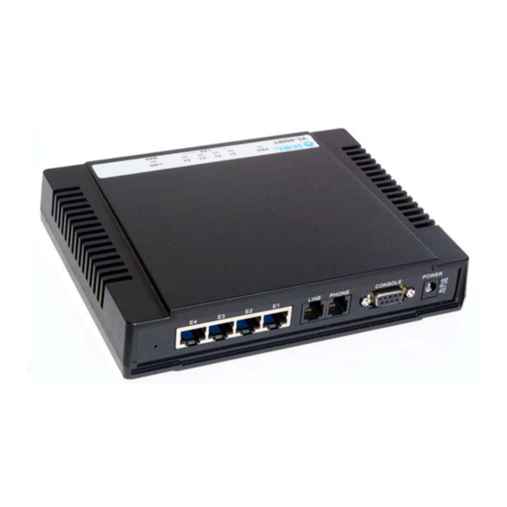
VC-400LT/RT+ VDSL2 CO&CPE Router MANUAL Ver.B3 Chapter 2. Hardware Description This section describes the important parts of the VC-400LT/R. It features the front indicators and rear connectors. VC-400LT Outward VC-400RT+ + Outward 2.1 Front Panel The following figure shows the front panel. Figure 3.1.1 VC-400LT / VC-400RT+ + front panel 2.2 Six LED indicators At a quick glance of the front panel, it will be easy to determine if the router has power... -
Page 10: Front Indicators
VC-400LT/RT+ VDSL2 CO&CPE Router MANUAL Ver.B3 2.3 Front Indicators The following table describes the LEDs. LEDs Color Status Descriptions On(Steady) The device is receiving the power and functioning properly. PWR(Power) Green The device is not ready or has malfunctioned. On(Steady) The device has a good Ethernet connection. E1~E4 The device is sending or receiving data or has Green... -
Page 11: Power On
VC-400LT/RT+ VDSL2 CO&CPE Router MANUAL Ver.B3 2.5 Power On 1. Check the adapter is properly connected. 2. Verify the power LED is steadily on. Chapter 3. Configure the VC-400LT/R Via Web Browser The VC-400LT/R provides a built-in HTML based management interface that allow user configure the VC-400LT/R via Internet Browser. -
Page 12: Select The Menu Level
VC-400LT/RT+ VDSL2 CO&CPE Router MANUAL Ver.B3 3.2 Select the Menu Level There is an easy Setup Wizard for end users at the VC-400RT+ and an Advanced Setup for more detail configurations. This manual attaches importance to the Advanced Setup. Figure 4.2 Select the Advanced Setup in the Entry Screen... -
Page 13: Select Advanced Setup
VC-400LT/RT+ VDSL2 CO&CPE Router MANUAL Ver.B3 3.3 Select Advanced Setup Select the Advanced Setup. The menu below will be used frequently. As an exercise and an example now the IP address will be set. Figure 4.3 Advanced Setup Note: The settings in the following Section 4.4 only need to be performed in order to change LAN settings. -
Page 14: Select Lan
VC-400LT/RT+ VDSL2 CO&CPE Router MANUAL Ver.B3 3.4 Select LAN The menu below will not be used very often, but when connecting the VC-400LT/R to a new control PC, one may want to go through the following steps in order to make the IP address previously set by ifconfig in the console or on some later occasion one may want to change it again without using the console then the menu below will be helpful. -
Page 15: Restart The Settings Dialog
VC-400LT/RT+ VDSL2 CO&CPE Router MANUAL Ver.B3 Figure 4.4.1 LAN Settings Now the IP address either may be changed or left as it is. If it has been changed in the form or after it has been changed through console ifconfig command, it needs to be “APPLY”... -
Page 16: Check Ip Via Cli Command
VC-400LT/RT+ VDSL2 CO&CPE Router MANUAL Ver.B3 Figure 5 Hyperterminal Configuration If the VDSL2 Router has been powered up already you will see a prompt by hitting the ENTER key. A screen is displayed as shown in Figure 5.2 Figure 5.2 Command Line Note: As you may identify from the commands above Industrial VDSL2 Router is a Linux based device. -
Page 17: Reset The System To Default Configuration
VC-400LT/RT+ VDSL2 CO&CPE Router MANUAL Ver.B3 Figure 5.3 ifconfig Note: You can use the serial Interface to configure an IP address by this command: ifconfig adm0 <ipadress> netmask <subnetmask> (Example: ifconfig adm0 192.168.16.217 netmask 255.255.255.0) This configuration is activated immediately but is only temporary because not stored in flash memory. -
Page 18: Chapter 5. Building A Vdsl2 System
VC-400LT/RT+ VDSL2 CO&CPE Router MANUAL Ver.B3 Chapter 5. Building a VDSL2 System First a quick overview on a complete setup of VC-400LT/R: Figure 6 VDSL2 Application 5.1 Connect the VC-400LT and the VC-400RT+ to the Line The objective for VDSL2 is to pass high speed data over a twisted pair cable. In the setup, connects VC-400LT to VC-400RT+ through phone wire or line simulator or any other hardware representation of a cable network, with or without noise injection... -
Page 19: Chapter 6. Operating The Vdsl2 System
VC-400LT/RT+ VDSL2 CO&CPE Router MANUAL Ver.B3 Chapter 6. Operating the VDSL2 System After the VDSL2 system has been set up, one may want to configure the settings that are related to VDSL2. Configuration of operation modes, test modes (loop back) and the display of status information are supported by GUI (Graphical User Interface). - Page 20 VC-400LT/RT+ VDSL2 CO&CPE Router MANUAL Ver.B3 Interleaving is a method of taking data packets, chopping them up into smaller bits and then rearranging them so that once contiguous data is now spaced further apart into a non continuous stream. Data packets are re-assembled by your router. The diagram below is an example of how interleaved traffic is transmitted.
-
Page 21: Line Configuration
VC-400LT/RT+ VDSL2 CO&CPE Router MANUAL Ver.B3 6.1.2 Line Configuration Figure 6.1.2 Line Configuration Menu for SNR Margin Selection Line Configuration Setting Description Direction Select the target direction. Set the required SNR Margin *10 Target SNRM (60=6dB) Note: Noise Margin is the non-technical term for Signal to Noise Ratio Margin (SNRM). Domestic standard modems and VDSL2 routers often use the terms Noise Margin or SNR when reporting on its value. - Page 22 VC-400LT/RT+ VDSL2 CO&CPE Router MANUAL Ver.B3 deployment with underlying POTS and ISDN services. Annex C allows VDSL2 ROUTER to coexist with TCM-ISDN services, found primarily in APAC. VC-400RT+whas numerous configuration profiles and bandplans to meet regional service provider requirements. The frequency bandwidth has increased to 30 MHz, with configuration options at 8.5 MHz, 12 MHz, 17.7 MHz and 30 MHz.
- Page 23 VC-400LT/RT+ VDSL2 CO&CPE Router MANUAL Ver.B3 Figure 6.1.3.2 VC-400RT+ Profile Configuration Note: Filter and Tone Mode of VDSL2 CO ROUTER and VDSL2 CPE ROUTER need to match. (Factory Default for Filter is Off, for Tone Mode is V43) Figure 6.1.3.3 Band Profile and Plan Setup Error Figure 6.1.3.4 Band Profile Region The following shows the band profile and band plan compatibility: Band Profile List...
- Page 24 VC-400LT/RT+ VDSL2 CO&CPE Router MANUAL Ver.B3 Band Profile \ Band Plan 10 11 13 14 16 18 20 21 22 23 24 25 26 O O O O O O O X X X X X X X X O O O O O O O X X X X X X X X X X O X X O X X X X X X X X X...
-
Page 25: Loop Back
VC-400LT/RT+ VDSL2 CO&CPE Router MANUAL Ver.B3 Note: The performance data above is for reference only, the actual data rate will vary on the quality of the copper wire and environment factors. 6.1.4 Loop Back Loopback (loop-back) describes ways of routing electronic signals, digital data streams, or flows of items from their originating facility back to the source without intentional processing or modification. -
Page 26: Line Activation
VC-400LT/RT+ VDSL2 CO&CPE Router MANUAL Ver.B3 test being done at one station and the two lines interconnected at the distant station. Commonly called loop around when the interconnecting circuit is accessed by dialing. A patch cable, applied manually or automatically, remotely or locally, that facilitates a loop-back test. - Page 27 VC-400LT/RT+ VDSL2 CO&CPE Router MANUAL Ver.B3 Figure 6.2.1 Line Status Display: Actual SNR Note: Band Actual SNR value, if the value is 0 dB, currently dose not transmit; if the value is negative, do not currently use. For example, the above screen display Band1 to Band3 value of 30A mode state.
- Page 28 VC-400LT/RT+ VDSL2 CO&CPE Router MANUAL Ver.B3 The following status messages may occur: Line Status Description Line Status Description EXCHANGE for VDSL2 this is Line Status is not not_initialized exchange a substate of FULL_INIT and is initialized! not reported. EXCEPTION SHOWTIME corresponds to corresponds to the exception showtime no sync...
-
Page 29: Channel Status
VC-400LT/RT+ VDSL2 CO&CPE Router MANUAL Ver.B3 INIT and is not reported. TRAINING for VDSL2 LOWPOWER L3 not supported Training this is a substate of FULL lowpower l3 by VDSL2. INIT and is not reported. ANALYSIS for VDSL2 All line states that are not analysis this is a substate of FULL unknown... -
Page 30: Version Info
VC-400LT/RT+ VDSL2 CO&CPE Router MANUAL Ver.B3 6.2.3 Version Info This function shows hardware and firmware version. Figure 6.2.3 Display of Version Data The firmware of web interface version: Web Interface Version. 6.2.4 SNR Graphs When VC-400LT link with VC-400RT+ , this graph will show the SNR value for each band. -
Page 31: Bitsgraphs
VC-400LT/RT+ VDSL2 CO&CPE Router MANUAL Ver.B3 Figure 6.2.4 Display of SNR per Carrier 6.2.5 BitsGraphs When VC-400LT link with VC-400RT+ , this graph will show the bits value for each tone. Figure 6.2.5 Display Bits Per Tone Graph Regarding the describe of "tone graph"(Only reference): "If slow service is indicated, technicians can look at the bits per tone measurement. -
Page 32: Chapter 7. Configuration Interface Of The Router
VC-400LT/RT+ VDSL2 CO&CPE Router MANUAL Ver.B3 wet sections on the span. Use a loop-troubleshooting tool with a TDR to find and fix these problems. If the bits per tone are low across the whole bandwidth, the cause is most likely DC troubles on the loop, such as shorts or grounds. -
Page 33: Setup Wizard And Advanced Setup
VC-400LT/RT+ VDSL2 CO&CPE Router MANUAL Ver.B3 7.2 Setup Wizard and Advanced Setup There is an easy Setup Wizard for end users at the VC-400RT+ Router only and an Advanced Setup for more detail configurations for both VC-400LT/R. This manual gives importance to the Advanced Setup. Figure 7.2 Select the Advanced Setup in the Entry Screen 7.2.1 Setup Wizard The Setup Wizard is designed for ease-of-use in order to quickly configure the most... -
Page 34: Advanced Setup
VC-400LT/RT+ VDSL2 CO&CPE Router MANUAL Ver.B3 7.2.2 Advanced Setup Click on the Advanced Setup link in the homepage in case you want to configure a wider range of settings. The following configuration options are displayed in the left navigation bar, as shown in Figure 7.2.2. ... -
Page 35: Administrator Settings
VC-400LT/RT+ VDSL2 CO&CPE Router MANUAL Ver.B3 Figure 7.2.3 System in the Left Navigator Bar 7.2.3.1 Administrator Settings To add a user or change user’s password, click on the “Administrator Settings” link in the left navigation bar. A screen is displayed as shown in Figure 7.2.3.1. Figure 7.2.3.1 Administrator Settings Configuration While adding a user, each user must assign a separate port. -
Page 36: Firmware Upgrade
VC-400LT/RT+ VDSL2 CO&CPE Router MANUAL Ver.B3 The screen contains the following details: Fields in User Setting: Field Description This is the password associated with the administrator. This is Current Password enabled only for the user Administrator login. Characters: 3-12. Password This is the password of the login administrator. -
Page 37: Device Mode
VC-400LT/RT+ VDSL2 CO&CPE Router MANUAL Ver.B3 The screen contains the following detail: Click "Browse" to select a specific file name in preparation upgrade the firmware. Click APPLY to start the firmware update. Notes: 1. If the machine firmware version is too old to be updated with the current firmware version of the gap, after the firmware upgrade must be reset system to default to avoid the new features can not use or system error. -
Page 38: Reboot
VC-400LT/RT+ VDSL2 CO&CPE Router MANUAL Ver.B3 Figure 7.2.3.4 Status Window 7.2.3.5 Reboot To reboot the unit, click on the “Reboot” link in the left navigation bar. A screen is displayed as shown in Figure 7.2.3.5. Figure 7.2.3.5 Reboot VC-400LT/R Router ... -
Page 39: Wan
VC-400LT/RT+ VDSL2 CO&CPE Router MANUAL Ver.B3 Figure 7.2.3.6 Reset VC-400LT/R Router Click Reset to restart the system to default configuration. After upgrade the firmware, and then automatically reboot. All settings will be cleard, and return to the default IP(192.168.16.249 / 192.168.16.250) 7.2.4 WAN The WAN settings can be viewed in the left navigation bar. -
Page 40: Dynamic Ip
VC-400LT/RT+ VDSL2 CO&CPE Router MANUAL Ver.B3 7.2.4.1 Dynamic IP To configure the WAN interface to dynamically obtain an IP Address, click on the “Dynamic IP” link in the left navigation bar. A screen is displayed as shown in Figure 7.2.4.1. Figure 7.2.4.1 Dynamic IP Configuration The screen contains the following details: ... - Page 41 VC-400LT/RT+ VDSL2 CO&CPE Router MANUAL Ver.B3 Figure 7.2.4.2 Static IP Configuration The screen contains the following details: Fields in Static IP: Field Description IP Address assigned by your Enter the IP Address of VC-400LT/R. Subnet Mask Enter the Subnet Mask of VC-400LT/R. ISP Gateway Address Enter the Gateway address of the VC-400LT/R.
-
Page 42: Pppoe
VC-400LT/RT+ VDSL2 CO&CPE Router MANUAL Ver.B3 7.2.4.3 PPPoE To configure the WAN interface to use PPPoE, click on the “PPPoE” link in the left navigation bar. A screen is displayed as shown in Figure 7.2.4.3. Figure 7.2.4.3 PPPoE Configuration The screen contains the following details: Fields in PPPoE: Field Description... -
Page 43: Dns
VC-400LT/RT+ VDSL2 CO&CPE Router MANUAL Ver.B3 Click APPLY to save the information that has been entered. Click CANCEL to exit from this page without saving the changes. 7.2.4.4 DNS To configure the DNS address, click on the “DNS” link in the left navigation bar. A screen is displayed as shown in Figure 7.2.4.4: Figure 7.2.4.4 DNS Configuration... -
Page 44: Lan
VC-400LT/RT+ VDSL2 CO&CPE Router MANUAL Ver.B3 7.2.5 LAN The LAN Setting can be viewed in the left navigation bar. The following are the options available under LAN, as shown in Figure 7.2.5: LAN Settings DHCP Client List LAN Switch Port Setting ... -
Page 45: Dhcp Client List
VC-400LT/RT+ VDSL2 CO&CPE Router MANUAL Ver.B3 Figure 7.2.5.1 LAN Settings The screen contains the following details: Fields in LAN Settings: Field Description IP Address Enter the LAN interface IP Address of VC-400LT/R. (Web IP) Subnet Mask Enter the LAN Subnet Mask of VC-400LT/R. Enable or disables the DHCP Server of the VC-400LT/R. -
Page 46: Lan Switch Port Setting
VC-400LT/RT+ VDSL2 CO&CPE Router MANUAL Ver.B3 7.2.5.3 LAN Switch Port Setting To view the All LAN Port Setting, click on the “Lan Switch Port Setting” link in the left navigation bar. A screen is displayed to all LAN Port Setting as shown in Figure 7.2.5.3. -
Page 47: Nat
VC-400LT/RT+ VDSL2 CO&CPE Router MANUAL Ver.B3 Input 1 Output 1 Input 2 Output 2 Input 3 Output 3 Input 4 Output 4 NWAY Force NWAY 10M Full 10M Half None Link Down 10M Half 10M Full 10M Full 10M Half Input 5 Output 5 Input 6... -
Page 48: Port Mapping
VC-400LT/RT+ VDSL2 CO&CPE Router MANUAL Ver.B3 The screen contains the following details: Fields in Virtual Server: Field Description Private IP Enter a private IP Address of specified entry. Private Port Enter a private Port number of the specified entry. Type Select virtual server protocol type of the specified entry. -
Page 49: Dmz
VC-400LT/RT+ VDSL2 CO&CPE Router MANUAL Ver.B3 The screen contains the following details: Fields in Port Mapping: Field Description Server IP Enter the IP Address of a specified local machine. Mapping Port Assign a range of port or specific port number to route the packets. Enabled Enable a specified entry of the Port Mapping. -
Page 50: Firewall Options
VC-400LT/RT+ VDSL2 CO&CPE Router MANUAL Ver.B3 Figure 7.2.7 Firewall in Left Navigator Bar 7.2.7.1 Firewall Options To enable the firewall options, click on the “Firewall Options” link in the left navigation bar. A screen is displayed as shown in Figure 7.2.7.1: Figure 7.2.7.1 Firewall Options Configuration The screen contains the following details: Fields in Firewall Options:... -
Page 51: Client Filtering
VC-400LT/RT+ VDSL2 CO&CPE Router MANUAL Ver.B3 7.2.7.2 Client Filtering Field Description Enable or disable the Client Filter feature of VDSL2 CO&CPE ROUTER. Enable Client Filter Select the check box to enable this option. Enter the filter IP Address range of the local machines under VDSL2 CO&CPE ROUTER. -
Page 52: Mac Control
VC-400LT/RT+ VDSL2 CO&CPE Router MANUAL Ver.B3 7.2.7.3 MAC Control To configure MAC Control, click on the “MAC Control” link in the left navigation bar. A screen is displayed as shown in Figure 7.2.7.3 Figure 7.2.7.3 MAC Control Configuration The screen contains the following details: Fields in MAC Control: Field Description... -
Page 53: Static Routing
VC-400LT/RT+ VDSL2 CO&CPE Router MANUAL Ver.B3 Figure 7.2.8 Route in Left Navigator Bar 7.2.8.1 Static Routing To setup Static Routing, click on the “Static Routing” link in the left navigation bar. A screen is displayed as shown in Figure 7.2.8.1. Figure 7.2.8.1 Static Routing Configuration... -
Page 54: Routing Table List
VC-400LT/RT+ VDSL2 CO&CPE Router MANUAL Ver.B3 The screen contains the following details: Fields in Static Routing: Field Description Destination LAN IP Enter the IP Address 0-0-0-0 of routing entry. Subnet Mask Enter the Subnet Mask 0-0-0-0 of routing entry. Gateway Enter the Gateway address of routing entry. -
Page 55: Settings
VC-400LT/RT+ VDSL2 CO&CPE Router MANUAL Ver.B3 Figure 7.2.9 UPnP in Left Navigator Bar 7.2.9.1 Settings To enable or disable the UPnP Settings, click on the “Settings” link in the left navigation bar. A screen is displayed as shown in Figure 8.2.9.1. Figure 7.2.9.1 UPnP Configuration The screen contains the following details: Fields in UPnP Settings:... -
Page 56: Appendix A: Product Features & Specification
VC-400LT/RT+ VDSL2 CO&CPE Router MANUAL Ver.B3 Appendix A: Product Features & Specification Features: Compliant with IEEE 802.3 & 802.3u Ethernet Standards Compliant with G993.2 VDSL2 standards Provides 4 x 10/100M auto-sensing RJ-45 Ethernet ports Supports Bandwidth up to 100Mbps over RJ-11 ports ... -
Page 57: Specifications
VC-400LT/RT+ VDSL2 CO&CPE Router MANUAL Ver.B3 Specifications: Standard: IEEE802.3 standard IEEE802.3u standard Compliant G993.2 VDSL2 standard Interface: 4 * RJ-45 10/100Mbps Ethernet port 1 * RJ-11 connector for VDSL2 1 * RJ-11 connector for POTS/ISDN device Band Profile: 8a, 8b, 8c, 8d, 12a, 12b, 17a, 17b, 30a Band Plan: 997, 998 Max. -
Page 58: Appendix B: Troubleshooting
VC-400LT/RT+ VDSL2 CO&CPE Router MANUAL Ver.B3 Appendix B: Troubleshooting Connected the CO Router with CPE Router within 300 meters RJ-11 phone 1. Symptom: cable got only less than 10 Mbit/s. Some testing program which is base on TCP/IP protocol such as FTP, Iperf, Cause: NetIQ, the bandwidth of testing outcome will be limited by TCP window size. -
Page 59: Appendix C: Cable Requirements
VC-400LT/RT+ VDSL2 CO&CPE Router MANUAL Ver.B3 Appendix C: Cable Requirements A CAT 3, 4 or 5 UTP (unshielded twisted pair) cable is typically used to connect the Ethernet device to the modem. A 10Base-T cable often consists of four pairs of wires, two of which are used for transmission. - Page 60 VC-400LT/RT+ VDSL2 CO&CPE Router MANUAL Ver.B3 Figure C-3 Pin Assignments and Wiring for an RJ-45 Crossover Cable Serial Console Interface Connector Pin Assignments The serial console interface connector is a 9-pin, RS-232 D-type, DTE connector. A null modem cable is required to connect a workstation running the Linux or Windows operating system. Table C-2 lists the pin assignments for the serial console interface connector.
-
Page 61: Appendix D : Compliance And Safety Information
VC-400LT/RT+ VDSL2 CO&CPE Router MANUAL Ver.B3 Appendix D : Compliance and Safety Information FCC Radio Frequency Interference Statement This equipment has been tested to comply with the limits for a computing device, pursuant to Part 15 of FCC rules. These limits are designed to provide reasonable protection against harmful interference when the equipment is operated in a commercial environment. - Page 62 VC-400LT/RT+ VDSL2 CO&CPE Router MANUAL Ver.B3 Avoid using a telephone during an electrical storm. There may be a remote risk of electrical shock from lightning. Do not use the telephone to report a gas leak in the vicinity of the leaking area. ...
-
Page 63: Warranty
VC-400LT/RT+ VDSL2 CO&CPE Router MANUAL Ver.B3 Warranty The original owner of this package will be free from defects in material and workmanship for one year parts after purchase. For the warranty to apply, you must register your purchase by returning the registration card indicating the date of purchase.
Need help?
Do you have a question about the VC-450RT and is the answer not in the manual?
Questions and answers