Welch Allyn 5102 Service Manual

Welch Allyn 5102 Service Manual

Non-masted scales

Advertisement

Welch Allyn Non-Masted Scales
Service Manual
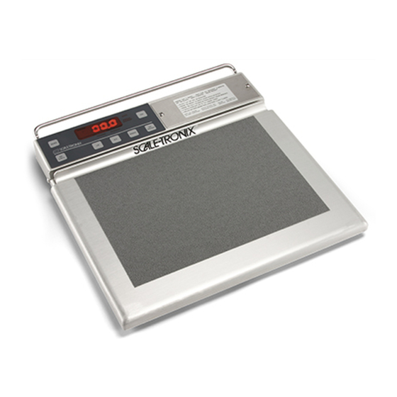
Model 5102 Physician's Stand-On Scale
Model 5125 Portable Stand-On Scale
Model 5127 Bariatric Portable Stand-On Scale

Advertisement

Table of Contents
loading

Summary of Contents for Welch Allyn 5102

  • Page 1 Welch Allyn Non-Masted Scales Service Manual Model 5102 Physician’s Stand-On Scale Model 5125 Portable Stand-On Scale Model 5127 Bariatric Portable Stand-On Scale...
  • Page 2 © 2016 Welch Allyn. All rights are reserved. To support the intended use of the product described in this publication, the purchaser of the product is permitted to copy this publication, for internal distribution only, from the media provided by Welch Allyn. No other use, reproduction, or distribution of this publication, or any part of it, is permitted without written permission from Welch Allyn.
  • Page 3: Table Of Contents

    Specified Torque Values .......................... 17 5125 & 5127 Disassembly ........................18 5102 Disassembly............................ 27 Repair Parts List ............................34 5125 & 5127 Repair Parts List ......................... 34 5102 Repair Parts List ..........................35 Schematics ..............................36 5125/5127 Schematics ..........................36 5102 Schematics ............................. 41...
  • Page 4: Custom Setup

    Custom setup You can customize the scale to best suit your needs. Configurations that can be selected include the automatic shut-off time, weighing units (if available), weight resolution, and more. Enter custom setup mode 1. Make sure the scale is powered down. 2.
  • Page 5 RECALL rECALL* This option allows you to turn button functionality. rS-232 Detailed instructions for this feature are available from Welch Allyn. Go to http://www.welchallyn.com/en/other/contact-us.html to find your local representative. OutPut* This option displays the current data port output option. Detailed instructions for this feature are available from Welch Allyn.
  • Page 6 rts.cts* This option allows you to turn the handshaking hardware for serial transmissions. PRINT Prtbtn* This option allows you to turn the front panel button. rtEPrt* This option allows you to turn the enabling of printing from a remote location by connecting the receive line to the ground.
  • Page 7: Enter Advanced Service Mode

    Enter Advanced Service Mode 1. To enter the "service" mode start with the scale turned off. 2. Note the small "ST" logo ("ST") located directly above the "RE CALL" pushbutton, and below the “ZERO” pushbutton on the front panel of the readout. 3.
  • Page 8: Support Services

    Warranty Welch Allyn will warranty the weight scale to be free of defects in material and workmanship and to perform in accordance with manufacturer specifications for the period of one year from the date of retail purchase. The warranty period shall start on the date of purchase. The date of purchase is: 1) the invoiced ship date if the...
  • Page 9: Returning Products

    To ensure safe receipt of your device by the service center and to expedite processing and return of the device to you, thoroughly clean all residues from the device before you ship it to Welch Allyn. For cleaning requirements, see the Cleaning instruction in the Directions for Use.
  • Page 10: Non-Warranty Service

    CAUTION Use only size C disposable alkaline batteries. The use of any other battery will void the warranty. 1. Using a screwdriver, remove the two battery access door screws located on the right of the display (5102 is below display) and remove the door.
  • Page 11: Calibration Procedure

    TEST CALIBRATION WEIGHTS ARE AVAILABLE FROM WELCH ALLYN. THREE (3) 25 KILOGRAM TEST WEIGHTS ARE RECOMMENDED. ORDER PART NO. 20021W. (25 KG TEST WEIGHTS) Large changes in calibration often indicate a damaged load cell or faulty readout component. It is generally recommended that if calibration is necessary for your scale it should be returned to the factory.
  • Page 12: Troubleshooting Of Scale

    DATA OUTPUT (RS232) DETAILS For detailed help and information regarding the data output capabilities, contact Welch Allyn. RS232 data output has been made a standard feature on many of our scales in 2013. Existing scales can be easily modified to provide data output when needed.
  • Page 13 WHT(3) TO RED(4) 325-375Ω Consult Welch Allyn if readings differ from those shown. NOTE: Ohmmeters will not indicate a change in resistance of the load cell transducer when weights are applied to scale. This is due to the extremely small change in resistance of the strain gauges employed (<1 ohm) and the fact that the bridge configuration presents a constant value of resistance when measured from its terminals.
  • Page 14: Symptom And Solutions

    Symptom and Solutions Possible Symptom Corrective Action Cause Scale does not Dead Batteries or Replace Batteries (Alkaline “C” Cells) turn on no rear Adapter Faceplate Remove Front Panel. Check to make sure the Black and Red cable connector is in place. Replace the switch assembly or Cracked Battery the Battery Holder Assembly.
  • Page 15 Symptom Possible Corrective Action Cause Numbers are not Remove the Display Board (see directions above) lighting up 1. Gently, lift a working 7 Segment LED chip with a flat (Missing head screw driver and exchange with a non- Segments of the working LED chip.
  • Page 16 Symptom Possible Corrective Action Cause Weight Remains Memory Chip or U9 and EM1033 or Microprocessor – Replace the Main Microprocessor Board the same Any other Error Main board, Repair, replace as needed Modes Display Board, Load Cell...
  • Page 17: Disassembly Guide

    Disassembly Guide Required Tools: 7/16” socket 1/8” Allen wrench 11 mm socket 5/32” Allen wrench Ratchet socket driver 3/8” wrench #1 Phillips screwdriver 7/16” wrench Slotted screwdriver 3/8” socket 1/8” slotted screwdriver Specified Torque Values Screw Installation Material Torque Specification Bit Type Description ¼-20 x 1/2 BHSC...
  • Page 18: 5125 & 5127 Disassembly

    5125 & 5127 Disassembly Note: Reassembly is reverse of Dis-Assembly Note: Whenever the scale is opened for repair purposes a Calibration must be performed. 1. Make sure that the scale is powered down by observing the readout screen. If the screen is empty, it is off.
  • Page 19 4. Use a 11 mm socket to remove the four corner nuts. 5. Flip the scale back and pull the slider deck away from the main body to access the inside of the scale. 6. Use a 1/8” Allen wrench to unscrew the two screws on the side of the readout cover.
  • Page 20 8. Use a #1 Phillips screwdriver to unscrew and remove the four screws from the circuit board. 9. Unplug the white connector with two black wires and one red wire from the circuit board. 10. Remove the blue ribbon cable and black ribbon cable from the readout circuit board.
  • Page 21 11. Remove the circuit board from the scale body. 12. Use a 7/16” wrench to remove the two nuts on the back of the handle screws. 13. Use a 5/32” Allen wrench to remove the two screws on each side of the handle.
  • Page 22 14. Remove the handle to access the main body of the scale. 15. Use a #1 Phillips screwdriver to unscrew and remove the four screws from the battery holder.
  • Page 23 16. On the instrument board, unplug the J1 power connector. 17. Unplug the J14 RS 232 connector. 18. Unplug the J4 load cell connector.
  • Page 24 19. Using a #1 Phillips screwdriver, unscrew and remove the four corner screws on the instrument board and remove the main circuit board. 20. Unplug the clear connector from the junction board by pulling it off from the white port.
  • Page 25 21. Unplug the black connectors from the junction board by pressing the black switch on the connectors and slowly pull it out from the port. 22. Using a #1 Phillips screwdriver, unscrew and remove the two screws on the upper left and lower right corner of the junction board.
  • Page 26 25. Remove the load cells from the load beam spacer. 26. Using a 3/8” wrench, unscrew and remove the two nuts from the load beam spacer.
  • Page 27: 5102 Disassembly

    5102 Disassembly Note: Reassembly is reverse of Disassembly Note: Whenever the scale is opened for repair purposes a Calibration must be performed. 1. On the wall mount readout, use a #1 Phillips screwdriver to remove the two screws of the battery panel cover 2.
  • Page 28 5. Pull the readout cover panel from the readout 6. Unplug the J14 RS 232 connector 7. Unplug the J4 load cell connector...
  • Page 29 8. Unplug the J1 power connector 9. Unplug the J6 display connector 10. Using a #1 Phillips screwdriver, remove the screw on each corner and remove the board...
  • Page 30 11. Observe the readout circuit board 12. Using a #1 Phillips screwdriver, remove the screw on each corner of the board 13. Unplug the blue ribbon cable from the port 14. Remove the 4 Safety Walk Tape, 2” x 3” in size.
  • Page 31 15. Remove the 4 Jam Nuts (1/4-20; 131052) using a 7/16” deep socket and ratchet socket driver to separate the top and bottom platforms. 16. Remove slider 17. Using a 5/32” Allen wrench, remove each load cell’s four screws...
  • Page 32 18. Remove the 2 Load Cell Spacers (133089) from Bottom Platform with 4 Screws (10-32 x ¾ FH; 40523) and 4 Lock Nuts (10-32 KEPS) using a 3/8“deep socket and ratchet socket driver. 19. On the junction board, unplug the clear connector and remove the black connector by gently pressing the black switch on the connector...
  • Page 33 20. Using a #1 Phillips screwdriver, remove the junction board’s two screws, remove the junction board 21. Remove 2 Screws (4-40 x ½ FH PHIL; 66530) and 2 Lock Nuts (4-40 KEPS) using #1 Phillips screw driver. Position Shell so set screw hole faces access hole.
  • Page 34: Repair Parts List

    531014 SHUR STEP GRAY - 10" X 14" - 5125 531016 SHUR-STEP GRAY 2" X 3" 133096 Load Mounts 3/8” 255019-KIT CALIBRATION PLUG, 5102, 5125 705057 ALKALINE "C" CELLS 450006-KIT FIRMWARE 5002 V2.13.5 630035 BATTERY HOLDER W/EXTERNAL JACK ASSY 700116 PCB INSTRUMENT BOARD (No Cal &...
  • Page 35: 5102 Repair Parts List

    READOUT ASSEMBLY 133086 LOADMOUNT 3/8" X 1" WITH 3/8" 400038 LOAD BEAM 75KG THRU HOLE 11" 531008 SHUR STEP GRAY 12" X 16" 5102 531016 SHUR-STEP GRAY 2" X 3" 700119W JUNCTION Bd 5202 6202 VG 710047W HARNESS, INTERIOR PLATFORM L/C...
  • Page 36: Schematics

    Schematics 5125/5127 Schematics...
  • Page 41: 5102 Schematics

    5102 Schematics...

This manual is also suitable for:

51255127

Table of Contents