
Related Manuals for ROSSO MOTORS Kids ATV


Summary of Contents for ROSSO MOTORS Kids ATV
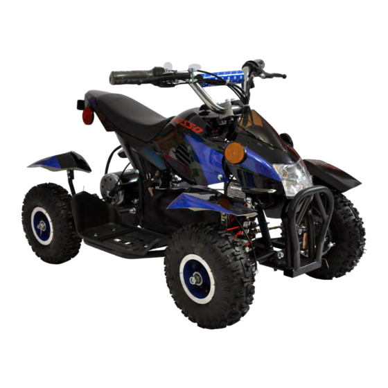
- Page 1 ROSSO MOTORS ELECTRIC ATV OWNERS MANUAL Read and understand this manual Prior to Riding! DO NOT RETURN TO STORE! Illustrations may not be exact appearance of actual product.
-
Page 2: Table Of Contents
Table of Contents General information: ..............................3 Assembly: .................................5 Components definition: ............................11 Maintenance and adjustments ...........................14 Troubleshooting ..............................16 Wiring diagram: ..............................17 Warranty ................................18... -
Page 3: General Information
Your kids ATV is meant to be used on private property and on closed courses and not on public streets or sidewalks , unless approved by your local traffic laws. Do not ride your electric ATV in any areas where pedestrians or vehicle traffic is present. - Page 4 Never hitch on to another product. Do not ride the Rosso Motors on wet or icy weather and never immerse the electric ATV in water, as the electrical and drive components could be damaged by water or create other possible unsafe conditions.
-
Page 5: Assembly
Assembly: • Rosso Motor’s electric ATV requires minimum assembly. • Please follow instructions below in order to get your electric ATV assembled properly. • The Rosso Motor’s ATV comes in 2 boxes, one contains the ATV and hardware and the other one contains battery. - Page 6 3.Handlebar installation: Failure to properly adjust and tighten the bolts can result in a loss of control of your ATV. Attach handlebar clamps and gear position indicator Handlebar clamp bolts Gear position indicator Handlebar clamp 4. Front wheels installation (repeat steps below for right and left wheels) Remove self-locking nut and Insert front wheel into the axle and tighten the Front axle Nylon nut...
- Page 7 6.Front brake calipers installation (repeat steps below for right and left wheels) Step 1: Insert brake caliper and make sure the disc brake is located in between the brake pads: Disc brake Brake pads Step 2: Attach caliper to the mount using brake caliper mounting bolts and tighten them Step 3: Adjust caliper by tighten or untighten caliper alignment bolts –...
- Page 8 7.Rear shock absorber installation Step 1: Raise rear end of the ATV Step 2: Install shock absorber into the bottom mount and tighten the bolt Shock absorber Connector plug 8.Battery installation Step 1: Open battery bag and pull out connector plug Step 2: Remove battery security plate and place battery into the casing Casing...
- Page 9 Step 3: Connect plugs - insert the wire until you hear “CLICK” Step 4: Close battery bag, secure security plate and tighten the bolts...
- Page 10 9. THIS SECTION LEFT EMPTY INTENTIONALLY 10.Install reflectors (RED reflectors at the back of the ATV and ORANGE at the front) Rear Left & Right Front Left & Right Rear Center...
-
Page 11: Components Definition
Components definition: Seat Rear brake lever Front brake lever Head lights V.1` Motor Controller Operation controls: 1. Gear shifter switch Head lights V.2` 2. Gear position indicator When gear shifter is in N (neutral) position – (green light) is on When gear shifter is in R (reverse) position –... - Page 12 3.Ignition/Power switch 4.Battery level indicator Located on the right side of the handle bar, MAX (green) – battery capacity is full MID (yellow) – battery capacity is half full MIN (red) – battery capacity is battery needs to be charged 5.Headlight switch Located on the left side of the handle bar I –...
- Page 13 6.Parking brake Located on the right side brake lever To engage: squeeze front brake lever and press the brake knob To disengage: squeeze brake lever until the know pops up 7.Fuse Located at the front left side of the ATV Fuse specs: 250V-30A FUSE 8.Speed switch...
-
Page 14: Maintenance And Adjustments
Maintenance and adjustments MAKE SURE THE INGITION (MAIN SWITCH) IS OFF BEFORE PERFORMING ANY MAINTANANCE OR ADJUSTMENTS 1.Brakes adjustment Failure to inspect and properly adjust brakes increases the risk accidents. Riding with worn brake pads can reduce braking performance and cause an accident. Check and adjust brakes before each ride To adjust cable play on the left (rear) brake lever –... - Page 15 2.Charging Charge batteries for at least 12 hours before initial use! Charger might get warm during charging process; this situation is normal and notconcerning. If the charger does not get warm, it does not mean that it is not workingproperly. Step 1: Turn main switch OFF Step 2: Plug the charger into the charging port (located underneath the fuse) Step 3: Plug charger into a wall –...
-
Page 16: Troubleshooting
Step 2: Adjust (tight/untighten) chain adjuster bolts as necessary – make sure both bolts are adjusted equally Step 3: Tighten mount nuts... -
Page 17: Wiring Diagram
Wiring diagram:... -
Page 18: Warranty
Warranty ROSSO warranties this product to be free of manufacturing defects for a period of 90 days from MOTORS date of purchase. This Limited Warranty does not cover normal wear and tear, tires, tubes or cables, or any damage, failure or loss caused by improper assembly, maintenance, or storage or use MANTERAY This Limited Warranty is voided if the product is: •...
Need help?
Do you have a question about the Kids ATV and is the answer not in the manual?
Questions and answers