Table of Contents
Advertisement
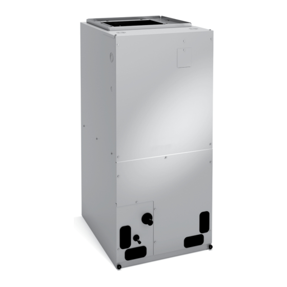
BCE3M*C & BCS3M*C SERIES AIR HANDLER
These instructions must be read and understood completely before attempting installation.
This is a safety alert symbol and should never be ignored. When you see this symbol on labels or in
manuals, be alert to the potential for personal injury or death.
THIS MANUAL MUST BE LEFT WITH THE
HOMEOWNER FOR FUTURE REFERENCE
Improper installation, adjustment, alteration, service
or maintenance can cause property damage, personal
injury or loss of life. Installation and service must be
performed by a licensed professional installer (or
equivalent), service agency or the gas supplier.
215 Metropolitan Drive
West Columbia, SC 29170
507621-01
INSTALLATION INSTRUCTIONS
WARNING
Table of Contents
Unit Dimensions ..........................................................2
Shipping and Packing List ...........................................3
General ........................................................................3
Requirements ..............................................................3
Installation Clearances ................................................4
Installation ...................................................................4
Condensate Drain........................................................8
Duct System and Filters ............................................10
Brazing Refrigerant Lines ..........................................11
Sealing the Unit .........................................................13
Electrical Connections ...............................................13
Air Flow - Cooling Blower Speed ............................17
Check-Out Procedures ..............................................19
Operation ...................................................................19
Maintenance ..............................................................20
Cabinet Insulation ......................................................20
Use of Air Handler During Construction.....................21
This product contains a chemical known to the State
of California to cause cancer, birth defects or other
reproductive harm.
The Clean Air Act of 1990 bans the intentional venting
of refrigerant (CFCs, HCFCs and HFCs) as of July
1, 1992. Approved methods of recovery, recycling or
reclaiming must be followed. Fines and/or incarceration
may be levied for noncompliance.
*P507621-01*
Issue 1720
WARNING
CAUTION
(P) 507621-01
Page 1 of 23
Advertisement
Table of Contents

Related Manuals for Lennox BCE3M*C SERIES


Summary of Contents for Lennox BCE3M*C SERIES
-
Page 1: Table Of Contents
INSTALLATION INSTRUCTIONS BCE3M*C & BCS3M*C SERIES AIR HANDLER These instructions must be read and understood completely before attempting installation. This is a safety alert symbol and should never be ignored. When you see this symbol on labels or in manuals, be alert to the potential for personal injury or death. Table of Contents Unit Dimensions ............2 Shipping and Packing List ...........3... -
Page 2: Unit Dimensions
Unit Dimensions 1 (25) SUPPLY AIR OPENING 1 (25) 1 (25) LOW VOLTAGE INLETS (Top and Right Side) LINE VOLTAGE INLETS (Top and Left Side) TOP VIEW 3/4 (19) LINE VOLTAGE INLETS (Top and Right Side) CIRCUIT LOW VOLTAGE INLETS BREAKER (Either Side) COVER... -
Page 3: Shipping And Packing List
NOTE: These instructions are intended as a general guide and do not supersede national, state or local codes in any way. CAUTION Physical contact with metal edges and corners while Shipping and Packing List applying excessive force or rapid motion can result in personal injury. -
Page 4: Installation Clearances
Installation Clearances WARNING Danger of explosion. Keep flammable Non-Ducted Return Closet Installation materials and vapors, such as gasoline, away The air handler can be installed in a closet with a false from air handler. Place air handler so that bottom to form a return air plenum. It may also be installed heating elements are at least 18 inches (46 with a return air plenum under the air handler. - Page 5 NOTE: When the unit is installed in horizontal applications, For all performance testing, units must be tested in the upflow orientation with the horizontal drain pan removed. a secondary drain pan is recommended. Refer to local codes. Refrigerant Metering Device NOTE: This unit may be installed in left-hand or right-hand These units are equipped with a factory-installed metering air discharge horizontal applications.
- Page 6 Right-Hand Air Discharge For horizontal right-hand air discharge, the following field modifications are required. 1. Remove and set aside blower and coil access panels. Remove brackets securing pan to unit. See figure 4. Figure 5 Figure 4 Remove coil assembly, bottom drain pan and horizontal drain pan as one unit from the air handler.
-
Page 7: Cover The Hairpins. See Figure
Reinstall the top cap. Rotate the blow-off prevention Reinstall the brackets that hold the coil and horizontal brackets 180º and reinstall using the same screws. drain pan in place. See figure 9. Use the correct mounting holes; the brackets must cover the hairpins. -
Page 8: Condensate Drain
Condensate Drain The air handler is provided with ¾” NPT condensate drain connections. IMPORTANT On units of this type, where the blower “draws” rather than “blows” air through the coil, traps must be installed in the condensate drain lines (primary and auxiliary, if used). Traps prevent the blower from drawing air through the drain lines into the air supply. -
Page 9: Figure
Sloping the Unit NOTE: When installing drain line connection fittings to the drain pan, hand tighten the fitting and use a Make sure the unit is sloped (similar to the slope shown in thread sealant. Over-tightening the fittings can split figure 11) (horizontal or upflow) so that the drain pan will connections on the drain pan. -
Page 10: Duct System And Filters
Installing Duct System Duct System and Filters Install the conditioned air plenum, ducts and air filters (not provided) in accordance with NFPA 90B Standard for Duct System the Installation of Warm Air Heating and Air-Conditioning The air handler is provided with flanges for the connection Systems (latest edition). -
Page 11: Brazing Refrigerant Lines
Brazing Refrigerant Lines CAUTION Refrigerant lines must be connected by a qualified Brazing alloys and flux contain materials which are technician in accordance with established procedures. hazardous to your health. Avoid breathing vapors or fumes from brazing IMPORTANT operations. Perform operations only in well ventilated areas. - Page 12 PLEASE READ IMPORTANT ISSUES CONCERNING BRAZING OPERATIONS ON PREVIOUS PAGES BEFORE PROCEEDING. NOTE - REFER TO OUTDOOR UNIT INSTALLATION INSTRUCTIONS FOR REFRIGERANT PIPING SIZE REQUIREMENTS. NOTE - Use silver alloy brazing rods with five or six percent minimum silver alloy for copper-to-copper brazing, 45 percent alloy for copper-to-brass and copper-to-steel brazing.
-
Page 13: Sealing The Unit
Sealing the Unit WARNING Seal the unit so that warm air is not allowed into the cabinet. Run 24V Class II wiring only through specified low Warm air introduces moisture, which results in water blow- voltage opening. Run line voltage wiring only through off problems. - Page 14 • The power supply must be sized and protected according to the specifications supplied on the product. • This air handler is factory-configured for 240 volt, single phase, 60 cycles. For 208-volt applications, see “208 Volt Conversion” later in this section. •...
- Page 15 PART NO. 067203400 WIRING DIAGRAM - ELECTRIC HEAT HEATERS USED 2nd STAGE 5 KW = HE1 SEQUENCER 2 18 BLK CIRCUIT BREAKER 2 7.5 & 10 KW = HE1 & HE2 12 BLK 15 KW = HE1,HE2 & HE3 12 BLK 12 BLK 20 KW = HE1,HE2,HE3 &...
- Page 16 THERMOSTAT AIR HANDLER THERMOSTAT AIR HANDLER NOTE NOTE HEAT ONLY APPLICATION CONDITIONER THERMOSTAT HEAT PUMP UNIT UNIT AIR HANDLER COOLING ONLY APPLICATION THERMOSTAT AIR HANDLER CONNECT COMMON WIRE ONLY IF REQUIRED (REFER TO THE APPROPRIATE THERMOSTAT INSTALLATION INSTRUCTIONS) NOTE HEAT PUMP APPLICATION WITH AIR CONDITIONER ELECTRIC HEAT UNIT...
-
Page 17: Air Flow - Cooling Blower Speed
Change Blower Speed Air Flow — Cooling Blower Speed Disconnect all power supplies. Remove the air handler access panel. The cooling blower speed is factory configured to provide Locate pin number 2 on the blower relay. Two black correct air flow for an outdoor unit that matches the cooling wires are connected to this terminal pin. - Page 18 Air Handler Blower Speed .10” WC .20” WC .30” WC .40” WC .50” WC Model Low (Red) -018 Med (Blue) High (Black) Low (Red) -024 Med (Blue) High (Black) 1130 1100 1070 1010 Low (Red) -030 Med (Blue) 1075 1060 1030 High (Black) 1240...
-
Page 19: Check-Out Procedures
Check Electric Heater (if used) Check-Out Procedures • Set thermostat to call for auxiliary heat (approximately 5°F above ambient temperature). The indoor blower and auxiliary heat should come on together. Allow a NOTE: Refer to outdoor unit installation instructions for minimum of 3 minutes for all sequencers to cycle on. -
Page 20: Maintenance
Heating (Heat Pump) Cabinet Insulation When the thermostat calls for heating, 24 volts is applied to the blower time-delay relay coil. The normally open contacts close, causing the indoor blower motor to operate. The IMPORTANT circuit between R and Y is completed, closing the circuit to the contactor in the outdoor unit, starting the compressor DAMAGED INSULATION MUST BE REPAIRED and outdoor fan motor. -
Page 21: Use Of Air Handler During Construction
Use of Air Handler During Construction Allied Air does not recommend the use of its air handler unit during any phase of construction. Very low return air temperatures, harmful vapors and operation of the unit with clogged or misplaced filters will damage the unit. Air handler units may be used for heating (heat pumps) or cooling of buildings under construction, if the following conditions are met:... - Page 22 Installing Contractor’s Name_______________________ Installing Date_______________________________ Installing Contractor’s Phone_______________________ Air Handler Model #___________________________ Job Address____________________________________ Thermostat Line Voltage SUPPLY Disconnect Switch Integrated Control Temperature Duct Blower Motor Amps System Electric Heat Amps Duct Static RETURN Filter Drain Line DUCT SYSTEM TOTAL EXTERNAL STATIC (dry coil) dry coil wet coil SUPPLY AIR DUCT...
- Page 23 Installing Contractor’s Name_______________________ Installing Date_______________________________ Installing Contractor’s Phone_______________________ Air Handler Model #___________________________ Job Address____________________________________ Line Voltage Disconnect Switch Thermostat Integrated Control Duct System Duct System Filter RETURN SUPPLY Electric Heat Amps Blower motor Amps Drain Line Duct Static Temperature DUCT SYSTEM TOTAL EXTERNAL STATIC (dry coil) dry coil wet coil...
Need help?
Do you have a question about the BCE3M*C SERIES and is the answer not in the manual?
Questions and answers