Advertisement
Service Literature
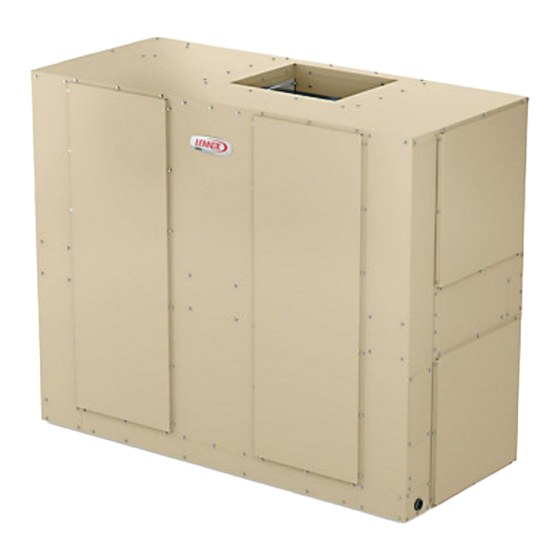
Lennox ELA model blower−coil units are designed for
upflow or horizontal air and indoor applications only.
ELA blower units are available in six models; 072, 090,
120, 150, 180 and 240. The units match up with Lennox
ELS condensing units and Lennox ELP heat pump units
charged with HFC−410A refrigerant.
Information and specifications contained in this manual
are subject to change. Procedures outlined in this manual
are presented as a recommendation only and do not su-
persede or replace local or state codes.
WARNING
Improper installation, adjustment, alteration, service
or maintenance can cause property damage, personal
injury or loss of life. Installation and service must be
performed by a licensed professional HVAC installer or
equivalent, service agency, or the gas supplier.
IMPORTANT
The Clean Air Act of 1990 bans the intentional venting of
refrigerant (CFCs, HCFCs and HFCs) as of July 1, 1992.
Approved methods of recovery, recycling or reclaiming
must be followed. Fines and/or incarceration may be
levied for noncompliance.
WARNING
Electric shock hazard! - Disconnect all power
supplies before servicing.
Replace all parts and panels before
operating.
Failure to do so can result in death or
electrical shock.
CAUTION
As with any mechanical equipment, contact with sharp
sheet metal edges can result in personal injury. Take
care while handling this equipment and wear gloves and
protective clothing.
UNIT INFORMATION
Corp. 1810-L3
February 15, 2019
ELA SERIES AIR HANDLER UNITS
Page 1
Table of Contents
SPECIFICATIONS ..........................................................2
BLOWER DATA ..............................................................4
I - UNIT COMPONENTS ..............................................19
II − REFRIGERATION SYSTEM ..................................20
III − BLOWER SPEED & BELT TENSION ....................20
IV − Electric Heat Components ....................................21
ELA Supply Air Inverter Startup ....................................22
Verify Proper Operation ................................................23
V - Wiring Diagrams .....................................................24
ELA
6 - 20 TONS
Advertisement
Table of Contents

Related Manuals for Lennox ELA Series


Summary of Contents for Lennox ELA Series
-
Page 1: Table Of Contents
ELA blower units are available in six models; 072, 090, 120, 150, 180 and 240. The units match up with Lennox ELS condensing units and Lennox ELP heat pump units charged with HFC−410A refrigerant. -
Page 2: Specifications
SPECIFICATIONS General Model No. ELA072S4S ELA090S4D Data Nominal Tonnage Blower Type MSAV (Multi-Stage Air Volume) MSAV (Multi-Stage Air Volume) ® ® Connections No. of Circuits Liquid line o.d. - in. (sweat) (1) 5/8 (2) 5/8 Suction/Vapor line o.d. - in. (sweat) (1) 7/8 (2) 7/8 Condensate drain - in. - Page 3 OPTIONS / ACCESSORIES Item Catalog ELECTRIC HEAT 10 kW 208/240V-3ph - T3EH0010LM1Y 46W50 460V-3ph - T3EH0010LM1G 46W55 46W60 575V-3ph - T3EH0010LM1J 15 kW 208/240V- 3ph - T3EH0015LM1Y 46W51 460V-3ph - T3EH0015LM1G 46W56 575V-3ph - T3EH0015LM1J 46W61 25 kW 208/240V-3ph - T3EH0025LM1Y 46W52 460V-3ph - T3EH0025LM1G 46W57...
-
Page 4: Blower Data
BLOWER DATA ELA072 BLOWER PERFORMANCE FOR ALL UNITS ADD: 1 - Wet indoor coil air resistance of selected unit. pages 11 and 12. Then determine from table the blower motor hp and drive rpm required. See page 10 STATIC PRESSURE EXTERNAL TO UNIT - Inches Water Gauge Volume RPM BHP RPM BHP RPM BHP RPM BHP RPM BHP RPM BHP RPM BHP RPM BHP RPM BHP 1200... - Page 5 BLOWER DATA ELA090 BLOWER PERFORMANCE FOR ALL UNITS ADD: 1 - Wet indoor coil air resistance of selected unit. pages 11 and 12. Then determine from table the blower motor hp and drive rpm required. See page 10 STATIC PRESSURE EXTERNAL TO UNIT - Inches Water Gauge Volume RPM BHP RPM BHP RPM BHP RPM BHP RPM BHP RPM BHP RPM BHP RPM BHP RPM BHP 1600...
- Page 6 BLOWER DATA ELA120 BLOWER PERFORMANCE FOR ALL UNITS ADD: 1 - Wet indoor coil air resistance of selected unit. pages 11 and 12. Then determine from table the blower motor hp and drive rpm required. See page 10 STATIC PRESSURE EXTERNAL TO UNIT - Inches Water Gauge Volume RPM BHP RPM BHP RPM BHP RPM BHP RPM BHP RPM BHP RPM BHP RPM BHP RPM BHP 2000...
- Page 7 BLOWER DATA ELA150 BLOWER PERFORMANCE FOR ALL UNITS ADD: 1 - Wet indoor coil air resistance of selected unit. pages 11 and 12. Then determine from table the blower motor hp and drive rpm required. See page 10 STATIC PRESSURE EXTERNAL TO UNIT - Inches Water Gauge Volume RPM BHP RPM BHP RPM BHP RPM BHP RPM BHP RPM BHP RPM BHP RPM BHP RPM BHP 2600...
- Page 8 BLOWER DATA ELA180 BLOWER PERFORMANCE FOR ALL UNITS ADD: 1 - Wet indoor coil air resistance of selected unit. pages 11 and 12. Then determine from table the blower motor hp and drive rpm required. See page 10 STATIC PRESSURE EXTERNAL TO UNIT - Inches Water Gauge Volume RPM BHP RPM BHP RPM BHP RPM BHP RPM BHP RPM BHP RPM BHP RPM BHP RPM BHP 3200...
- Page 9 BLOWER DATA ELA240 BLOWER PERFORMANCE FOR ALL UNITS ADD: 1 - Wet indoor coil air resistance of selected unit. pages 11 and 12. Then determine from table the blower motor hp and drive rpm required. See page 10 STATIC PRESSURE EXTERNAL TO UNIT - Inches Water Gauge Volume RPM BHP RPM BHP RPM BHP RPM BHP RPM BHP RPM BHP RPM BHP RPM BHP RPM BHP 4200...
- Page 10 NOTE - Using total air volume and system static pressure requirements, determine from blower performance tables rpm and motor horsepower required. Maximum usable horsepower of motors furnished by Lennox are shown. In Canada, nominal motor horsepower is also maximum usable motor horsepower. If motors of comparable horsepower are used, be sure to keep within the service factor limitations outlined on the motor nameplate.
- Page 11 BLOWER DATA ELA072-090 ACCESSORY AIR RESISTANCE Total Resistance - in. w.g. Air Volume Wet Coil 4-Inch Filters Electric Hot Water (cfm) Economizer Heat Coil MERV 8 MERV 13 1600 0.05 0.07 0.00 0.03 0.02 0.00 0.08 1700 0.06 0.08 0.00 0.03 0.03 0.00...
- Page 12 BLOWER DATA ELA180-240 ACCESSORY AIR RESISTANCE Total Resistance - in. w.g. Air Volume Wet Coil 4-Inch Filters Electric Hot Water (cfm) Economizer Heat Coil MERV 8 MERV 13 3250 0.07 0.06 0.00 0.01 0.02 0.04 0.16 3500 0.07 0.07 0.00 0.01 0.02 0.05...
- Page 13 OPTIONAL ELECTRIC HEAT DATA - ELA072 Total Unit + Electric Heat Total Unit + Electric Heat Minimum Circuit Maximum Overcurrent Electric Heat Volts Btuh Ampacity Protection Size Input Input Output Steps 1.5 hp 2 hp 1.5 hp 2 hp 10 kW 25,600 28,700 31,400...
- Page 14 OPTIONAL ELECTRIC HEAT DATA - ELA090 Total Unit + Electric Heat Total Unit + Electric Heat Minimum Circuit Maximum Overcurrent Electric Heat Volts Btuh Ampacity Protection Size Input Input Output Steps 2 hp 3 hp 2 hp 3 hp 10 kW 25,600 28,700 31,400...
- Page 15 OPTIONAL ELECTRIC HEAT DATA - ELA120 Total Unit + Electric Heat Total Unit + Electric Heat Minimum Circuit Maximum Overcurrent Electric Heat Volts Btuh Ampacity Protection Size Input Input Output Steps 2 hp 3 hp 2 hp 3 hp 10 kW 25,600 28,700 31,400...
- Page 16 OPTIONAL ELECTRIC HEAT DATA - ELA150 Total Unit + Electric Heat Total Unit + Electric Heat Minimum Circuit Maximum Overcurrent Electric Heat Volts Btuh Ampacity Protection Size Input Input Output Steps 3 hp 5 hp 3 hp 5 hp 10 kW 25,600 28,700 31,400...
- Page 17 OPTIONAL ELECTRIC HEAT DATA - ELA180 Total Unit + Electric Heat Total Unit + Electric Heat Minimum Circuit Maximum Overcurrent Electric Heat Volts Btuh Ampacity Protection Size Input Input Output Steps 3 hp 5 hp 3 hp 5 hp 20 kW 14.8 50,600 16.5...
- Page 18 OPTIONAL ELECTRIC HEAT DATA - ELA240 Total Unit + Electric Heat Total Unit + Electric Heat Minimum Circuit Maximum Overcurrent Electric Heat Volts Btuh Ampacity Protection Size Input Input Output Steps 5 hp 7.5 hp 5 hp 7.5 hp 20 kW 14.8 50,600 16.5...
-
Page 19: I - Unit Components
I - UNIT COMPONENTS G – Freezestats S49, S50 Each unit is equipped with a low temperature switch A − Variable Frequency Drive A96 (freezestat) located on the evaporator coil; S49 (first cir- ELA units are equipped with a VFD which alters the supply cuit), S50 (second circuit), on the corresponding evapora- power frequency and voltage to the blower motor. -
Page 20: Refrigeration System
BLOWER RELAY GROUND LUG (K43) TERMINAL BLOCK (TB13) TERMINAL STRIP (TB1) MSAV CONTROL BOARD MSAV RELAY (K232) K220 RELAY (FIELD INSTALLED) INVERTER CONTROL PANEL FIGURE 2. Unit Control Box Arrangement II − REFRIGERATION SYSTEM Units are equipped with single refrigerant circuit (072) or dual refrigerant circuit (090−240). The 090−240 units have a dual distribution system for two stage capacity control during cooling cycles. -
Page 21: Electric Heat Components
Adjusting Belt Tension Place belt over all three pulleys. BELT TENSIONER Using a 15/16" wrench on the tensioner body nut, apply force until marks align as shown. While holding the tensioner in this position, tighten the mounting bolt to 23 ft−lbs using a 9/16"... -
Page 22: Ela Supply Air Inverter Startup
Set Low Speed Minimum Position ELA Supply Air Inverter Startup 1 - Initiate a blower (G) only AND occupied demand A-General from the room thermostat or control system. Units equipped with a supply air inverter are available 2 - Set the ventilation speed switch on the VFD control which provide two blower speeds. -
Page 23: Verify Proper Operation
TABLE 1 LVC2 BOARD TERMINAL DESIGNATIONS LVC2 BOARD BLOWER OUTPUTS Output Voltage Blower Operation Terminals RL-SD 1VDC Low Speed RH-SD 24VDC RL-SD 24VDC High Speed 24VDC 24VAC RH-SD 1VDC VFD INPUTS; THERMOSTAT INPUTS; RL-SD 1VDC H2 HEADER H1 HEADER Illegal State (replace board) RH-SD 1VDC... -
Page 24: Wiring Diagrams
FIELD SUPPLIED OR USE AVAILABLE KIT S50 LOCATION ON UNITS WITH TWO BLOWER SINGLE SPEED COMPRESSORS FOR USE WITH COPPER CONDUCTORS ONLY 4 S50 LOCATION ON UNITS WITH ONE REV 0 DUAL SPEED COMPRESSOR Lennox Commercial FIGURE 7. Typical Wiring Diagram Page 24... - Page 25 ELA072/240 − SEQUENCE OF OPERATION 2 - When K43−1 closes, N.O. K232-1 closes , sending a signal to inverter A96. 1 - W1 heat demand energizes the economizer relay K43. 3 - A96 starts forward rotation to control blower B3 speed. 24V POWER COOL 2(Y2) COOL 1(Y1)
- Page 26 TERMINAL STRIP-CLASS II VOLT TB13 TERMINAL STRIP-POWER DISTRIBUTION REV 0 Lennox Commercial T3EH 072/150, 10−15 kW Y Voltage − Sequence of Op- 2 - K9−1 closes energizing contactor K15. eration 3 - K15−1 closes and assuming primary limit S15 and...
- Page 27 TERMINAL STRIP-CLASS II VOLT TB13 TERMINAL STRIP-CLASS II VOLT REV 0 Lennox Commercial T3EH 072/150, 25−35 kW Y Voltage − Sequence of Op- 2 - K9−1 closes energizing contactor K15. Second- stage heat relay K19 is energized. (Unit is ready for...
- Page 28 S50 LOCATION ON UNITS WITH TWO SINGLE SPEED COMPRESSORS 12.5 12.5 3 USE COPPER CONDUCTORS ONLY 16.7 16.7 4 S50 LOCATION ON UNITS WITH ONE DUAL SPEED COMPRESSOR LINE VOLTAGE FIELD INSTALLED DENOTES OPTIONAL COMPONENTS HEATING - ELECTRIC REV 0 Lennox Commercial Page 28...
- Page 29 T3EH 072/150, 10−35 kW G, J, M Voltage − Sequence 2 - K9−1 closes energizing contactor K15. of Operation 3 - K15−1 closes and assuming primary limit S15 and Heat Call ELS / ELP secondary limit S20 are closed, heating elements HE1 and HE2 are energized.
Need help?
Do you have a question about the ELA Series and is the answer not in the manual?
Questions and answers