
Related Manuals for Proteco BARRY


Summary of Contents for Proteco BARRY
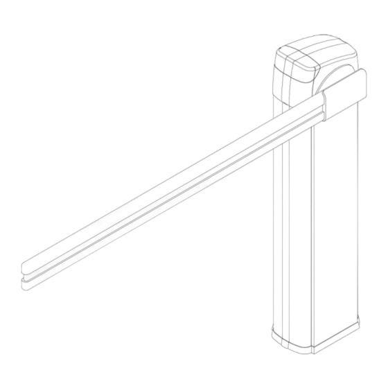
- Page 1 BARRY BARRIER GATE AUTOMATION Installation Manual...
-
Page 2: Technical Specifications
Do not carry out any alteration on the components of the automatic road barrier. Proteco S.r.l. declines all liability in case not original components or additional devices are used. Automatic road barriers are not for pedestrians! BARRY road barriers are designed for vehicular traffic only. -
Page 3: Installation
3. INSTALLATION 3.1 Fixing to the ground Fig.1 3.2 Assembling the boom Fig.2 Fig.3 Adjusting nut Spring 3.2 Limit-switch adjusting The magnetic limit-switch and the mechanical limit-switch of the barrier are already pre-set for an optimal movement of the boom. Limit-switches position doesn’t need to be changed. Fig.4... -
Page 4: Adjusting The Boom
4. ADJUSTING THE BOOM 4.1 Short boom In case you need to use a shorter size of the telescopic boom, please pay attention to the following adjustments The boom could slightly raise once shorted. In this case, you might need to reduce the springs quantity (please see appendix). - Page 5 4.2 Long boom In case you need to use the longest size of the telescopic boom, please pay attention to the following adjustments The boom could slightly slope downward once longer. In this case, you might need to increase the springs quantity (please see appendix).
- Page 6 5. RELEASE FOR MANUAL OPERATION Please see picture below Fig.5 When unlocking the boom could suddenly move upwards. Always control the boom movement with your hands. 6. ELECTRICAL SET-UP Motor, control panel and limit-switches are already wired. Optional controls or safety devices, such as photocells, loop detectors or air-wave switches can be connected to the automatic road barrier.
- Page 7 7A. WIRING AND PROGRAMMING SET-UP (AC version) 7A.1 Technical specifications Power supply AC 230V 50Hz/ 110V 60HZ Max. consumption Accessories power supply DC12V 8W MAX Working temperature - 20°C ~ +50°C Radio transmitters frequency 433,92 Mhz Automatic closing pause 1 -120” 7A.2 Wiring Scheme (AC version)
- Page 8 1 – T1: Transformer 6 – S1: DIP switch block 2 – F1: 0.2A fuse 7 – Reverse function jumper (ON= function 3 – F2: 5A fuse enabled) 4 – VR1: Working force potentiometer 8 – Plug for receiver module 5 –...
- Page 9 7A.5 Opening Safety Devices 7A.5.1 PHOTOCELLS (NC contact) If the infrared beam is obstructed when closing, the barrier immediately reverses If the infrared beam is obstructed when opening, the barrier keeps opening. Receiver (NC) Transmitter 7A.5.2 LOOP DETECTOR (NC contact) If a car enters in the loop’s range when closing, the barrier immediately reverses If a car enters in the loop’s range when opening, the barrier keeps opening.
- Page 10 7A.5.3 LOOP DETECTOR (NO contact) (DIP-switch 2 must be in OFF position) If a car stops in the loop’s range, the barrier stays open Once the car leaves the loop’s range when opening, the barrier closes. 7A.6 External Terminal When an IC card reader is used, it has to be wired to OPN and GND terminals.
- Page 11 7B. WIRING AND PROGRAMMING SET-UP (DC version) 7B.1 Technical specific Power supply AC 230V 50Hz/ 110V 60HZ Max. 120W Accessories power supply DC24V 10W MAX Working temperature - 20°C ~ +50°C Radio frequency 433,92 Mhz Automatic closing pause 1 -120” 7B.2 Wiring Scheme (DC version)
- Page 12 1 – F1: 8A fuse 2 – VR1: Pause time for automatic closing potentiometer 3 – VR2: Opening force potentiometer 4 – VR3: Closing force potentiometer 5 – DIP-switch block 6 – Power switch for lights 7 – Plug for receiver module 8 –...
- Page 13 7B.5 Opening Safety Devices 7B.5.1 PHOTOCELLS (NC contact) If the infrared beam is obstructed when closing, the barrier immediately reverses If the infrared beam is obstructed when opening, the barrier keeps opening. Transmitter Receiver (NC) 7B.5.2 LOOP DETECTOR (NC contact) If a car enters in the loop’s range when closing, the barrier immediately reverses If a car enters in the loop’s range when opening, the barrier keeps opening Note: If the automatic closing function is on, the barrier automatically closes after a pause time.
- Page 14 7B.5.3 LOOP DETECTOR (NO contact) (DIP-switch 1 must be in OFF position) If a car stops in the loop’s range, the barrier stays open Once the car leaves the loop’s range when opening, the barrier closes 7B.6 External Terminal When an IC card reader is used, it has to be wired to OPN and GND terminals.
-
Page 15: Radio Programming
8. RADIO PROGRAMMING 8.1 How to program a radio-transmitter 1. Press the button on the receiver card, when the LED lights on release it 2. Press the radio-transmitter’s button you want to use till the light gets off 3. The radio-transmitter is now coded into the receiver. Additional radio-transmitters can be coded following the same procedure 8.2 How to delete a radio-transmitter Press the button on the receiver card till the LED lights on and hold it pressed till the light gets off.
Need help?
Do you have a question about the BARRY and is the answer not in the manual?
Questions and answers